
Related Manuals for GARO GLB****-B series


Summary of Contents for GARO GLB****-B series
- Page 1 GARO Charger GLB ..-B Basic - No Load Balancing Model End User Instruction (EN) K-B-18-03...
-
Page 2: Table Of Contents
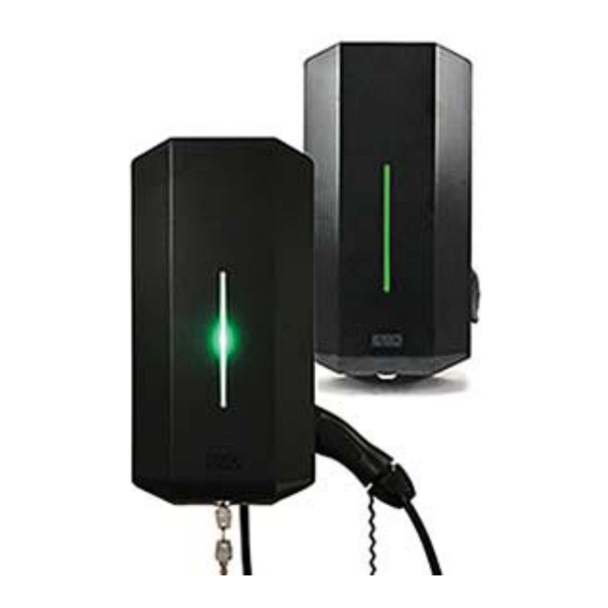
GHL Variants Assembly Instruction for Fitters Mainboard Simplified Connection Diagram Step-by-Step Installation Setting The Charging Current Troubleshooting Technical Data Drill template GHL Wallbox (see the back of the box) GARO Wallbox 380175-3 Assembly instructions/User Instructions (EN) Keys Manual Language labels... - Page 3 GARO Wallbox Charger GLB with GARO Wallbox Charger GLB cable and connector, type 1 or 2 with type 2 socket outlet (figure 1) Front cover Cover (figure 3) Base box Indication light Connector type 1 or 2 Type 2 socket Personal protective circuit breaker, residual‐current circuit breaker and energy (figure 2) meter, if required.
-
Page 4: Assembly Instruction For Fitters
Assembly instructions for fitters SW1 OCPP/Wi‐Fi not Protective earth (PE) available in GHL GKN11 1 2 3 4 5 6 Congratulations on selecting a GARO Wallbox EV Charger and contributing to a better A ‐ E‐Meter GK32 environment. The GARO Charger is an A C charger enabling Mode 3 charging which Ext. charge control Remote control open=on, close=off complies fully with the requirements of IEC 61851‐1 and IEC TS 61439‐7. *) ‐ see infobelow A‐ DataLink B + The product complies with IP Code IP44, with a closed front. It is to be fitted to a wall, and all installation must be carried out by an authorised fitter and Max charging Factory default ... -
Page 5: Step-By-Step Installation
Step-by-Step installation Ensure the supply cable is not live. Remove the drill template from the packaging. Attach the drill template to the wall where the charger will be installed. Suitable height (see Technical data on page 45) Drill/mark in accordance with the instructions on the drill template. (figure 5) (figure 6) Unlock the front cover with the key provided and slide the cover downwards. Loosen the seven screws and carefully remove the cover from the base box. The front cover has a built‐in stop‐position. To move past this position, grip the underside of the cover and lift outwards gradually while pulling downwards. - Page 6 (figure 9) (figure 10) Re‐install the front cover by feeding it in from below. Connect the power and ensure the indication light is constantly green. Lock the front cover with thekey. If, not refer to the section on: Troubleshooting. When the green light shines constantly, the charger is ready for use.
-
Page 7: Setting The Charging Current
Setting The Charging Current Setting the charging current – Switch 2 Setting the amperage for main fuses Depending on the size of the fuse, overload may occur, primarily at the property's meter During installation, the amperage of the DIP switch SW1(1‐2‐3) must be adjusted to fuse. The wallbox's charging current can be reduced using the switches on the circuit correspond with the size and strength of the main fuses. board. The supply voltage must be broken before the charging current is reduced. The DIP switch SW2(1‐2‐3‐) which controls the charger's maximum permitted charging current should be set to the recommended current values outlined below. Main fuse SW1(1‐2‐3) 63A SW2(1‐2‐3) S W 2 S W 2 SW2‐4 On = Fixed cable Off = Type 2 outlet with locking actuator Always ensure SW 4 is in ON position (figure 11) -
Page 8: Troubleshooting
IEC 61851‐1 and IEC TS 61439‐7 Constant red light personal protective current Resetting the residual‐current breaker or personal protective current has been tripped. breaker. Installation: on wall or Garo Wallbox stand Constant yellow light Broken cable Check cable Voltage rating: 2 3 0 V / 4 0 0 50Hz Flashing yellow light Motor lock socketnot in Contact a qualified latched position.
Need help?
Do you have a question about the GLB****-B series and is the answer not in the manual?
Questions and answers