Table of Contents
Advertisement
Quick Links
Advertisement
Table of Contents

Related Manuals for GARO Wallbox GLB+


Summary of Contents for GARO Wallbox GLB+
- Page 1 GARO Wallbox GLB+ 380200-2.0 Assembly instructions / End User Instruction (EN)
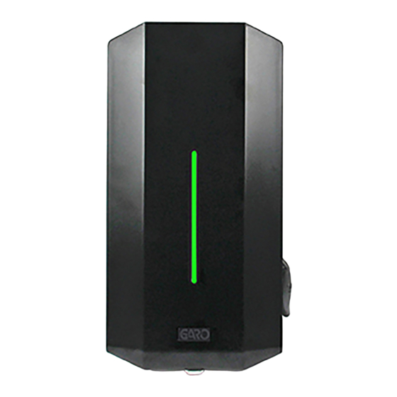
- Page 2 GARO Wallbox GLB+ GARO Wallbox GLB+ with cable and connector, type 1 or 2 with type 2 socket outlet (figure 1) Front cover Cover (figure 3) Back panel Indication light Connector type 1 or 2 Type 2 socket outlet RCCB (Residual Current Circuit Breaker) or RCBO (Residual Current Breaker with (figure 2) Overcurrent Protection).
-
Page 3: Table Of Contents
Dimensional drawing This document contains general descriptions which are verified to be accurate at the time of printing. However, because continuous improvement is a goal at GARO, we reserve the right to make product modifications at any time. Assembly instructions for installer... -
Page 4: Safety Information
Safety Information Safety Information Safety Information Hazard categories and special symbols The GLB+ Wallbox must be grounded through a permanent wiring system. Read these instructions carefully before trying to install, operate, or maintain the wallbox. Save the manual for future use. Do not install or use the GLB+ Wallbox near flammable, explosive, harsh, or combustible materials, chemicals, or vapors. - Page 5 Safety Information Safety Information Cautions Do not use private power generators as a power source for charging. The front cover must always be locked in its upper position in order to ensure compliance with IP Code IP44. Incorrect installation and testing of the GLB+ Wallbox could potentially damage Avoid mounting the wall box in direct sunlight.
-
Page 6: Technical Data
Technical data Technical data Specifications Product type: all GLB models Standards/directives: IEC 61851-1 and IEC TS 61439-7 Installation: on wall Voltage rating: 230V/400 50Hz Installation systems: TT, TN and IT systems Charging type: Mode 3 IP classification: IP44 Mechanical impact IK08 resistance: Application temperature:... -
Page 7: Dimensional Drawing
Dimensional drawing Dimensional drawing (figure 5) -
Page 8: Assembly Instructions For Installer
The product complies with IP Code IP44, with a closed front. It is designed to be fixed to a wall or mounted on a GARO Wallbox stand and all installation must be carried out by a qualified installer and comply with local installation regulations. -
Page 9: Box Contents
Assembly instructions for installer / Box Contents Assembly instructions for installer / Tools and material required Box Contents Tools and Materials Required Before installing the Garo Wallbox, gather the folllowing tools and materials: • Pencil or marker • Hole punch (optional, to push through cardboard template) •... -
Page 10: Step-By-Step Installation
Assembly instructions for installer / Step-by-Step installation Assembly instructions for installer / Step-by-Step installation Step-by-Step Installation (figure 7) Read Safety Instructions All installation must be carried out by a qualified installer and comply with local installation regulations. (figure 8) Ensure the supply cable is isolated Turn off input power at the circuit breaker before installing, configuring Drill/mark in accordance with the instructions on the drill template. - Page 11 Assembly instructions for installer / Step-by-Step installation Assembly instructions for installer / Step-by-Step installation Connection of phases for 3-phase Screw the back panel onto the wall using three screws suitable for the wall charger to 3-phase system as below. When connecting a 3-phase charger to surface.
- Page 12 Assembly instructions for installer / Step-by-Step installation Assembly instructions for installer / Step-by-Step installation 7 x T20 label explaining charger status indication language label is placed on the side English information label (figure 11) (figure 10) Carefully place the cover in position from the front. Ensure the inserts on the right hand side fit into the groove and the cover is perfectly positioned all around.
- Page 13 Assembly instructions for installer / Step-by-Step installation (figure 12) Connect the power and ensure the indication light is solid green. If, not refer to the section on: Troubleshooting When solid green light is shown, the charger is ready for use. To confirm that the GLB+ Wallbox is functioning correctly after installation, test with an EVSE test box.
-
Page 14: End User Instruction
The product complies with IP Code IP44, with a closed front. charging electric vehicles. It is to be fitted to a wall or GARO Wallbox stand, and all installation must be carried out by a qualified installer and comply with local installation regulations. -
Page 15: Charging Electric Vehicles
End user instrucion End user instrucion / Charging electric vehicles Charging electric vehicles Connect the wallbox to the vehicle using the cable. When charging starts, a pulsing blue light intensity indicates charging in progress. Stop charging. As a rule, the wallbox socket and vehicle inlet locks the cable. As a result, charging must be stopped from the vehicle before the cable is removed. -
Page 16: Resetting/Conditioning Of Rccb Or Rcbo
End user instrucion / Resetting/Conditioning of RCCB or RCBO End user instrucion / Resetting/Conditioning of RCCB or RCBO Resetting/Conditioning of RCCB or RCBO Do not modify the equipment installation or any part of the product. Do not touch the GLB+ Wallbox’s end terminals with fingers or any other objects. Do not insert foreign objects into any part of the GLB+ Wallbox. -
Page 17: Care
End user instruction/ Care End user instruction / Troubleshooting Care Troubleshooting Do not install or use the GLB+ Wallbox near flammable, explosive, harsh, or Indication Type of fault Measure combustible materials, chemicals, or vapors. Constant red light The residual-current or Reset. -
Page 18: Index
Index INDEX Symbols Front cover 2 Voltage rating 11 Application temperature 11 Assembly instructions 14 Warnings 6 Weight 11 Back panel 2 RCBO 2 Box Contents 16 Important information for installer 14 RCCB 2 Indication light 2 Resetting/Conditioning of RCCB or RCBO 31 Installation height 11 Cable length 11 IP classification 11... - Page 19 GARO AB Box 203, SE–335 25 Gnosjö Phone: +46 (0) 370 33 28 00 Fax: +46 (0) 370 33 28 50 info@garo.se garo.se...
Need help?
Do you have a question about the Wallbox GLB+ and is the answer not in the manual?
Questions and answers