
Related Manuals for Extron electronics PoleVault Systems PVS 300


Summary of Contents for Extron electronics PoleVault Systems PVS 300
- Page 1 PoleVault Systems Installation Guide for the PVS 200, 300, and 400 68-1390-01 Rev. C 10 08...
- Page 2 Precautions Safety Instructions • English This symbol is intended to alert the user of important operating and maintenance (servicing) instructions in the literature provided with the equipment. This symbol is intended to alert the user of the presence of uninsulated dangerous voltage within the product’s enclosure that may present a risk of electric shock.
- Page 3 Introduction FCC Class A Notice This equipment has been tested and found to comply with the limits for a Class A digital device, pursuant to part 15 of the FCC Rules. Operation is subject to the following two conditions: (1) this device may not cause harmful interference, and (2) this device must accept any interference received, including interference that may cause undesired operation.
- Page 4 Introduction, cont'd Audio Video In D IO (x2) PVT RGB D 1 Gang RGB and Audio Input Video In PVS 204SA D IO PoleVault Switcher V ID PVT CV D 1 Gang Video and Audio Input Video In D IO (x2) PVT RGB D 1 Gang...
- Page 5 Before you Begin Installation - Planning Before installation is started, several major factors must be considered to ensure that the overall installation is as smooth and trouble free as possible, and that the final finished project meets the needs of the customers, users, audiences, and installer.
- Page 6 Introduction — Planning, cont’d • Lighting Type and control (important for projector image viewing) Ambient light from windows Windows TV / VCR / DVD Inputs PVT A/V Wallplate Location Example classroom installation b. Location of the screen and projector •...
- Page 7 • Viewing obstructions Pillars, furniture etc., window locations for glare reduction, obstructions between projector and screen c. Location of MediaLink Controller and Wall Plates • Forward and side reach (for full details refer to a copy of "ADA Standards for Accessible Design", "Section 4-2", "Space Allowance and Reach Ranges") 48"...
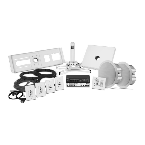
- Page 8 Introduction — Inventory Overview Inventory a. Included items The PoleVault System (PVS xxx) ships in two boxes. The larger box (42-1xx-xx) contain the devices and hardware, individually boxed and labeled. Each PVS system has the same quantities of speakers, hardware and devices, but differ in the number and type of PoleVault A/V Source Input Wall Plates, and are shipped as follows: •...
- Page 9 PoleVault System Devices and Hardware, (cont'd) PoleVault System Devices and Hardware, cont’d PVT CV D PVT RGB D White PVT CV D White 60-819-13 PVT CV D Wallplate (1) Mud ring (1) Mud ring (2) Dog legs (2) Dog legs (2) Dog leg screws (2) Dog leg screws (2) PVT mounting screws...
- Page 10 — Introduction Inventory Overview, cont’d (2) Speaker grills (8 pcs) Grill putty (1) Grill key If any items in the PoleVault System boxes are damaged or missing, contact the Extron Technical Hotline (see rear cover for contact numbers). PoleVault Systems Installation • Introduction — Inventory Overview PoleVault System Ceiling Speakers PV SI 3C LP White 42-103-13...
- Page 11 b. Items not included The following items are not included. However, input and display devices are essential parts of the system, and at any installation they may vary depending on their use. This list suggests various devices that may be used. •...
- Page 12 — Introduction Inventory Overview, cont’d d. Installation tools To aid the professional installer, this checklist gives the tools recommended to complete the installation. Tools should include, but are not confined to: • Laser level, or two levels (large for screen installation, small for wall plates and projector mounts) •...
- Page 13 Installation Overview Installation Overview This overview outlines the basic steps for installing the PoleVault System. Detailed description of these steps is given in five sections, Stages One though Five. N Additional installation hardware is needed and should be supplied by the installer. See Introduction, “Items not included”, for a list.
- Page 14 Stage One — Install the Screen and Projector Stage 1 This stage involves installing the three pieces of hardware shown below. PCM 240 Projector Ceiling Mount 1-gang and 2-gang Accessory Mounting Points (e.g. power sockets) Pipe Pipe Adapter Adapter Set Screws (2) T-bar Securing Screws (4)
-
Page 15: Mark Screen Location
1. Mark screen location a. Mark the center line and the outer edges of screen. T When marking the location of screens, devices, or site for installing transmitters and MediaLink control devices, use painters’ tape to avoid wall surface damage. When marking the center line of the screen, where possible, keep it aligned with the center of the ceiling tile. -
Page 16: Verify The Image Location
Installation — Stage One, cont’d e. Using suitable screws, mount the projector onto the lower portion of the UPB 25 (the projector bracket, see b in step 2d’s drawing). Align it so the security flange is at the rear. A minimum of three arms need to be attached to the projector Adjust the arms to fit as needed. -
Page 17: Cut The Ceiling Tile
4. Cut the ceiling tile a. Mark the location of the PCM 240 on the T-bar, before removing it. This aids putting it back in the correct location when the tile is replaced. T Mark the screen direction on back of the tile (e.g. with an arrow or “to front”) to help orientation of tile when replacing it after cutting. - Page 18 Installation — Stage One, cont’d 6. Secure the Projector Ceiling Mount to the ceiling a. Attach the four turnbuckles to the mounting plate, one at each corner. C DO NOT rest or lean on the mounting plate or suspended ceiling when attaching turnbuckles, tie wire, or when drilling into the ceiling N For safest installation, insert the turnbuckle from the outside so that it hooks inwards.
- Page 19 h. Pass the safety cable through the anchor and attach it to the center holes on either side of the plate. Ensure the cable is of equal length on both sides of the anchor and secure the cable using the cable clamps. T Install any optional power outlets in the 2 gang opening on the mounting plate, towards the outside edge of the mount, so it does not interfere with the PMK 450 when...
- Page 20 Stage Two — Install the Wall Plates and MLC 104 IP Stage 2 This stage involves installing the devices shown below. PVT CV D and PVT RGB D PoleVault A/V Source Input Wall Plates Decora Faceplate AUDIO IN Audio and Video input VIDEO IN connectors...
- Page 21 PVT transmitter installation • CAT 5 T568A signal transmission cables (connects PVT’s to PVS 204SA switcher) MLC 104 IP Plus installation • MLC power and RS-232 control cable (connects the MLC to the MLC/Power control port on the PVS 204SA switcher) •...
- Page 22 Stage Two — Install the Wallplates and MLC 104 IP Plus N The installation must conform to national and local electrical codes, and UL requirements. Refer to the devices’ user manuals for details. 1. Install mud rings N These devices can be installed using the supplied mud ring or a wall box.
- Page 23 2. Pull cables The following cables need to be installed: • CAT 5 cables for signal transmission from the A/V Wall plates to the PVS 204SA. N For PVT RGB D Wall plates, two CAT 5 signal cables for each input are needed. Maximum distance from the PVS 204SA to the Wall plates is 100 feet.
- Page 24 Installation — Stage Two, cont’d 3. Install wall plates a. Connect the CAT 5 cables to the rear of the input devices (for RGB devices, cable labeled A to port A, cable B to port B). b. Mount each device into the mud ring. c.
- Page 25 4. Install MediaLink Controller T Before cabling and installing the MLC 104 IP Plus, locate and write down the MAC address of the device for configuring the IP address. The 12 character alphanumeric address (e.g., 00-05-A6-03-9G-H4) can be found on a label on the rear of the controller. T The length of exposed wire is critical to avoid transmission problems.
- Page 26 Installation — Stage Two, cont’d b. Connect the IR/RS-232 projector communication cable as shown for either RS-232 or IR projector control. c. Connect a CAT 5, 5e, or 6 straight through cable to the MLC ‘s RJ-45 jack. W DO NOT connect the MLC’s RJ-45 jack to the PVS 204SA twisted pair inputs.
- Page 27 The connections between the MLC 104 IP Plus and the PVS 204SA switcher should look like this. e. Sliding the cables into the opening, secure the MLC 104 IP Plus to the mud ring with the provided machine screws POWER 3A MAX PVS 204SA Switcher Rear Panel TCP/IP...
- Page 28 Stage Three — Install the PV SI 3C LP Ceiling Speakers Stage 3 This stage involves installing the devices shown below. Plenum Cover Doglegs (4) Where it goes: Installs in ceiling tiles at predetermined location for best acoustics. Connects to switcher. What it does: Receives and outputs audio signal from PVS 204SA switcher Speaker Installation:...
-
Page 29: Cut Ceiling Tile
N The installation must conform to national and local electrical codes, and UL requirements. Refer to the device’s user manual for details. 1. Cut ceiling tile If installing PV SI 3C LP speakers, do the following: a. Remove the ceiling tiles where the speakers are to be installed. - Page 30 Installation — Stage Three, cont’d e. Loosen the four screws on the front baffle (counter clockwise) 1/2 turn (see figure, A) and turn the doglegs to lock onto the C-ring. Tighten down the front screws (see figure, B). T Use a handheld screwdriver, as a powered screwdriver may slip and damage the speaker.
- Page 31 c. To terminate the cable, strip the end of the cable 0.2" (5 mm) and secure the wires into the supplied 4-pole captive screw connector. d. Plug the 4-pole connector into the speaker terminal and replace and secure the plenum cover N The correct speaker impedance loading must be observed when setting up a speaker system See figures below for examples.
- Page 32 Installation — Stage Three, cont’d 5. Finish speaker installation a. Install/replace the speaker grill on the front of the speaker, using the supplied adhesive tabs (putty) to secure it in place. b. Repeat cabling and final installation steps for all speakers, connecting the speakers according to the system preferred (e.g in parallel, see page 2-19) 2-20...
- Page 33 Stage Four — Install the PMK 450 and the PVS 204SA Stage 4 This stage covers installing the devices shown below. Security Screws (2) Bottom Plate (1) Where it goes: Attaches to PMP around cable access hole, above the projector. What it does: Supports and hides the installed PVS 204SA switcher, power supply, and any installed optional accessories.
- Page 34 Installation — Stage Four, cont’d N The installation must conform to national and local electrical codes, and UL requirements. Refer to the device’s user manual for details. 1. Pull the cables a. Loosen the PCM 240 set screws and remove the PMP. b.
- Page 35 DO NOT GROUND ® APPARATUS OR SHORT Plenum Rated UL 2043 SPEAKER OUTPUTS Suitable for Use in Air-Handling Spaces RS-232 MLC/IR STEREO AUX/MIX IN Rx IR DC VOL HIGH PASS FILTER A B C DUAL VOL/MUTE MONO Dual DIP Switch Ohms 2-23...
- Page 36 Installation — Stage Four, cont’d 4. Finish installing the Pole Mount kit a. Lift the bottom plate (complete with the PVS 204SA and power supply installed) up to base of the pole and connect the cables as follows: CAT 5 cables according to the cable labels Control/power cable from the MLC 104 IP Plus Speaker cables VGA and...
- Page 37 b. Align the bottom plate lugs with the slots in the top plate and slide up and into place. c. Attach the rear plate to secure the PMK 450. Ensure the power cable exits via the cable notch in the top plate, or via the gap in front of the filler plate at the bottom.
- Page 38 Stage Five — Configure the System Stage Five — Configure the System Stage 5 Items needed to help complete this stage: • Laptop (or PC) with a network connection • GC 2 configuration program (download from www.extron.com) • MLC 104 IP Plus User’s Manual •...
- Page 39 d. Select the MLC 104 IP Plus/PoleVault system from the drop-down box. Follow the instructions on the help page. e. To move to the next page (shown in the yellow box), click the NEXT button above the drop-down box. Repeat as needed, following the instructions on the pages to configure the MLC 104 IP Plus, as needed.
-
Page 40: Test The System
Installation — Stage Five, cont’d 2. Test the system a. Ensure power is supplied to the PVS 204SA switcher, and power on the MLC 104 IP Plus. b. Connect all the input devices (e.g., PC, DVD, document camera, etc.) to the transmitters and power up the input devices. -
Page 41: Final Installation
d. Test the controller’s configuration with the following: • Check that the MLC is controlling the PVS 204SA switcher and projector, and does output the correct image when switching inputs. • Check the projector’s power control (turn it off and on at the MLC controller). •... - Page 42 Optional Accessory Installation — PPC 25 The example below is the installation of the optional accessory Priority Page Controller and Sensor (PPC 25). The Priority Page Controller momentarily silences classroom audio whenever a page is made from a public address (PA) system.
-
Page 43: Specifications
Installation — Reference Information Specifications For detailed specifications and warranty information of the PoleVault System components, refer to the device manuals, or the product pages at www.extron.com. Mounting hardware PCM 240 Mounting ... Drop ceiling mount Enclosure type ... 14 gauge steel/powder coated white Plate dimensions ... - Page 44 Installation — Reference Information, cont’d Devices PVS 204SA External power supply ... 100 VAC to 240 VAC, 50/60 Hz, external, autoswitchable; to 12 VDC, 3 A, regulated Power input requirements ... 12 VDC, 0.97 A (typical) Temperature/humidity ... Storage: -40 to +158 °F (-40 to +70 °C) / 10% to 90%, noncondensing Operating: +32 to +122 °F (0 to +50 °C) / 10% to 90%, noncondensing Enclosure type ...
- Page 45 Extron PMK 450 Low Pro le Multi-Product Pole Mount Kit weight 2.5 lbs (1.2 kg) Extron PMP 6 6” Projector Mount Pole weight 1.0 lbs (0.5 kg) Extron UPB 25 Universal Projector Mounting Bracket weight 3.7 lbs (1.7 kg) Ceiling mount installation diagram (with item weights) for PoleVault System PoleVault Systems Installation •...
- Page 46 Outline of installation steps Stage One — Install the Screen and Projector. c Mark the screen location (page 2-3). c Install projector to verify location (page 2-3). c Verify the image location (page 2-4). c Cut the ceiling tile (page 2-5). c Finish projector ceiling mount installation (page 2-5).
Need help?
Do you have a question about the PoleVault Systems PVS 300 and is the answer not in the manual?
Questions and answers