Advertisement
SMK 1 • Installation Guide
Overview
ATTENTION:
All structural steps and electrical installation must be performed by qualified personnel in accordance with local and
•
national building codes and electrical codes.
Toute étape structurelle et installation électrique, doit être effectuée par un personnel qualifié, conformément aux codes du
•
bâtiment, aux codes incendie et sécurité, et aux codes électriques, locaux et nationaux.
This guide provides instructions for professional installers to mount and install the TLP Pro 525M to a wall or glass surface using
the SMK 1 mounting kit. The kit consists of:
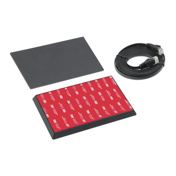
(1) SMK 1 plastic enclosure with an adhesive patch on the back (see figure 1)
•
(4) M3 screws, 6 mm
•
(1) Cover overlay
•
(1) Flat Ethernet cable (10 feet [3 meters]) with RJ-45 connectors
•
SMK 1 Features
A
(4) Cable knockouts (see figure 1)
B
(4) Dimples for wall or furniture mounting holes
C
(4) Mounting points for the TLP Pro 525M mounting plate
Before Starting
Remove one or more knockouts (see figure 1,
enclosure to run cables to the back of the TLP Pro 725M.
You may need to use a sharp knife to cut the plastic holding the
knockout in place.
Attach the SMK 1 to a Flat Surface
Option 1: Mounting the SMK 1 to a Wall with Fasteners
To mount the SMK 1 to a wall or furniture:
Drill holes through the four dimples in the plastic (see figure 1,
1.
and into the mounting surface.
Attach the SMK 1 to the mounting surface, using screws (not
2.
provided) that are appropriate for the mounting surface.
Do not overtighten the screws or the SMK 1 may be damaged.
Option 2: Mounting the SMK 1 to a Glass Surface
Clean both sides of the glass with a lint-free cloth and a 1:1
1.
mixture of isopropyl alcohol and water.
On the outside glass surface, use a strip of painter's tape to
2.
mark the position of the SMK 1 bottom edge (see figure 2,
Use a level (
2
) to ensure it is at the correct angle.
Remove the plastic backing from the adhesive patch on the back
3.
of the SMK 1.
TIP: Wet your fingers to prevent them from sticking to the
adhesive patch.
A
) from the SMK 1
B
)
1
).
A A A
B B B
C C C
e
e
e
A A A
A A A
C C C
B B B
SMK 1 Knockouts and Mounting Holes
Figure 1.
2 2 2
1 1 1
Inside Glass
Surface
Outside Glass Surface
Outside Glass Surface
Preparing the Glass Surface
Figure 2.
B B B
C C C
A A A
C C C
B B B
1
Advertisement
Table of Contents

Related Manuals for Extron electronics SMK 1


Summary of Contents for Extron electronics SMK 1
- Page 1 This guide provides instructions for professional installers to mount and install the TLP Pro 525M to a wall or glass surface using the SMK 1 mounting kit. The kit consists of: (1) SMK 1 plastic enclosure with an adhesive patch on the back (see figure 1) •...
- Page 2 SMK 1 • Installation Guide (Continued) Hold the SMK 1 at a slight angle with the top tilting forward and carefully align the bottom inner edge of the SMK 1 with the painter’s tape (see figure 3, Press the SMK 1 firmly against the glass surface.
Need help?
Do you have a question about the SMK 1 and is the answer not in the manual?
Questions and answers