Advertisement
Setup Guide — TP Transmitters
This guide provides quick start instructions for
an experienced installer to set up and operate
the TP Transmitter Series products. Refer to
www.extron.com for the complete user's manual.
Pre-installation — Jumper settings
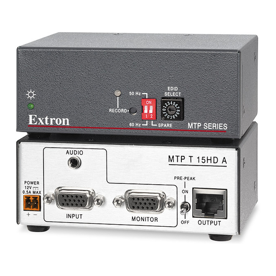
The TP T 15HD A, TP T 15HD AV, and the TP T BNC DA4 are factory
configured to transmit RGB video. You can reconfigure them to transmit
component, S-video, or composite video by using a jumper to connect the
following pins on the main board:
• TP T 15HD A and TP T 15HD AV — Use a jumper to connect pins 1
and 2 at locations J1 and J2 (see the illustration at upper right).
• TP T BNC DA4 — Use a jumper to connect pins 1 and 2 at locations J11
and J12 (see the illustration at lower right).
If using the TP T 15HD AV with a TPX 88X transmitter or with
N
an older, unmodified receiver, refer to the TP Transmitters User's
Manual, "Audio jumpers", for information on audio jumper
placement for compatibility.
Installation
Step 1 — Mount the unit
Turn off or disconnect power to all equipment, and mount the transmitter as desired.
Step 2 — Connect inputs
Attach input cables to the audio and video connectors as applicable for your TP T model.
• Composite video — Connect a composite video source device to the Video RCA jack
(TP T 15 HD AV), the G pin of the Computer Input HD connector (TP T 15HD A), or the
G BNC connector (TP T BNC DA4). For three separate genlocked video signals on the
TP T BNC DA4, connect the input device to the R, G, and B BNC connectors.
• S-video — Connect an S-video source device to pins R (chroma) and G (luma) of the
Computer Input HD connector (TP T 15 HD A and TP T 15 HD AV), or to the R (C-chroma)
and G (Y-luma) BNC connectors (TP T BNC DA4).
• Component video — Connect a source device to pins R (R-Y), G (Y), and B (B-Y) of the
Computer Input HD connector (TP T 15 HD A and TP T 15 HD AV), or to the R (R-Y), G (Y)
and B (B-Y) BNC connectors (TP T BNC DA4).
• RGBHV computer video — Connect an RGB source device to the female Computer Input
HD connector (TP T 15 HD A and TP T 15 HD AV) or to the R, G, B, H/HV, and V female
BNC connectors (TP T BNC DA4).
• RGBS computer video — Connect an RGB source device to the female Computer Input
HD connector (TP T 15 HD A and TP T 15 HD AV) or to the R, G, B, and H/HV female BNC
connectors (TP T BNC DA4).
• Audio input — Connect PC audio to the 3.5 mm stereo jack (TP T 15HD A and
TP T 15HD AV).
• Audio input L and R pair — Connect left and right stereo audio to the RCA connector pair
(TP T 15HD AV only).
N
Input only analog line level audio signals on these connectors.
Component,
S-video,
Composite
RGB
1
1
1
TP T 15HD A
TP T 15HD AV
TP T BNC DA4
Component,
RGB
S-video,
Composite
(Continued on reverse side)
1
1
1
Advertisement
Table of Contents

Related Manuals for Extron electronics TP Series


Summary of Contents for Extron electronics TP Series
- Page 1 Setup Guide — TP Transmitters This guide provides quick start instructions for an experienced installer to set up and operate the TP Transmitter Series products. Refer to www.extron.com for the complete user’s manual. Component, Pre-installation — Jumper settings S-video, Composite The TP T 15HD A, TP T 15HD AV, and the TP T BNC DA4 are factory configured to transmit RGB video.
- Page 2 Inside Asia Only +81.3.3511.7656 FAX Inside China Only +971.4.2991880 FAX Inside USA / Canada Only Rev. A +1.919.863.1794 +31.33.453.4040 +65.6383.4400 +86.21.3760.1568 +1.714.491.1500 +1.919.863.1797 FAX +31.33.453.4050 FAX +65.6383.4664 FAX +86.21.3760.1566 FAX 02 09 +1.714.491.1517 FAX © 2009 Extron Electronics. All rights reserved.
Need help?
Do you have a question about the TP Series and is the answer not in the manual?
Questions and answers