
Related Manuals for Baicells ATOM OD15

Summary of Contents for Baicells ATOM OD15
- Page 1 ATOM OD15 CPE Installation & Configuration Guide Model EG8015G-M11 April 2020 Version 1.2...
- Page 2 Baicells Technologies, Inc., copyrights the information in this document. No part of this document may be reproduced in any form or means without the prior written consent of Baicells Technologies, Inc. The Baicells logo is a proprietary trademark of Baicells Technologies, Inc. Other trademarks mentioned in this document belong to their owners.
-
Page 3: Table Of Contents
Table of Contents Introduction ............................... 5 1.1. Description ..............................5 1.2. ODU Modes ..............................5 1.3. Features................................. 7 Installation ................................. 7 2.1. Part & Materials ............................. 7 2.2. LEDs & Interfaces ............................8 2.3. CPE Software ..............................9 2.4. Login................................9 2.5. - Page 4 2.9.3. ALG ................................29 2.10. System Menu ..............................29 2.10.1. Account ..............................29 2.10.2. WEB Settings ............................30 2.10.3. NTP ................................30 2.10.4. TR-069 ..............................30 2.10.5. TR-069 Certificate .............................31 2.10.6. Restore / Update............................31 2.10.6.1. Firmware Update ..........................31 2.10.6.2. Restore Factory Settings........................32 2.10.7. Diagnosis ..............................32 2.10.7.1. TCPDump .............................32 2.10.7.2.
-
Page 5: Introduction
Introduction 1.1. Description The Baicells Atom OD15 Outdoor Low-Gain and Outdoor High-Gain User Equipment (UE) is part of a broadband wireless access system that integrates with Long-Term Evolution (LTE) backhaul networks to provide subscribers with Internet access. The UE, also referred to as Customer Premise Equipment (CPE), communicates through a wireless connection to the operator’s eNodeB’s (eNB) at cell sites located in the... - Page 6 (2) IDU+ODU Mode When the ODU connect to a IDU device (Baicells PoE router), it will automatic be configured as Bridge mode, and assign all its LTE IP to IDU, at that mode, the IDU will take the place of ODU to control all the CPE functions.
-
Page 7: Features
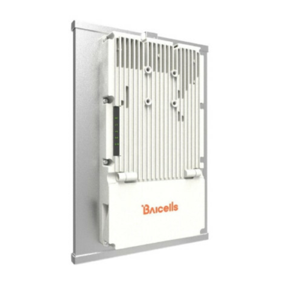
TR-069 management protocol support Local and remote GUI management Installation 2.1. Part & Materials Refer to Table 1 for a list of the components that you should receive with the Baicells outdoor UE. Table 1: Parts Item Picture Atom OD15 unit... -
Page 8: Leds & Interfaces
Atom OD15 Mounting 1 each Bracket You will need standard tools, Ethernet cable, ground wire, and RJ-45 connectors for installing and connecting the outdoor unit (Table 2). Table 2: Materials Item Description Ethernet Cable Outdoor shield CAT5E, shorter than 330 feet... -
Page 9: Cpe Software
Ground lug. The unit is connected to Earth by conductor. 2.3. CPE Software The firmware of the CPE should be BaiCE_BG_1.5.4 or above, if the CPE is not running this version, please download it from the Baicells website > Resources > Firmware or contact Baicells support. - Page 10 The Device Info pane displays the product name, software version, serial number, etc. The LTE Status pane shows important operational information, such as the CPE's SIM card status and its IMSI and IMEI numbers, wireless frequency being used, eNB connection status, and current signal strength and quality. Under Throughput Statistics you will see downlink (DL) and uplink (UL) data rates for current throughput (kbps), average rates, peak rates, and total throughput.
- Page 11 Figure 6: LAN Status Figure 7: Device List Table 3: Status Field Name Description Connection State Connection status between the CPE and the network – either Checking SIM, Scanning, Registering, Acquiring IP, Connected, or Disconnected Signal Intensity Indicates the strength of the signal between this CPE and the serving eNB, either excellent, good, general, bad, or severe.
- Page 12 EARFCN The E-UTRA Absolute Radio Frequency Channel Number (band and frequency) within which the CPE operates Bandwidth The range of frequencies within the band the CPE may use for wireless communications with an eNB, expressed in MHz CINR The Channel Signal-to-Interference-plus-Noise Ratio reflects the signal strength of the signal received from the two antennas in the eNB, expressed in decibels (dB) NOTE: Additional SINR values are reported when a transmitting device is using more than two antennas.
-
Page 13: Network Menu
2.6. Network Menu 2.6.1. LAN Settings Enter the Network > LAN DHCP Server enable, IP address, subnet mask, DHCP range, lease time, UPNP enable. Figure 8: DHCP Settings DHCP Static Leases settings can set by the host’s MAC address. Figure 9: DHCP Static Leases... -
Page 14: Wan Settings
2.6.2. WAN Settings 2.6.2.1. NAT Mode The CPE will be worked at NAT mode, and all 8 APNs can be configured by Default router/Data/Mgmt/Voip bear types. Figure 10: WAN Settings 2.6.2.2. Router Mode When selected Router mode, the CPE will worked at router mode, it can dynamic update router tables. Figure 11: Router Mode 2.6.2.3. -
Page 15: Bridge Mode
Figure 12: Tunnel Mode 2.6.2.4. Bridge Mode When the CPE worked at Bridge mode, the WAN ports address will bridge to LAN port, and the LAN port will worked at trunk mode. Figure 13: Bridge Mode 2.6.2.5. Mixed Mode Mixed mode can configured every APN with different mode (e.g. Bridge), this is a professional mode. -
Page 16: Static Routes
Figure 14: Mixed Mode 2.6.3. Static Routes Set Static routes of the CPE, it can configure LAN or WAN port routes, Gateway, Destination Network and Route Subnet Mask, in Current Settings, show all activated static routes. Figure 15: Static routes... -
Page 17: Dmz
2.6.4. In technology, the DMZ refers to a firewall between incoming WAN traffic and the LAN to which the CPE is connected. Two basic DMZ methods are (a) using a single firewall, also known as the three-legged model, and (b) using dual firewalls (Figure 36). These architectures can be expanded to create complex architectures depending on the network requirements. -
Page 18: Lte Menu
2.7. LTE Menu 2.7.1. Connection Settings LTE connection settings includes Roaming settings, Default connection settings and Power Scan Option. Figure 19: Connection Settings 2.7.1.1. Roaming setting If set Roam enable, the CPE can access to other PLMN network, else the CPE just can access the network PLMN same with the SIM card. -
Page 19: Edit Apn Profile
The CPE supports 8 APN configurations. At least one APN (TR-069) must be configured when the CPE/eNB connect to the Baicells CloudCore. In the window (Figure 42) you will select the APN number (1-8), enable it, enter an APN Name, select the type of IP addressing (IPv4, IPv6, or IPv4v6), identify if it is the default gateway, and choose which type of protocol will be supported on it. -
Page 20: Cell Selection
Figure 23: PIN Management 2.7.4. Cell selection The Cell selection determines which frequencies the CPE’s routine scan of available frequencies will cover. Scanning is a process of tuning to a specific frequency and measuring the simplest signal quality [e.g., Received Signal Strength Indication (RSSI)]. As part of the cell selection and re-selection process, the CPE performs the scan first and then selects a small number of candidate cells to go through the next step of measuring and evaluating signals to select the best eNB that can serve it. - Page 21 Figure 25: Dedicated EARFCN Figure 26: Cell Lock...
-
Page 22: Sim Lock Settings
Figure 27: PCI Only Lock 2.7.5. SIM Lock Settings This feature may be used to lock the SIM card to the operator's network (Figure 48). Each operator has a unique Public Land Mobile Network (PLMN) number. Locking the SIM prohibits the users from accessing another operator's network. -
Page 23: Security Menu
2.8. Security Menu 2.8.1. IP Filtering When using a firewall server in the local network, invoke this setting to enable or disable the firewall for this CPE (Figure 50). Figure 30: Firewall Basic Settings When enable IP/Port Filtering, then the IP/Port Filter can be set. Figure 31: IP / Port Filtering Settings: (1) IP/Port Filtering Mode: Blacklist, White list... -
Page 24: Mac Filtering
Figure 32: IPv6 Filtering Settings: (1) IPv6 Filtering Mode: Blacklist, White list (2) IPv6 Filtering Log Dropped: enable / disable (3) Destination IP Address: the destination IP Address of the filter (4) Source IP Address: the source IP Address of the filter (5) Protocol: TCP, UDP, TCP/UDP, ICMPv6, ALL (6) Destination Port Range: the range of port (7) Source Port Range: the range of port... -
Page 25: Url Filtering
(2) MAC Filtering Log Dropped: enable / disable (3) MAC Address: the filtering MAC address 2.8.4. URL Filtering The Uniform Resource Location Filter (URL Filter) allows you to define a list of URL addresses users are forbidden from accessing. When you enable the filter, a Settings window appears. Enter the specific URL address users cannot access, as shown in Figure 54. -
Page 26: System Security
2.8.5. System Security Figure 35: System Security System Security Profiles, include High, Medium, None and Custom, every profiles will corresponding with a set of System Security Settings. Settings: (1) Remote Web Login: enable / disable (2) Remote Telnet: enable / disable (3) Access Control List: enable / disable (4) Block Port Scan: enable / disable (5) Block Syn Flood: enable / disable... -
Page 27: Schedule
2.8.7. Schedule This feature is set for a group schedule list, like start from 2020.8.18 to 2020.8.20 as a index of the schedule. Figure 37: Schedule List In previous Filter configurations, you can select the schedule index like below figure. Figure 38: Schedule Settings... -
Page 28: Nat Menu
2.9. NAT Menu 2.9.1. Port Forwarding When NAT mode is enabled as the WAN interface type (section 3.5.2), you can redirect a communication request from one address and port number combination to another. Only the IP address on the WAN side is open to the Internet. -
Page 29: Alg
System Menu 2.10.1. Account This menu is used to change the login password for the CPE (Figure 62). The password must be 5 to 12 characters. Baicells recommends using a combination of upper- and lower-case letters and numbers. Figure 42: Account... -
Page 30: Web Settings
2.10.2. WEB Settings WEB Setting provides the ability to configure and manage the CPE remotely (Figure 63). This is especially helpful when a user calls in for technical assistance. In section 3.3 Login, you used this Web application with Refer to 错误!未找到引用源。 for a description of each field. the default URL of http://192.168.150.1. -
Page 31: Tr-069 Certificate
Caution: Do not power off the CPE or disconnect it from the computer during an upgrade. To update (upgrade) the CPE to a different firmware version (Figure 67): 1. Download the image file from the Baicells support website (Baicells > Support > Downloads), and save it to your computer. -
Page 32: Restore Factory Settings
2.10.6.2. Restore Factory Settings To initiate a restore action, click on the PERFORM RESET button. The CPE will automatically reset its configuration to the factory default values. Figure 47: Restore & update 2.10.7. Diagnosis 2.10.7.1. TCPDump Figure 48: TCPDump Settings Settings: (1) PC IP Address (2) PC PORT... -
Page 33: Trace
(1) IPv4/IPv6: Select the protocol (2) IP Address/Domain: IP Address or URL (3) Count: number of ping count (4) Fragment: yes or no (5) Packet size: 56~1400 Bytes (non-fragment) 2.10.7.3. Trace Figure 50: Trace Diagnosis Settings Settings: (1) IPv4/IPv6: Select the protocol (2) IP Address/Domain: IP Address or URL 2.10.7.4. -
Page 34: Backup Settings
2.10.8. Backup Settings This feature is used to backup the user settings, from the Web-GUI, you can Import / Export the settings. Figure 52: Backup Settings 2.10.9. System Log System log is the debug information of the CPE, when select the Setting, it can Export or Clear Logs. Figure 53: System Log Figure 54: System logs 2.10.10. -
Page 35: Sas Settings
Figure 55: System Message Settings Figure 56: System Messages 2.10.11. SAS Settings Figure 57: System Message Settings... -
Page 36: Reboot
This model can support DP and standalone modes, and all SAS parameters can be configured in Web-GUI, Reboot after you finish setting. 2.11. Reboot Use the Reboot menu to perform a reboot of the CPE, as shown in Figure 77. It can take several minutes for the reboot to complete. -
Page 37: Appendix: Regulatory Compliance
Appendix: Regulatory Compliance FCC Compliance This device complies with part 15 of the FCC Rules. Operation is subject to the following two conditions: (1) This device may not cause harmful interference, and (2) this device must accept any interference received, including interference that may cause undesired operation.
Need help?
Do you have a question about the ATOM OD15 and is the answer not in the manual?
Questions and answers