Table of Contents
Advertisement
Quick Links
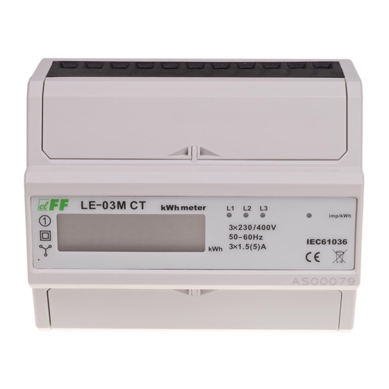
LE-03M CT
Electric energy meter,
3-phase
Do not dispose of this device in the trash along with other waste!
According to the Law on Waste, electro coming from households free of charge and can
give any amount to up to that end point of collec� on, as well as to store the occasion of
the purchase of new equipment (in accordance with the principle of old-for-new, regard-
less of brand). Electro thrown in the trash or abandoned in nature, pose a threat to the
environment and human health.
Purpose
The LE-03M CT is a static (electronic) calibrated electricity meter
of three-phase alternating current in a semi-direct system.
Indicator is designed to work with current transformers for pri-
mary current Ip from 5÷6000 A and secondary current 5 A. The
maximum current measured value of the system is determined
by the primary current Ip applied CT (current transformer).
The user has the ability to set the index value used gear ratio,
which allows you to indicate the actual value taken by the elec-
tricity system.
Serial RS-485 and implemented Modbus RTU communication
protocol allows the indicator used in networks for remote re-
ading of data.
F&F Filipowski sp. j.
Konstantynowska 79/81, 95-200 Pabianice, POLAND
phone/fax (+48 42) 215 23 83 / (+48 42) 227 09 71
www.fif.com.pl; e-mail: biuro@fif.com.pl
- 1 -
Advertisement
Table of Contents

Related Manuals for F&F LE-03M CT


Summary of Contents for F&F LE-03M CT
- Page 1 Electro thrown in the trash or abandoned in nature, pose a threat to the environment and human health. Purpose The LE-03M CT is a static (electronic) calibrated electricity meter of three-phase alternating current in a semi-direct system. Indicator is designed to work with current transformers for pri- mary current Ip from 5÷6000 A and secondary current 5 A.
-
Page 2: Measured Values
Functioning A special electronic system under the influence of current flow and applied voltage in each phase generates pulses in propor- tion to the electricity consumed in this phase. Phase energy consumption is indicated by flashing the corre- sponding LED (L1, L2, L3). The sum of the three phases of pulses indicated by a flashing LED is converted to energy taken in the entire three-phase system, and its value is determined by the segment LCD display. -
Page 3: Pulse Output
Pulse output The meter is equipped with pulse output open collector (OC type). This allows you to connect another pulse device (SO) that reads pulses generated by the meter. No additional connected equipment is required for proper ope- ration of the meter. Constant pulse counter is 12000 pulses/kWh for maximum input current meter, or the secondary current transformer (5 A). - Page 4 Meter number The meter is marked with individual serial number allowing its unambiguous identification. The marking is laser engraved and cannot be removed). Sealing The meter has sealable input and output terminal covers to pre- vent any attempts to bypass the meter. - 4 - - 4 -...
-
Page 5: Wiring Diagram
Wiring diagram - 5 -... -
Page 6: Description Of Terminals
Description of terminals – voltage terminals – pulse output (–) – pulse output (+) – RS-485 output (B) – RS-485 output (A) 15-18 – current terminals Dimensions - 6 -... - Page 7 Mounting 1. Disconnect the power supply. 2. The indicator mounted on a rail in the distribution box. 3. Connect the power in accordance with the markings to the terminals 18 (L1), 17 (L2), 16 (L3). 4. N-wire connect to terminal 15. 5.
- Page 8 Modbus RTU protocol parameters Communication parameters Protocol Modbus RTU Operation mode Slave Baud rate: 9600 bps Port settings Parity: NONE Stop bits: 1 Modbus address 1÷245 (factory settings) Measurement registers com- address description type mand Active energy (R0) Active energy (R1) Active energy (R2) Meter address Legend:...
- Page 9 Register values are stored as integers. To get a reading, the three received registers values should be transform algebraically in accordance with the following formula: (R0 × 256³ + R1 × 256² + R2 × 256 + R3) / x, where: R0 –...
- Page 10 Table of projection numbers and format for Ip currents Ip current Format Ip current value LCD projection number 99999.99 99999.99 99999.99 99999.99 99999.99 99999.99 99999.9 99999.9 99999.9 99999.9 99999.9 99999.9 99999.9 99999.9 99999.9 99999.9 99999.9 - 10 -...
- Page 11 Table of projection numbers and format... cont. Ip current Format Ip current value LCD projection number 99999.9 99999.9 99999 1000 99999 1200 99999 1250 99999 1500 99999 2000 99999 2500 99999 3000 99999 4000 99999 5000 99999 6000 99999 - 11 -...
- Page 12 Technical data installation 4-wire rated voltage 3×230/400 V minimum measured current 0.04 A base current 3×1.5 A maximum current 3×5 A transformer secondary current voltage measuring range 160÷265 V measurement accuracy IEC62052-11, IEC62053-21 rated frequency 50 Hz insulation protection class housing PC+ABS material own power consumption...
-
Page 13: Warranty
working temperature -25÷55°C terminal 25 mm² screw terminals dimensions 7 module (122 mm) mounting on TH-35 rail ingress protection IP20 LE Config service programm Program for test reading of the counted energy value and for basic settings of the meter parameters. Available at www.fif.com.pl (on the device’s subpage). - Page 14 General work safety conditions » Please read the instructions carefully before installation. » The device should be installed and operated by qualified per- sonnel who are familiar with its design, operation, and asso- ciated risks. » Do not install a meter that is damaged or incomplete. »...
Need help?
Do you have a question about the LE-03M CT and is the answer not in the manual?
Questions and answers