Table of Contents
Advertisement
Quick Links
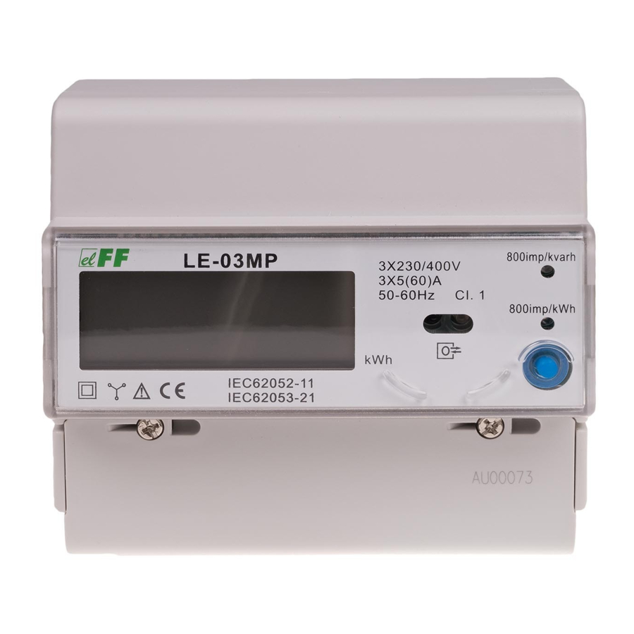
LE-03MP
Electric energy meter,
3-phase
Do not dispose of this device in the trash along with other waste!
According to the Law on Waste, electro coming from households free of charge and can
give any amount to up to that end point of collec� on, as well as to store the occasion of
the purchase of new equipment (in accordance with the principle of old-for-new, regard-
less of brand). Electro thrown in the trash or abandoned in nature, pose a threat to the
environment and human health.
Purpose
The LE-03MP is a static (electronic) calibrated electricity meter
of three-phase alternating current in a direct system. It is used
for reading and recording of consumed electric energy and ma-
ins parameters with remote readout via a wired RS-485 network.
Functioning
Under the influence of flowing current and applied voltage, the
LE meter accurately measures the amount of consumed electrici-
ty. Energy consumption is indicated by flashing LEDs: 800 pulses/
kWh for active power and 800 pulses/kvar for reactive power. In
addition, the device measures the mains parameters. The values
are displayed cyclically on LCD display. Parameter changes every
3 seconds. You can manually switch between successive parame-
ters by pressing a button on the front-end of the meter.
The display is active only with meter power supply on.
F&F Filipowski sp. j.
Konstantynowska 79/81, 95-200 Pabianice, POLAND
phone/fax (+48 42) 215 23 83 / (+48 42) 227 09 71
www.fif.com.pl; e-mail: biuro@fif.com.pl
- 1 -
Advertisement
Table of Contents

Related Manuals for F&F LE-03MP


Summary of Contents for F&F LE-03MP
- Page 1 Electro thrown in the trash or abandoned in nature, pose a threat to the environment and human health. Purpose The LE-03MP is a static (electronic) calibrated electricity meter of three-phase alternating current in a direct system. It is used for reading and recording of consumed electric energy and ma- ins parameters with remote readout via a wired RS-485 network.
- Page 2 The meter has an internal relay that switches L1, L2 and L3 cir- cuits. The (ON/OFF) relay can be also operated manually. The meter has a program overcurrent protection. If the load threshold is exceeded, the internal relay opens for 5 minutes. After that time the relay closes and the measurement is repe- ated.
-
Page 3: Measured Values
Features » Internal relay switching L1, L2, L3 phase circuits. » Remote control of ON/OFF relay. » Overcurrent protection – setting the load threshold. » Prepaid power (prepayment) – active power value at which the meter disconnects the internal relay. »... - Page 4 Meter address Change of meter address is done via the RS-485 port using the Modbus RTU protocol command to set the desired value in the meter register. The default meter address: 1. Meter number The meter is marked with individual serial number allowing its unambiguous identification.
- Page 5 Sealing The meter has sealable input and output terminal covers to pre- vent any attempts to bypass the meter. - 5 -...
- Page 6 Front panel Display description - 6 -...
- Page 7 Measured values display order 1. Total active energy 000000.00 kWh 2. Total reactive energy 000000.00 kvarh 3. L1 phase voltage 000.00 V 4. L2 phase voltage 000.00 V 5. L3 phase voltage 000.00 V 6. L1 phase current 00.00 A 7.
-
Page 8: Wiring Diagram
Wiring diagram power input power output power input power output power input power output neutral wire input neutral wire output RS-485 output (B) RS-485 output (A) - 8 -... - Page 9 pulse output 1 (–) [kWh] pulse output 1 (+) [kWh] pulse output 2 (–) [kvarh] pulse output 2 (+) [kvarh] Modbus RTU protocol parameters Communication parameters Protocol Modbus RTU Operation mode Slave Bits per sec: 9600 Data bits: 8 Port settings Parity: NONE Start bits: 1 Stop bits: 2...
- Page 10 Register parameters address description type Meter address: range 1÷255 L1 voltage [V] (×0.01) L2 voltage [V] (×0.01) L3 voltage [V] (×0.01) L1 current intensity [A] (×0.01) L2 current intensity [A] (×0.01) L3 current intensity [A] (×0.01) L1 active power [kW] (×0.001) L2 active power [kW] (×0.001) L3 active power [kW] (×0.001) L1+L2+L3 active power [kW] (×0.001)
- Page 11 Register parameters cont. address description type Prepaid: value of active power top up [kWh] (×0.01) Consumed active power [kWh] (×0.01) (R20×256²+R21)/100 Consumed reactive power [kvarh] (×0.01) (R22×256²+R23)/100 L1 reactive power [kvar] (×0.001) L2 reactive power [kvar] (×0.001) L3 reactive power [kvar] (×0.001) L1+L2+L3 reactive power[kvar] (×0,001) L1 cosφ...
-
Page 12: Technical Data
Technical data installation 4-wire rated voltage 3×230/400 V measured voltage 100÷289 V AC 173÷500 V AC minimum measured current 0.02 A base current maximum current 60 A voltage measuring range 160÷265 V measurement accuracy (IEC62052) 1st class rated frequency 50 Hz overload 30×Imax/10 ms insulation... - Page 13 pulse outputs type open collector maximum voltage 27 V DC maximum current 27 mA output 1 pulse time 10 ms output 2 pulse time 10 ms working temperature -20÷55°C terminal 16 mm² screw terminals dimensions 7 module (122 mm) mounting on TH-35 rail ingress protection IP20...
-
Page 14: Warranty
Warranty F&F products are covered by a 24-month warranty from the date of purchase. The warranty is only valid with proof of purchase. Contact your dealer or contact us directly. CE declaration F&F Filipowski sp. j. declares that the device is in conformity with the essential requirements of The Low Voltage Directive (LVD) 2014/35/EU and the Electromagnetic Compatibility (EMC) Directive 2014/30/UE. - Page 15 General work safety conditions » Please read the instructions carefully before installation. » The device should be installed and operated by qualified per- sonnel who are familiar with its design, operation, and asso- ciated risks. » Do not install a meter that is damaged or incomplete. »...
Need help?
Do you have a question about the LE-03MP and is the answer not in the manual?
Questions and answers