Advertisement
Quick Links
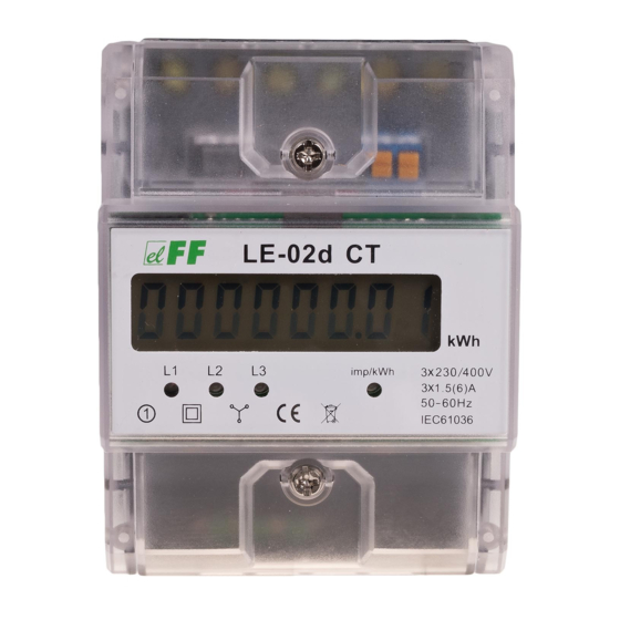
LE-02d CT
Electric energy meter,
3-phase
Do not dispose of this device in the trash along with other waste!
According to the Law on Waste, electro coming from households free of charge and can
give any amount to up to that end point of collec� on, as well as to store the occasion of
the purchase of new equipment (in accordance with the principle of old-for-new, regard-
less of brand). Electro thrown in the trash or abandoned in nature, pose a threat to the
environment and human health.
Purpose
The LE-02d CT is a static (electronic) calibrated three-phase alter-
nating current electricity meter in a semi-indirect system.
The indicator is designed to work with current transformers with
primary current Ip from 5÷6000 A and secondary current 5 A.
The maximum measured current is determined by the value of
the primary current Ip current transformer used.
You can set the index value of the gear used transformers, al-
lowing you to identify the actual value taken by the electricity
system.
Functioning
A special electronic system under the influence of current flow
and applied voltage in each phase generates pulses in propor-
tion to the electricity consumed in this phase. Phase energy
consumption is indicated by flashing the corresponding LED (L1,
L2, L3). The sum of the three phases of pulses indicated by a fla-
shing LED is converted to energy taken in the entire three-phase
system, and its value is determined by the segment LCD display.
F&F Filipowski sp. j.
Konstantynowska 79/81, 95-200 Pabianice, POLAND
phone/fax (+48 42) 215 23 83 / (+48 42) 227 09 71
www.fif.com.pl; e-mail: biuro@fif.com.pl
- 1 -
Advertisement

Subscribe to Our Youtube Channel
Related Manuals for F&F LE-02d CT


Summary of Contents for F&F LE-02d CT
- Page 1 Electro thrown in the trash or abandoned in nature, pose a threat to the environment and human health. Purpose The LE-02d CT is a static (electronic) calibrated three-phase alter- nating current electricity meter in a semi-indirect system. The indicator is designed to work with current transformers with primary current Ip from 5÷6000 A and secondary current 5 A.
-
Page 2: Measured Value
Stored in the memory index values transformer primary current Ip possible to apply. Choosing the right value compatible with the values of external transformers automatically sets the cor- rect ratio, which is calculated according to the actual value of the collected energy. The LCD displays the actual value of the energy consumed in the format depending on the selected gear. - Page 3 Programming Transmission programmable using the button located under the lower casing meter terminals. For safety reasons, the data logging function can make the gear set only once. CT current values Ip inscribed in memory device: 5, 25, 40, 50, 60, 75, 80, 100, 120, 150, 200, 250, 300, 400, 500, 600, 800, 1000, 1200, 1500, 1600, 2000, 2500, 3000, 4000, 5000, 6000.
- Page 4 Meter number The meter is marked with individual serial number allowing its unambiguous identification. The marking is laser engraved and cannot be removed). - 4 -...
- Page 5 Sealing The meter has sealable input and output terminal covers to pre- vent any attempts to bypass the meter. - 5 -...
-
Page 6: Wiring Diagram
Wiring diagram voltage inputs – L1 phase – L2 phase – L3 phase – neutral N-wire - 6 -... - Page 7 current outputs for transformers – L3 output (–) – L3 output (+) – L2 output (–) – L2 output (+) – L1 output (–) – L1 output (+) – pulse output (+) – pulse output (–) If the secondary circuit of the transformer is opened during operation, there is a risk of high voltage on the secondary winding.
- Page 8 Do not tighten the terminals without an inserted wire. This may damage the clamping mechanism or the plastic cover of the termina. 7. Additional pulse receiver connected to terminals 20(+) – 21(–). The terminals are located under the top shell meter terminals. Additional pulse receiver is not required.
- Page 9 indication range dependent on gear constant dependent on gear current consumption signalling 3× red LED read-out signalling red LED pulse output type open collector maximum voltage 27 V DC maximum current 27 mA pulse time 35 ms working temperature -25÷55°C terminal 16 mm²...
-
Page 10: Warranty
Dimensions Warranty F&F products are covered by a 24-month warranty from the date of purchase. The warranty is only valid with proof of purchase. Contact your dealer or contact us directly. CE declaration F&F Filipowski sp. j. declares that the device is in conformity with the essential requirements of The Low Voltage Directive (LVD) 2014/35/EU and the Electromagnetic Compatibility (EMC) Directive 2014/30/UE. - Page 11 General work safety conditions » Please read the instructions carefully before installation. » The device should be installed and operated by qualified per- sonnel who are familiar with its design, operation, and asso- ciated risks. » Do not install a meter that is damaged or incomplete. »...
Need help?
Do you have a question about the LE-02d CT and is the answer not in the manual?
Questions and answers