
Related Manuals for Allied Telesis AT-MC1004


Summary of Contents for Allied Telesis AT-MC1004
-
Page 1: Installation Guide
AT-MC1004 AT-MC1005/1 AT-MC1005/2 AT-MC1005/3 AT-MC1005/4 Gigabit Ethernet Media Converters Installation Guide PN 613-50163-00 Rev B... - Page 2 Copyright 2002 Allied Telesyn, Inc. 960 Stewart Drive Suite B, Sunnyvale CA USA 94085 All rights reserved. No part of this publication may be reproduced without prior written permission from Allied Telesyn, Inc. Ethernet is a registered trademark of Xerox Corporation. All other product names, company names, logos or other designations mentioned herein are trademarks or registered trademarks of their respective owners.
-
Page 3: Electrical Safety And Emission Compliance Statement
408-730-0950 Declares that the product: Gigabit Ethernet Media Converters Model Numbers: AT-MC1004, AT-MC1005/1, AT-MC1005/2, AT-MC1005/3, AT-MC1005/4 This product complies with FCC Part 15B, Class B Limits: This device complies with part 15 of the FCC Rules. Operation is subject to the following two conditions: (1) This device must not cause harmful interference, and (2) this device must accept any interference received, including interference that may cause undesired operation. - Page 4 RFI Emission EN55022 Class B Warning: In a domestic environment this product may cause radio interference in which case the user may be required to take adequate measures. Immunity EN55024 Electrical Safety TUV-EN60950, UL1950, CSA 950 Laser EN60825 Important: Appendix B contains translated safety statements for installing this equipment.
-
Page 5: Table Of Contents
Table of Contents Electrical Safety and Emission Compliance Statement .......iii Welcome to Allied Telesyn ................vii Where to Find Web-based Guides ..............vii Document Conventions ..................vii Contacting Allied Telesyn Technical Support..........viii Online Support ..................viii Telephone Support ...................viii E-mail Support ..................viii Returning Products ................... - Page 6 Table of Contents Chapter 3 Troubleshooting .................... 15 Appendix A Technical Specifications ................17 Physical ......................17 Temperature ..................... 17 Electrical Rating ....................17 Agency Certifications..................17 Fiber Optic Port Specifications ................ 18 Pinout Assignments..................19 Appendix B Translated Safety Statements ..............21...
-
Page 7: Welcome To Allied Telesyn
Welcome to Allied Telesyn This guide contains instructions on how to install the AT-MC1004 and the AT-MC1005/x Series Gigabit Ethernet Media Converters. Where to Find Web-based Guides The Allied Telesyn web site at www.alliedtelesyn.com provides you with an easy way to access the most recent documentation and technical information for all of our products. -
Page 8: Contacting Allied Telesyn Technical Support
Contacting Allied Telesyn Technical Support You can contact Allied Teleysn technical support online or by telephone or e-mail. Online Support You can request technical support online accessing the Knowledge Base at http://kb.alliedtelesyn.com. You can use the Knowledge Base to submit questions to our technical support staff and review answers to previously asked questions. -
Page 9: Returning Products
AT-MC1004 and AT-MC1005/x Series Installation Guide Returning Products Products for return or repair must first be assigned a Return Materials Authorization (RMA) number. A product sent to Allied Telesyn without a RMA number will be returned to the sender at the sender’s expense. -
Page 10: Tell Us What You Think
Tell Us What You Think If you have any comments or suggestions on how we might improve this or other Allied Telesyn documents, please fill out the General Enquiry Form at online. This form can be accessed by selecting “Contact Us” from www.alliedtelesyn.com. -
Page 11: Chapter 1 Overview
Ethernet data between twisted pair cabling and either multimode or single- mode fiber optic cabling. The AT-MC1004 media converter features a 1000Base-SX fiber optic port and a 1000Base-T twisted pair port. The fiber optic port has an SC connector and a maximum operating distance of 550 meters (1,804 feet). - Page 12 Table 1 Maximum Cabling Distances Port Type of Connector Maximum Operating Distance 1000Base-T All Models RJ-45 100 m (328 ft) 1000Base-SX AT-MC1004 550 m (1,804 ft) 1000Base-LX AT-MC1005/1 10 km (6.2 mi) AT-MC1005/2 20 km (12.4 mi) AT-MC1005/3 40 km (24.8 mi) AT-MC1005/4 70 km (43.4 mi)
-
Page 13: Key Features
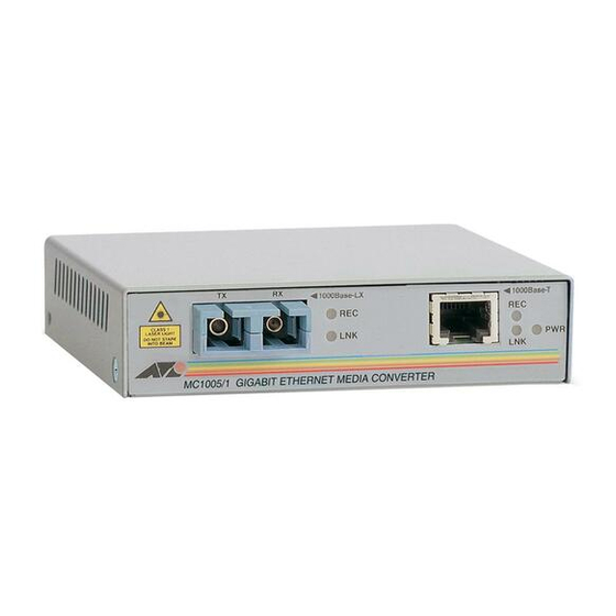
Fiber Optic Port The 1000Base-SX port on the AT-MC1004 media converter has an SC connector and is designed to operate with multimode fiber optic cabling. This port has a maximum operating distance of 550 meters (1,804 feet) using 62.5/ 125 micron multimode fiber optic cable. -
Page 14: Status Leds
MDI to MDI, you use a crossover cable. The AT-MC1004 and AT-MC1005/x Series Gigabit Media Converters feature automatic MDI/MDI-X. Each port automatically determines the configuration of the port on the device to which it is connected and then configures itself appropriately. -
Page 15: External Ac/Dc Power Adapter
AT-MC1004 and AT-MC1005/x Series Installation Guide External AC/DC Power Adapter An external AC/DC power adapter is included with the media converter for desktop operation (see Figure 3). The power adapter supplies 12V DC to the media converter. Allied Telesyn supplies an approved safety compliant AC power adapter for the 120 and 240V AC versions with an unregulated output of 12V DC at 1 A. -
Page 16: Network Topologies
Network Topologies The AT-MC1004 and AT-MC1005/x Series Gigabit Ethernet Media Converters can be used in two different topologies: standalone and back-to-back. Both types of topologies are described below. Standalone Topology A standalone topology uses only one media converter between the end-nodes. -
Page 17: Back-To-Back Topology
AT-MC1004 and AT-MC1005/x Series Installation Guide Back-to-Back Topology In some network configurations you may want to interconnect two media converters in what is referred to as a back-to-back topology. In this topology, the media converters not only extend the distance of your network but also convert the fiber optic cable from twisted pair to fiber optic and back again. -
Page 19: Installing The Media Converter
Make sure the following items are included in your media converter package. If any item is missing or damaged, contact your Allied Telesyn sales representative. One AT-MC1004 or AT-MC1005/x Series Gigabit Ethernet Media Converter Four protective feet (for desktop use only) -
Page 20: Selecting A Site
Table 4 Fiber Optic Cabling Specifications Model Cable Maximum Maximum Operating Allowable Loss Distance Budget AT-MC1004 50/125 or 62.5/125 micron 550 m (1,804 ft) 8.5 dB at 850 nm multimode AT-MC1005/1 9/125 micron single-mode 10 km (6.2 mi) 17 dB at 1310 nm... -
Page 21: Reviewing Safety Guidelines
AT-MC1004 and AT-MC1005/x Series Installation Guide Reviewing Safety Guidelines Please review the following safety guidelines before you begin to install the media converter. Warning Class 1 laser device. Warning Do not stare into the laser beam. Warning Electric Shock Hazard: To prevent electric shock, do not remove the cover. -
Page 22: Installing The Media Converter
Installing the Media Converter The following procedure explains how to install the media converter in your network. Note When two media converters are connected back-to-back with no twisted pair cables connected, the LNK LEDs on the fiber port may flash. This is normal and will not affect the normal operation of the units. -
Page 23: Warranty Registration
AT-MC1004 and AT-MC1005/x Series Installation Guide Plug the AC/DC power adapter into an appropriate AC power outlet and insert the power plug into the DC receptacle located on the back of the unit. This step does not apply if you installed the unit in an AT-MCR12 chassis. -
Page 25: Chapter 3 Troubleshooting
Installing a redundant power supply is recommended if the chassis is fully loaded with (a combination of) AT-MC1004 or AT-MC1005/x Series Media Converters. Verify that the power outlet has power by connecting another device to it. - Page 26 If the LNK LED for the fiber optic port is OFF, do the following: Verify that the end-node connected to the port is ON and is operating properly. Check that the fiber optic cable is securely connected to the fiber optic port on the media converter and on the remote end-node.
-
Page 27: Technical Specifications
Appendix A Technical Specifications Physical Dimensions: W x D x H 10.5 cm x 9.5 cm x 2.5 cm (4.125 in x 3.75 in x 1.0 in) Weight: 294 g (10.3 oz) Temperature Maximum Operating: 0° C to 40° C (32° F to 104° F) Maximum Storage: -25°... -
Page 28: Fiber Optic Port Specifications
Table 5 Fiber Optic Port Specifications Model Cable Transmitter Optical Minimum Output Power Wavelength Receiver (dBm) (nm) Sensitivity (dBm) AT-MC1004 50/125 or 62.5/125 -4.0 to -9.5 -17.0 micron multimode AT-MC1005/1 9/125 micron -3.0 to -9.0 1310 -20.0 single-mode AT-MC1005/2 9/125 micron -4.0 to 1.0... -
Page 29: Pinout Assignments
AT-MC1004 and AT-MC1005/x Series Installation Guide Pinout Assignments Figure 8 shows the pin assignments of the media converter’s RJ-45 port. Pin 1 Pin 8 Figure 8 RJ-45 Pin Assignments Table 7 lists the RJ-45 connector pins and their signals for 1000Base-T. -
Page 31: Translated Safety Statements
Appendix B Translated Safety Statements Important: This appendix contains multiple-language translations for the safety statements in this guide. Wichtig: Dieser Anhang enthält Übersetzungen der in diesem Handbuch enthaltenen Sicherheitshinweise in mehreren Sprachen. Vigtigt: Dette tillæg indeholder oversættelser i flere sprog af sikkerhedsadvarslerne i denne håndbog. - Page 32 408-730-0950 Declares that the product: Gigabit Ethernet Media Converters Model Numbers: AT-MC1004, AT-MC1005/1, AT-MC1005/2, AT-MC1005/3, AT-MC1005/4 This product complies with FCC Part 15B, Class B Limits: This device complies with part 15 of the FCC Rules. Operation is subject to the following two conditions: (1) This device must not cause harmful interference, and (2) this device must accept any interference received, including interference that may cause undesired operation.
- Page 33 AT-MC1004 and AT-MC1005/x Series Installation Guide Electrical Safety EN60950, UL1950, CSA 950 Laser EN60825 Safety Warning: Class 1 Laser product. Warning: Do not stare into the laser beam. Electrical Notices Warning: ELECTRIC SHOCK HAZARD To prevent ELECTRIC shock, do not remove the cover. No user-serviceable parts inside.
- Page 34 Gefahr Durch Blitzschlag Gefahr: Keine Arbeiten am Gerät oder an den Kabeln während eines Gewitters ausführen. ! 10 Vorsicht: Das netzkabel dient zum trennen der stromversorgung. Zur trennung vom netz, kabel aus der steckdose ziehen. ! 11 Steckbares Gerät: Die Anschlußbuchse sollte in der Nähe der Einrichtung angebracht werden und leicht zugänglich sein."...
- Page 35 AT-MC1004 and AT-MC1005/x Series Installation Guide Eisen: Dit product voldoet aan de volgende eisen. RFI Emissie EN55022 Klasse B Waarschuwing: Binnenshuis kan dit product radiostoring veroorzaken, in welk geval de gebruiker verplicht kan worden om gepaste maatregelen te nemen. Immuniteit...
- Page 36 Sécurité Attention: Producit laser di classe 1. Attention: Ne pas fixer le faisceau des yeux. Information Sur Les Risques Électriques Avertissement: DANGER D’ÉLECTROCUTION Pour éviter toute ÉLECTROCUTION, ne pas ôter le revêtement protecteur du matériel. Ce matériel ne contient aucun élément réparable par l’utilisateur.
- Page 37 AT-MC1004 and AT-MC1005/x Series Installation Guide ! 10 Huomautus: Virtajohtoa käytetään virrankatkaisulaitteena. Virta katkaistaan irrottamalla virtajohto. ! 11 Pistorasiaan kytkettävä laite; pistorasia on asennettava laitteen lähelle ja siihen on oltava esteetön pääsy." ! 12 Huomautus: Ilmavaihtoreikiä ei pidä tukkia ja niillä täytyy olla vapaa yhteys ympäröivään huoneilmaan, jotta ilmanvaihto tapahtuisi.
- Page 38 Sikkerhetsnormer: Dette produktet tilfredsstiller følgende sikkerhetsnormer. RFI stråling EN55022 Klasse B Advarsel: Hvis dette produktet benyttes til privat bruk, kan produktet forårsake radioforstyrrelse. Hvis dette skjer, må brukeren ta de nødvendige forholdsregler. Immunitet EN55024 Elektrisk sikkerhet EN60950, UL1950, CSA 950 Laser EN60825 Sikkerhet...
- Page 39 AT-MC1004 and AT-MC1005/x Series Installation Guide Aviso: Não olhe fixamente para o raio. Avisos Sobre Características Elétricas Atenção: PERIGO DE CHOQUE ELÉTRICO Para evitar CHOQUE ELÉTRICO, não retire a tampa. Não contém peças que possam ser consertadas pelo usuário. Este aparelho contém VOLTAGENS PERIGOSAS e só...
- Page 40 ! 10 Atencion: El cable de alimentacion se usa como un dispositivo de desconexion. Para desactivar el equipo, desconecte el cable de alimentación. ! 11 Equipo Conectable, el tomacorriente se debe instalar cerca del equipo, en un lugar con acceso fácil". ! 12 Atencion: Las aberturas para ventilación no deberán bloquearse y deberán tener acceso libre al aire ambiental de la sala para su enfriamiento.
Need help?
Do you have a question about the AT-MC1004 and is the answer not in the manual?
Questions and answers