Table of Contents
Advertisement
Quick Links
Advertisement
Table of Contents

Related Manuals for Allied Telesis AT-MCR1


Summary of Contents for Allied Telesis AT-MCR1
-
Page 1: Media Converter
Media Converter Chassis AT-MCR1 Installation Guide 613-000687 Rev B... - Page 2 All rights reserved. No part of this publication may be reproduced without prior written permission from Allied Telesis, Inc. Allied Telesis is a trademark of Allied Telesis, Inc. All other product names, company names, logos or other designations mentioned herein are trademarks or registered trademarks of their respective owners.
-
Page 3: Declaration Of Conformity
Compliance Statement Standards: This product meets the following standards. U.S. Federal Communications Commission Declaration of Conformity Manufacturer Name: Allied Telesis, Inc. Declares that the product: Media Converter Chassis Model Numbers: AT-MCR1 This product complies with FCC Part 15B, Class B Limits: This device complies with part 15 of the FCC Rules. - Page 4 Electrical Safety EN60950 (TUV), UL 60950-1 ( CSA C22.2 Translated Safety Statements Important: The indicates that a translation of the safety statement is available in a PDF document titled “Translated Safety Statements” posted on the Allied Telesis website at www.alliedtelesis.com.
-
Page 5: Table Of Contents
Contents Preface ..................7 Safety Symbols Used in this Document ........8 Where to Find Web-based Guides ..........9 Contacting Allied Telesis .............10 Online Support ..............10 Email and Telephone Support..........10 Warranty ................10 Returning Products..............10 Sales or Corporate Information ...........11 Chapter 1: Overview ..............13 Key Features ................14... - Page 6 Contents Temperature ................45 Electrical Rating (for AC version only).........45 Safety and Electromagnetic Emissions Certifications ....46 Compliance Standards ..............46...
-
Page 7: Preface
Preface This guide contains instructions on how to install an AT-MCR1 Media Converter Chassis. This preface contains the following sections: “Safety Symbols Used in this Document” on page 8 “Where to Find Web-based Guides” on page 9 “Contacting Allied Telesis” on page 10... -
Page 8: Safety Symbols Used In This Document
Preface Safety Symbols Used in this Document This document uses the safety symbols in Table 1. Table 1. Safety Symbols Symbol Meaning Description Caution Performing or omitting a specific action may result in equipment damage or loss of data Warning Performing or omitting a specific action may result in electrical shock. -
Page 9: Where To Find Web-Based Guides
AT-MCR1 Media Converter Chassis Installation Guide Where to Find Web-based Guides The installation and user guides for all Allied Telesis products are available in portable document format (PDF) on our web site at www.alliedtelesis.com. You can view the documents online or... -
Page 10: Contacting Allied Telesis
Select your country from the list displayed on the website, then select the appropriate menu tab. Warranty For hardware warranty information, refer to the Allied Telesis web site: www.alliedtelesis.com/support/warranty. Select your country from the list displayed on the website, then select the appropriate menu tab. -
Page 11: Sales Or Corporate Information
AT-MCR1 Media Converter Chassis Installation Guide tab. Sales or Corporate Information You can contact Allied Telesis for sales or corporate information on our web site: www.alliedtelesis.com. To find the contact information for your country, select Contact Us -> Worldwide Contacts. - Page 12 Preface...
-
Page 13: Chapter 1 Overview
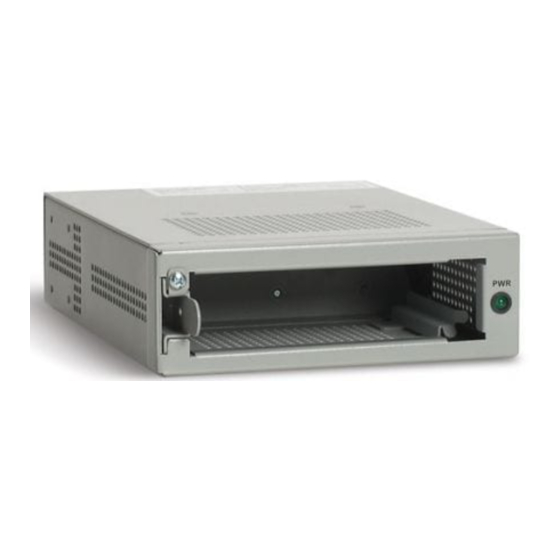
Chapter 1 Overview The AT-MCR1, shown in Figure 1, is a chassis with an internal power supply designed to house one Allied Telesis media converter. The AT-MCR1 chassis provides convenient installation options: on a desktop, mounted under a table, placed on the wall, or installed in an industry standard 19”... -
Page 14: Key Features
Chapter 1: Overview Key Features The AT-MCR1 chassis has the following features: LED for unit status One slot for an ATI standard media converter Internal AC/DC power supply Desktop, wall, under table, or rack mount installation Status LEDs Refer to Table 2 for a description of the chassis LED. -
Page 15: Chapter 2: Installation
Chapter 2 Installation This chapter contains the following sections: “Reviewing Safety Precautions” on page 16 “Verifying the Package Contents” on page 20 “Selecting a Site” on page 21 “Installing a Media Converter in the Chassis” on page 22 “Installing the Chassis On a Table or Desktop (AC Models Only)”... -
Page 16: Reviewing Safety Precautions
Note indicates that a translation of the safety statement is available in a PDF document titled “Translated Safety Statements” on the Allied Telesis website at www.alliedtelesis.com. Warning: Class 1 Laser product. Warning: Do not work on equipment or cables during periods of lightning activity. - Page 17 AT-MCR1 Media Converter Chassis Installation Guide Caution: Air vents must not be blocked and must have free access to the room ambient air for cooling. Warning: Operating Temperature. This product is designed for a maximum ambient temperature of 40° degrees C.
- Page 18 Chapter 2: Installation Warning: Check to see if there are any exposed copper strands coming from the installed wires. When this installation is done correctly there should be no exposed copper wire strands extending from the terminal block. Any exposed wiring can conduct harmful levels of electricity to persons touching the wires.
- Page 19 AT-MCR1 Media Converter Chassis Installation Guide Warning: Reliable earthing of rack-mounted equipment should be maintained. Particular attention should be given to supply connections other than direct connections to the branch circuits (e.g., use of power strips).
-
Page 20: Verifying The Package Contents
Chapter 2: Installation Verifying the Package Contents Make sure the following items are included in your package. If any item is missing or damaged, contact your Allied Telesis sales representative for assistance. One AT-MCR1 Media Converter Chassis with a mounting... -
Page 21: Selecting A Site
AT-MCR1 Media Converter Chassis Installation Guide Selecting a Site Be sure to observe the following requirements when choosing a site for your chassis. Make sure you are placing the chassis in a dust-free and moisture-free environment. Do not block the ventilation openings on the unit. Allow at least 10 centimeters (4 inches) of space at the front and back of the unit for ventilation. -
Page 22: Installing A Media Converter In The Chassis
Chapter 2: Installation Installing a Media Converter in the Chassis To install a media converter in the AT-MCR1 chassis, perform the following procedure: Remove all components from the shipping packages. Note Store the packaging material in a safe place. You must use the original shipping material if you need to return the unit to Allied Telesis. - Page 23 AT-MCR1 Media Converter Chassis Installation Guide Align the mounting rail with the media converter, placing the two pins into the front and rear air vents, as shown in Figure 1049 Figure 4. Aligning the Mounting Rail with the Media Converter...
- Page 24 Chapter 2: Installation Press gently on the media converter to seat the power plug into the chassis. Tighten the captive screw on the mounting rail to secure the media converter in the chassis, as shown in Figure 6 1278 Figure 6. Tightening the Captive Screw on the Mounting Rail...
-
Page 25: Installing The Chassis On A Table Or Desktop (Ac Models Only)
AT-MCR1 Media Converter Chassis Installation Guide Installing the Chassis On a Table or Desktop (AC Models Only) To install the chassis on a table or desktop, perform the following procedure: Turn the AT-MCR1 chassis over. Attach the four protective rubber feet to the bottom of the chassis, as shown in Figure 7. -
Page 26: Installing The Chassis Under A Table (Ac Models Only)
Chapter 2: Installation Installing the Chassis Under a Table (AC Models Only) The AT-MCR1 chassis can be mounted under a table using the mounting brackets shipped with the chassis. Note Make sure that the under-table location provides easy access for installing the twisted pair, fiber optic, and power cables to and from the chassis. - Page 27 AT-MCR1 Media Converter Chassis Installation Guide Attach one mounting bracket (provided) to each side of the chassis using the bracket mounting screws (provided), as shown in Figure 8. 1052 Figure 8. Attaching Brackets for Under-Table Installation Position and mount the top of the chassis under the table...
- Page 28 Chapter 2: Installation Make sure that the chassis is securely mounted under the table. Power the chassis on following the instructions in “Powering On an AC-Powered Chassis” on page 34.
-
Page 29: Mounting The Chassis On The Wall
Note If the AT-MCR1 is to be mounted onto a concrete wall, make sure to drill the required holes with the drill bit using the drill bit size that is suitable for the plastic wall anchors. Then, insert the plastic wall anchors. - Page 30 Chapter 2: Installation Turn the chassis over and attach a mounting bracket (provided) to each side of the chassis using the bracket mounting screws (provided), as shown in Figure 10. 1052 Figure 10. Attaching the Brackets for Wall Mounting Position and mount the chassis on the wall using the mounting screws, as shown in Figure 11.
- Page 31 AT-MCR1 Media Converter Chassis Installation Guide Make sure that the chassis is securely mounted onto the wall. Install the cables. For cabling instructions, refer to the installation guide that is shipped with the Allied Telesis media converter. Power on the chassis, referring to one of the following sections: “Powering On an AC-Powered Chassis”...
-
Page 32: Installing The Chassis In A Rack
If attached, remove the rubber feet, data cables, and power cord from the chassis. Attach one mounting bracket (provided) to the right side of the AT-MCR1 chassis using the bracket mounting screws (provided), as shown in Figure 12. 1055 Figure 12. Attaching Bracket for Rack Mounting... - Page 33 AT-MCR1 Media Converter Chassis Installation Guide Mount the AT-MCR1 chassis on a 19” or 23” rack using the rackmounting screws (not provided), as shown in Figure 13. 1056 Figure 13. Mounting the Chassis in a Rack Make sure that the chassis is securely mounted in the rack.
-
Page 34: Powering On An Ac-Powered Chassis
Chapter 2: Installation Powering On an AC-Powered Chassis To apply power to an AC-powered AT-MCR1 chassis, perform the following procedure: Install the retaining clip on the chassis, as shown in Figure 14. 1022 Figure 14. Installing the Power Cord Retaining Clip Position the power cord retaining clip in the up position, as shown in Figure 15. - Page 35 AT-MCR1 Media Converter Chassis Installation Guide Plug the power cord into the power connector on the back of the chassis, as shown in Figure 16. 1057 Figure 16. Plugging the Power Cord into the Chassis Secure the cord by lowering the power cord retaining clip, as shown in Figure 17.
- Page 36 The chassis runs a series of self-diagnostic tests, which take a few seconds to perform. After the self tests are complete, the chassis is ready for normal network operations. For cabling instructions, refer to the installation guide that is shipped with the Allied Telesis media converter.
-
Page 37: Wiring And Powering On A Dc-Powered Chassis
AT-MCR1 Media Converter Chassis Installation Guide Wiring and Powering On a DC-Powered Chassis To wire and power on a DC-powered chassis, perform the following procedure: Warning As a safety precaution, install a circuit breaker with a minimum value of 15 Amps between the equipment and the DC power source. - Page 38 Chapter 2: Installation A tray cable is required to connect the power source if the chassis is powered by centralized DC power. The tray cable must be an UL listed Type TC tray cable and rated at 600 V and 90 degree C, with three conductors, minimum 14 AWG. On the back panel of the chassis is a DC terminal block, starting from the left side of the terminal block, identify the positive, frame ground, and negative terminals, using the...
- Page 39 AT-MCR1 Media Converter Chassis Installation Guide Warning Do not strip more than the recommended amount of wire. Stripping more than the recommended amount can create a safety hazard by leaving exposed wire on the terminal block after installation. Connect the frame ground wire to the terminal marked with...
- Page 40 Chapter 2: Installation Connect the negative feed wire to the terminal block marked (-). Warning Check to see if there are any exposed copper strands coming from the installed wires. When this installation is done correctly there should be no exposed copper wire strands extending from the terminal block.
- Page 41 AT-MCR1 Media Converter Chassis Installation Guide For cabling instructions, refer to the installation guide that is shipped with the Allied Telesis media converter.
-
Page 42: Warranty Registration
Chapter 2: Installation Warranty Registration When you have finished installing the product, register your product by completing the enclosed warranty card and sending it in. You can also fill out the registration online by selecting “Warranties” under “Support & Services” from www.alliedtelesis.com. -
Page 43: Chapter 3 Troubleshooting
Verify that the chassis and end-nodes are operating with the same duplex mode. If you are still experiencing problems after testing and troubleshooting the installation, refer to “Contacting Allied Telesis” on page 10. For support information, visit our web site at www.alliedtelesis.com. - Page 44 Chapter 3: Troubleshooting...
-
Page 45: Appendix A: Technical Specifications
Appendix A Technical Specifications Physical Dimensions: W x D x H 130 mm x 166 mm x 44 mm (5.118 in x 6.535 in x 1.732 in) Weight: .27 kg (0.60 lbs) Temperature Operating Temperature: 0° C to 40° C (32°... -
Page 46: Safety And Electromagnetic Emissions Certifications
Appendix A: Technical Specifications Safety and Electromagnetic Emissions Certifications RFI Emissions FCC Part 15 Class B Immunity EN55024 Electrical Safety EN60950 (TUV), CE Compliance Standards RoHS Compliant...
Need help?
Do you have a question about the AT-MCR1 and is the answer not in the manual?
Questions and answers