
Related Manuals for Allied Telesis AT-MCF106ST


Summary of Contents for Allied Telesis AT-MCF106ST
- Page 1 AT-MCF106ST, SC, MT AT-MCF106VF, SM, LH AT-MCF112ST, SC, MT AT-MCF112VF, SM, LH Multichannel Ethernet Media Converters Installation Guide PN 613-10829-00 Rev C...
- Page 2 Copyright 2004 Allied Telesyn, Inc. www.alliedtelesyn.com All rights reserved. No part of this publication may be reproduced without prior written permission from Allied Telesyn International, Corp. Ethernet is a registered trademark of Xerox Corporation. All other product names, company names, logos or other designations mentioned herein are trademarks or registered trademarks of their respective owners.
-
Page 3: Electrical Safety And Emission Statements
Electrical Safety and Emission Statements Standards: This product meets the following standards U.S. Federal Communications Commission RADIATED ENERGY Note: This equipment has been tested and found to comply with the limits for a Class A digital device pursuant to Part 15 of FCC Rules. These limits are designed to provide reasonable protection against harmful interference when the equipment is operated in a commercial environment. - Page 4 Electrical Safety and Emission Statements IMPORTANTE: O Anexo B conte ´ m adverte ˆ ncias de seguranc ¸ a traduzidas para instalar este equipamento. Quando vir o sı ´ mbolo , leia a adverte ˆ ncia de seguranc ¸ a traduzida no seu idioma no Anexo A.
-
Page 5: Table Of Contents
Contents Electrical Safety and Emission Statements..........iii Contents ......................v Preface......................vii Where to Find Related Guides................. vii Document Conventions ..................vii Contacting Allied Telesyn ................viii Online Support ..................viii E-mail and Telephone Support..............viii Returning Products ..................viii For Sales or Corporate Information ............viii Chapter 1 Overview ...................... -
Page 6: Contents
Contents Chapter 2 Installation ..................... 13 Selecting a Site for the Media Converter ............13 Checking the Media Converter Package ............14 Planning the Installation ................. 14 Reviewing Safety Precautions ................. 16 Installing the Media Converter as a Standalone Unit ........18 Installing the Media Converter in a Rack............ -
Page 7: Preface
Preface This guide contains instructions on how to install and configure the AT-MCF106xx and AT-MCF112xx Series Multichannel Ethernet Media Converters. Where to Find Related Guides The Allied Telesyn web site at www.alliedtelesyn.com offers you an easy way to access the most recent documentation, software, and technical information for all of our products. -
Page 8: Contacting Allied Telesyn
Preface Contacting Allied Telesyn This section provides Allied Telesyn contact information for technical support as well as sales or corporate information. Online Support You can request technical support online by accessing the Allied Telesyn Knowledge Base from the following web site: http://kb.alliedtelesyn.com. You can use the Knowledge Base to submit questions to our technical support staff and review answers to previously asked questions. -
Page 9: Chapter 1 Overview
Chapter 1 Overview The Ethernet AT-MCF106xx and the AT-MCF112xx Series Multichannel Media Converters are designed to extend the reach of your network by converting your twisted pair cabling into fiber optic cabling. These products, which transfer Ethernet data between 100Base-TX and 100Base-FX technologies, enable you to quickly and easily interconnect the nodes in your network to distances of 2 kilometers (1.24 miles) to 40 kilometers (24.8 miles), depending on the model. -
Page 10: System Models
Model Number of Type of Type of Maximum Media Fiber Optic Fiber Optic Distance Converter Connector Cabling Channels AT-MCF106ST Multimode 2 km (1.24 mi) AT-MCF106SC Multimode 2 km (1.24 mi) AT-MCF106MT MT-RJ Multimode 2 km (1.24 mi) AT-MCF106VF VF-45 Multimode 2 km (1.24 mi) -
Page 11: Front And Back Components
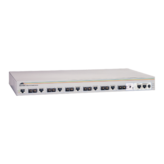
AT-MCF106xx and AT-MCF112xx Installation Guide Front and Back Components This section describes the features and components of the AT-MCF106xx and AT-MCF112xx Series Multichannel Media Converters. Figure 1 illustrates the front panel of an AT-MCF106xx unit. MCF106SC 100Base-TX/FX Media Converter MANAGEMENT NORM P OW ER T-LNK... -
Page 12: Twisted Pair And Fiber Optic Ports
Overview Twisted Pair and Fiber Optic Ports The twisted pair and fiber optic ports on the unit are paired together (see Figure 3). Each pair is referred to as a “channel” and each channel functions as an independent media converter. The AT-MCF106xx Multichannel Media Converter has six channels while the AT-MCF112xx Series Multichannel Media Converter has twelve channels. -
Page 13: Status Leds
AT-MCF106xx and AT-MCF112xx Installation Guide Status LEDs The media converter does not require any software configuration or software management. The status of the unit can be determined by viewing the LEDs on the front of the unit. Table 2 lists the functions of the power supply and Link Test switch LEDs. -
Page 14: Link Test Switch
Overview Link Test Switch The Link Test switch is a fast and easy way for you to test the integrity of the fiber optic connections to the fiber optic ports on the media converter (see Figure 4). The AT-MCF106xx unit has one Link Test switch which is used to test all six fiber optic ports on the unit. -
Page 15: Missinglink Feature
AT-MCF106xx and AT-MCF112xx Installation Guide MissingLink Feature The MissingLink feature enables the twisted pair and fiber optic ports of ™ each channel on the media converter to pass the “Link” status of their connections to each other. When a channel detects a problem with one of the ports, such as the loss of connection to a node, the channel shuts down the connection to the other port of the channel, thus notifying the node that the connection has been lost. -
Page 16: Duplex Mode Dip Switches
Overview Duplex Mode DIP Switches The AT-MCF106xx and AT-MCF112xx Series Multichannel Media Converters include DIP switches (Figure 1) on the front panel for controlling the duplex mode of the individual media converter channels. You use the DIP switches to set each channel to either half- or full-duplex operation. The AT-MCF106xx Series Multichannel Media Converter has one set of DIP switches while the AT-MCF112xx Series has two sets of switches. -
Page 17: Reset Button
AT-MCF106xx and AT-MCF112xx Installation Guide Reset Button The Reset button allows you to reset the ports on the unit. You might need to reset the ports after completing the installation or after adding or swapping a power supply. You must reset the unit after a power disruption or whenever a general power failure status is observed. -
Page 18: 10Base-T And Rs-232 Ports
Overview 10Base-T and RS-232 Ports These ports (see Figure 7) are reserved for future development. ANAGEMENT RS232 10Base-T NORM MCF112SC 100Base-TX/FX Media Converter T-LNK TE ST TEST F-LNK MANAGEMENT Active NORM P O WE R BCKP MAIN 7 8 9 10 11 12 TE ST TEST Ready... - Page 19 AT-MCF106xx and AT-MCF112xx Installation Guide AT-8224XL Ethernet Switch 10 BA SE-T / 1 00B ASE-TX FAST ETH ERN ET SW ITCH 10B ASE- T / 10 0BASE-TX PORT ACTI VITY RS-2 32 S TA T US 13 X 100 M L INK / ACTIVITY 10M LINK / AC TIVITY...
-
Page 21: Chapter 2 Installation
Chapter 2 Installation The following sections explain how to install the unit onto your network. The unit can be installed as a standalone system (such as on a desk) or in a standard 19-inch rack. Selecting a Site for the Media Converter Be sure to observe the following requirements when choosing a site for your media converter: Select a site that is dust-free and moisture-free. -
Page 22: Checking The Media Converter Package
Installation Checking the Media Converter Package Your media converter package should include the following items: One AT-MCF106xx or AT-MCF112xx Multichannel Media Converter Rack mounting kit One AC power cord Four self-adhesive rubber feet This installation guide Warranty card If any of the above items are missing or damaged, contact your Allied Telesyn representative. - Page 23 AT-MCF106xx and AT-MCF112xx Installation Guide Use a straight-through cable to connect a hub or switch to a twisted pair port on the unit. Use a crossover cable to connect a workstation to a twisted pair port on the unit. Refer to Table 5 for the fiber optic cabling specifications. Table 5 Fiber Optic Cabling Specifications Specifications Media...
-
Page 24: Reviewing Safety Precautions
Check the attenuation on the fiber optic cabling after installation. Refer to Table 6 for the maximum allowable loss budget. Table 6 Maximum Allowable Loss Budget Model Maximum Allowable Loss Wavelength Budget AT-MCF106ST 20 dB (MMF) 1310 nm AT-MCF106SC 20 dB (MMF) 1310 nm AT-MCF106MT... - Page 25 AT-MCF106xx and AT-MCF112xx Installation Guide Warning Electric Shock Hazard: To prevent electric shock, do not remove the cover. There are no user-serviceable parts inside. The unit contains hazardous voltages and should only be opened by a trained and qualified technician. To avoid the possibility of ELECTRIC SHOCK, disconnect electric power to the product before connecting or disconnecting the LAN cables.
-
Page 26: Installing The Media Converter As A Standalone Unit
Installation Installing the Media Converter as a Standalone Unit The media converter can be installed as a standalone unit (for instance, on a table) or in a standard 19-inch rack. To install the unit in a rack, refer to “Installing the Media Converter in a Rack” on page 20. To install the media converter as a standalone unit, perform these steps: Remove all equipment from the shipping package and store the package in a safe place. - Page 27 AT-MCF106xx and AT-MCF112xx Installation Guide Caution When connecting a power cord, you should always plug the power cord into the media converter first. Only after it has been securely installed should you plug the power cord into a power source. Warning Power cord is used as a disconnection device: To de-energize equipment, disconnect the power cord.
-
Page 28: Installing The Media Converter In A Rack
Installation If one end node is capable of only half-duplex mode while the other end node will auto-negotiate the duplex mode, set the channel setting to half-duplex. (Failure to set the channel to half-duplex in this situation will result in what is referred to as a classic duplex mode mismatch, where one node will operate in half-duplex while the other node will operate in full-duplex. - Page 29 AT-MCF106xx and AT-MCF112xx Installation Guide Insert the three screws provided with the unit and tighten with a suitable screwdriver, as shown in Figure 9. Figure 9. Installing the Mounting Bracket Repeat Step 4 and Step 5 to install the remaining bracket on the other side of the unit.
-
Page 30: Verifying The Installation
Installation the media converter’s two power cords to power outlets that are on different circuits. This will protect the unit from a loss of power should a power circuit fail. Remove the dust covers from the fiber optic ports. Laser Do not stare into the laser beam. - Page 31 AT-MCF106xx and AT-MCF112xx Installation Guide If you installed an optional redundant power supply, check that the BCKP LED is a steady green. Check to be sure that the fans for the main power supply and the optional redundant power supply, if installed, are operating. Set the Link Test switch to the Test position.
-
Page 33: Chapter 3 Troubleshooting
Chapter 3 Troubleshooting This section contains guidelines for troubleshooting the media converter in the event a problem occurs. If the Main LED is OFF, check the following: Check to be sure that the power cord for the main power supply is securely connected to the power supply and the power outlet. -
Page 34: Resetting The Unit
Troubleshooting If the T-LNK LED for a twisted pair port is OFF, check the following: Check to be sure the node connected to the port is powered ON. Check to be sure that the twisted pair cable is securely connected to both the port on the media converter and the node. -
Page 35: Technical Specifications
Appendix A Technical Specifications Physical Specifications Dimensions: W x H x D 44.1 cm x 26.5 cm x 4.4 cm (17.3 in x 10.4 in x 1.75 in) Weight: 4.2 kg (9.2 lbs) Environmental Specifications Operating Temperature: 0° C to 40° C (32° F to 104° F) Storage Temperature: -25°... -
Page 36: Safety And Electromagnetic Emissions Certifications
Technical Specifications Safety and Electromagnetic Emissions Certifications EMI/RFI: FCC Class A, EN55022 Class A, VCCI Class A, ICES Class A Electrical Safety: EN60950, UL1950, CSA950 Immunity: EN50082-1 Laser: EN60825 Pinout Assignments Figure 10 shows the pinout assignments for the RJ-45 connector. Figure 10 RJ-45 Pin Assignments Table 7 lists the RJ-45 connector pins and their signals used in Port 1 - Port 4 when these port are operating in either MDI or MDI-X configuration. -
Page 37: Translated Safety And Emission Information
Appendix B Translated Safety and Emission Information Important: This appendix contains multiple-language translations for the safety statements in this guide. Wichtig: Dieser Anhang enthält Übersetzungen der in diesem Handbuch enthaltenen Sicherheitshinweise in mehreren Sprachen. Vigtigt: Dette tillæg indeholder oversættelser i flere sprog af sikkerhedsadvarslerne i denne håndbog. - Page 38 Translated Safety and Emission Information Standards: This product meets the following standards: U.S. Federal Communications Commission RADIATED ENERGY Note: This equipment has been tested and found to comply with the limits for a Class A digital device pursuant to Part 15 of FCC Rules. These limits are designed to provide reasonable protection against harmful interference when the equipment is operated in a commercial environment.
- Page 39 AT-MCF106xx and AT-MCF112xx Installation Guide 11 ELECTRICAL - TYPE CLASS 1 EQUIPMENT THIS EQUIPMENT MUST BE EARTHED. Power plug must be connected to a properly wired earth ground socket outlet. An improperly wired socket outlet could place hazardous voltages on accessible metal parts. ...
- Page 40 Translated Safety and Emission Information Normen: Dieses Produkt erfüllt die Anforderungen der nachfolgenden Normen. 1 Hochfrequenzstörung EN55022 Klasse A 2 WARNUNG: Bei Verwendung zu Hause kann dieses Produkt Funkstörungen hervorrufen. In diesem Fall müßte der Anwender angemessene Gegenmaßnahmen ergreifen.
- Page 41 AT-MCF106xx and AT-MCF112xx Installation Guide Standarder: Dette produkt tilfredsstiller de følgende standarder. 1 Radiofrekvens forstyrrelsesemission EN55022 Klasse A 2 ADVARSEL: I et hjemligt miljø kunne dette produkt forårsage radio forstyrrelse. Bliver det tilfældet, påkræves brugeren muligvis at tage tilstrækkelige foranstaltninger.
- Page 42 Translated Safety and Emission Information Eisen: Dit product voldoet aan de volgende eisen. 1 RFI Emissie EN55022 Klasse A 2 WAARSCHUWING: Binnenshuis kan dit product radiostoring veroorzaken, in welk geval de gebruiker verplicht kan worden om gepaste maatregelen te nemen. ...
- Page 43 AT-MCF106xx and AT-MCF112xx Installation Guide Normes: ce produit est conforme aux normes de suivantes: 1 Emission d’interférences radioélectriquesEN55022 Classe A 2 MISE EN GARDE : dans un environnement domestique, ce produit peut provoquer des interférences radioélectriques. Auquel cas, l’utilisateur devra prendre les mesures adéquates.
- Page 44 Translated Safety and Emission Information Standardit: Tämä tuote on seuraavien standardien mukainen. 1 Radioaaltojen häirintä EN55022 Luokka A 2 VAROITUS: Kotiolosuhteissa tämä laite voi aiheuttaa radioaaltojen häiröitä, missä tapauksessa laitteen käyttäjän on mahdollisesti ryhdyttävä tarpeellisiin toimenpiteisiin. 3 Kestävyys EN50082-1 ...
- Page 45 AT-MCF106xx and AT-MCF112xx Installation Guide Standard: Questo prodotto è conforme ai seguenti standard. Emissione RFI (interferenza di radiofrequenza) EN55022 Classe A 1 AVVERTENZA: in ambiente domestico questo prodotto potrebbe causare radio 2 interferenza. In questo caso potrebbe richiedersi all’utente di prendere gli adeguati provvedimenti.
- Page 46 Translated Safety and Emission Information Sikkerhetsnormer: Dette produktet tilfredsstiller følgende sikkerhetsnormer. RFI stråling EN55022 Klasse A 1 ADVARSEL: Hvis dette produktet benyttes til privat bruk, kan produktet forårsake 2 radioforstyrrelse. Hvis dette skjer, må brukeren ta de nødvendige forholdsregler. Immunitet EN50082-1 ...
- Page 47 AT-MCF106xx and AT-MCF112xx Installation Guide Padrões: Este produto atende aos seguintes padrões. Emissão de interferência de radiofrequênciaEN55022 Classe A 1 AVISO: Num ambiente doméstico este produto pode causar interferência na 2 radiorrecepção e, neste caso, pode ser necessário que o utente tome as medidas adequadas.
- Page 48 Estándares: Este producto cumple con los siguientes estándares. Emisión RFI EN55022 Clase A 1 ADVERTENCIA: en un entorno doméstico, este producto puede causar 2 radiointerferencias, en cuyo caso, puede requerirse del usuario que tome las medidas que sean convenientes al respecto. Inmunidad EN50082-1 ...
- Page 49 AT-MCF106xx and AT-MCF112xx Installation Guide Standarder: Denna produkt uppfyller följande standarder. Radiostörning EN55022 Klass A 1 VARNING: Denna produkt kan ge upphov till radiostörningar i hemmet, vilket kan 2 tvinga användaren till att vidtaga erforderliga åtgärder. Immunitet EN50082-1 ...
Need help?
Do you have a question about the AT-MCF106ST and is the answer not in the manual?
Questions and answers