Table of Contents
Advertisement
Advertisement
Table of Contents

Related Manuals for Allied Telesis MMC2000/200 Series


Summary of Contents for Allied Telesis MMC2000/200 Series
- Page 1 MMC2000/200 Series Mini Switching Media Converters AT-MMC2000/SC AT-MMC2000/ST AT-MMC2000/LC AT-MMC2000/SP AT-MMC2000LX/SC AT-MMC2000LX/LC AT-MMC200/SC AT-MMC200/ST AT-MMC200/LC AT-MMC200LX/SC AT-MMC200LX/ST Installation Guide 613-002037 Rev. D...
- Page 2 Allied Telesis, Inc. has been advised of, known, or should have known, the...
- Page 3 Electrical Safety and Emissions Standards This section contains the following: “US Federal Communications Commission” “Industry Canada” “Emissions, Immunity and Electrical Safety Standards” on page 4 “Translated Safety Statements” on page 4 US Federal Communications Commission Radiated Energy Note This equipment has been tested and found to comply with the limits for a Class A digital device pursuant to Part 15 of FCC Rules.
- Page 4 Electrical Safety EN60950-1 (TUV), UL 60950-1 ( Warning Laser Safety: EN60825 Translated Safety Statements Important: The indicates that a translation of the safety statement is available in a PDF document titled Translated Safety Statements on the Allied Telesis website at www.alliedtelesis.com/support.
-
Page 5: Table Of Contents
Contents Preface................................11 Symbol Conventions ..........................12 Contacting Allied Telesis..........................13 Chapter 1 : Overview ............................. 15 Introduction ..............................16 Features .............................. 16 Twisted-Pair Port ..........................18 Auto MDI/MDI-X ..........................18 Auto-Negotiation or 100 Mbps Full-Duplex Mode................18 LEDs..............................19 Smart MissingLink™... - Page 6 Contents...
- Page 7 Figure 7: SML with Copper Connection to End Node Down....................22 Figure 8: SML with Fiber Connection Between Media Converters Down................23 Figure 9: MMC2000/200 Series Converter Rear Panel DIP Switches................. 23 Figure 10: MMC2000/200/SC Series and MMC2000/200/LX/SC Series Front Panel ............25 Figure 11: MMC2000/200/ST Series and AT-MMC200/LX/ST Front Panel ................
- Page 8 List of Figures...
- Page 9 Tables Table 1. Connecting Networks ............................16 Table 2. Media Converter LED Functional Descriptions .....................20 Table 3. Twisted-Pair Port Cabling Specifications ......................34 Table 4. Copper Connection Speed/Duplex Settings and Resulting Speed - MMC2000 ...........34 Table 5. Copper Connection Speed/Duplex Settings and Resulting Speed - AT-MMC200 ..........36 Table 6.
- Page 10 List of Tables...
-
Page 11: Preface
Preface This preface contains the following sections: “Symbol Conventions” on page 12 “Contacting Allied Telesis” on page 13 This guide contains the installation instructions for the following Mini Switching Media Converters. AT-MMC2000/SC AT-MMC2000/ST AT-MMC2000/SP AT-MMC2000/LC ... -
Page 12: Symbol Conventions
Symbol Conventions This document uses the following conventions: Note Notes provide additional information. Caution Cautions inform you that performing or omitting a specific action may result in equipment damage or loss of data. Warning Warnings inform you that performing or omitting a specific action may result in bodily injury. -
Page 13: Contacting Allied Telesis
MMC2000/200 Series Mini Switching Media Converter Installation Guide Contacting Allied Telesis If you need assistance with this product, you may contact Allied Telesis technical support by going to the Support & Services section of the Allied Telesis web site at www.alliedtelesis.com/support. You can find links for... -
Page 15: Chapter 1 : Overview
Chapter 1 Overview This chapter contains the following sections: “Introduction” on page 16 “Front and Back Panels” on page 25 “Reset the Media Converter” on page 28 ... -
Page 16: Introduction
AT-MMC200LX/SC AT-MMC200LX/ST Features Here are the key features of the MMC2000/200 Series converters: The media converter provides a smaller-sized space-saving alternative that allows enterprises to connect copper networks to fiber networks, offering a cost-effective method for integrating fiber-optic cabling into a 10/100/1000 or 10/100 UTP environment. - Page 17 MMC2000/200 Series Mini Switching Media Converter Installation Guide Table 1. Connecting Networks (Continued) Fiber-optic Port Models Copper Port Connector L1 Standard AT-MMC2000/SP SFP slot 100/1000Base-X 10/100/1000Base-T AT-MMC200/LC AT-MMC200/SC 100Base-FX AT-MMC200/ST 10/100Base-TX AT-MMC200LX/SC 100Base-LX AT-MMC200LX/ST Smart MissingLink™ (SML) Auto Negotiation and Auto MDI/MDI-X on the twisted-pair port ...
-
Page 18: Twisted-Pair Port
For the AT-MMC2000/SP model, you must purchase the SFP transceiver separately. The maximum operating distance of the AT- MMC2000/SP is dependent on the specific SFP module. For a list of supported transceivers, contact your Allied Telesis distributor or reseller. Twisted-Pair Port Here are the basic features of the twisted-pair (copper) port: IEEE 802.3u Auto-Negotiation compliant... -
Page 19: Leds
MMC2000/200 Series Mini Switching Media Converter Installation Guide When in the AUTO NEG (down) position, the twisted-pair port operates in Auto-Negotiation mode. Note 100 Mbps full-duplex mode should not be used unless absolutely necessary because forcing 100 Mbps full-duplex in most applications is likely to cause a duplex mismatch, in turn, causing poor network performance. -
Page 20: Table 2. Media Converter Led Functional Descriptions
A = Activity) Slow Blinking SML is on and detects a failure on the copper Green port or the remote fiber port when operating in a back-to-back configuration with another MMC2000/200 Series media converter. See Figure 7 on page 22. -
Page 21: Smart Missinglink™ (Sml)
MMC2000/200 Series Mini Switching Media Converter Installation Guide Smart If one of the Ethernet connections to the media converter loses link, the Smart MissingLink™ (SML) feature allows you to determine which port still MissingLink™ has a valid connection and which port requires troubleshooting. The value... -
Page 22: Sml Example Scenarios With Two Connected Media Converters
Chapter 1: Overview Figure 5 shows media converter and end node L/A LED behavior with SML enabled with a copper connection down. End Node End Node AT-MMC2000/200 Copper Cable Fiber Cable Link LED Off Link LED Blinking Copper L/A Fiber L/A LED Off LED Blinking Figure 5. -
Page 23: Enabling Sml
ON (up) position. See Figure 9. SML ON/OFF PORT 1 (In Auto Negotiation position) Figure 9. MMC2000/200 Series Converter Rear Panel DIP Switches Note For information on the FORCE 100 F/D and AUTO NEG switch, see “Auto-Negotiation or 100 Mbps Full-Duplex Mode” on page 18. - Page 24 Chapter 1: Overview Note The media converter power receptacle has a twist-and-lock barrel which is locked by turning the power cord clockwise one-quarter turn.
-
Page 25: Front And Back Panels
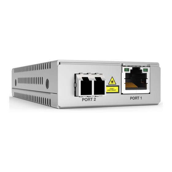
MMC2000/200 Series Mini Switching Media Converter Installation Guide Front and Back Panels Figure 10 illustrates the front panel of the MMC2000/200/SC series and MMC2000/200/LX/SC series media converters. Base-T Fiber SC TX & RX Twisted-Pair Port Ports L/A LED Fiber Port... -
Page 26: Figure 12: Mmc2000/200Lc Series And At-Mmc2000/Lx/Lc Front Panel
Chapter 1: Overview Figure 12 illustrates the front panel of the AT-MMC2000/LC, AT- MMC2000LX/LC, and AT-MMC200/LC media converters. Base-T Fiber LC TX & RX Twisted-Pair Port Ports L/A LED Fiber Port L/A LED Base-T Twisted-Pair Port Figure 12. MMC2000/200LC Series and AT-MMC2000/LX/LC Front Panel Figure 13 illustrates the front panel of the AT-MMC2000/SP media converter. -
Page 27: Figure 14: Media Converter Back Panel
MMC2000/200 Series Mini Switching Media Converter Installation Guide Figure 14 illustrates the media converter back panel. SML ON/OFF PWR LED 12 VDC Input DIP Switch SYS LED 100Mbps Full Duplex/ Auto Negotiation DIP Switch Figure 14. Media Converter Back Panel... -
Page 28: Reset The Media Converter
Chapter 1: Overview Reset the Media Converter Reset the media converter by powering OFF then powering ON the unit. -
Page 29: Chapter 2 : Installation
Chapter 2 Installation This chapter contains the following sections: “Reviewing Safety Precautions” on page 30 “Selecting a Site for the Media Converter” on page 32 “Planning the Installation” on page 33 “Unpacking the Media Converter” on page 37 ... -
Page 30: Reviewing Safety Precautions
available in a PDF document titled Translated Safety Statements on the Allied Telesis website at www.alliedtelesis.com/support. Caution Air vents must not be blocked and must have free access to the room ambient air for cooling. - Page 31 MMC2000/200 Series Mini Switching Media Converter Installation Guide Warning In a domestic environment this product may cause radio interference in which case the user may be required to take adequate measures. Warning An SFP transceiver can be damaged by static electricity. Be sure to...
-
Page 32: Selecting A Site For The Media Converter
Chapter 2: Installation Selecting a Site for the Media Converter Observe the following requirements when choosing a site for your media converter: If you are installing the media converter on a table, verify that the table is level and secure. The power outlet for the media converter should be located near ... -
Page 33: Planning The Installation
MMC2000/200 Series Mini Switching Media Converter Installation Guide Planning the Installation Be sure to observe the following guidelines when planning the installation of your media converter. On the MMC2000 media converters, the end node connected to the fiber connector on the media converter must operate at 1000 Mbps, except for the AT-MMC2000/SP when using a 100 Mbps SFP module. -
Page 34: Table 3. Twisted-Pair Port Cabling Specifications
Chapter 2: Installation Table 3 contains the cable specifications for the twisted-pair port. Table 3. Twisted-Pair Port Cabling Specifications Speed Type of Cable 10 Mbps Standard TIA/EIA 568-B-compliant Category 3 or better shielded or unshielded cabling with 100 ohm impedance and a frequency of 16 MHz. - Page 35 MMC2000/200 Series Mini Switching Media Converter Installation Guide Table 4. Copper Connection Speed/Duplex Settings and Resulting Speed - MMC2000 MMC2000 Copper Port Copper Link Partner Port Setting Speed/Duplex Setting 100Mbps Full Duplex 100Mbps full Duplex No connection Duplex mismatch – not duplex mismatch –...
-
Page 36: Table 5. Copper Connection Speed/Duplex Settings And Resulting Speed - At-Mmc200
Chapter 2: Installation Table 5. Copper Connection Speed/Duplex Settings and Resulting Speed - AT-MMC200 AT-MMC200 Copper Port Copper Link Partner Port Setting Speed/Duplex Setting Auto Negotiation 100Mbps Force 100Mbps Force 1000Mbps Full Duplex Half Duplex Force Full Duplex* Auto Negotiation 100Mbps full Duplex 100Mbps half... -
Page 37: Unpacking The Media Converter
MMC2000/200 Series Mini Switching Media Converter Installation Guide Unpacking the Media Converter To unpack the media converter, perform the following procedure: 1. Remove all of the components from the shipping package. Note Store the packaging material in a safe location. You must use the original shipping material if you need to return the unit to Allied Telesis. -
Page 38: Figure 16: Mmc2000/200/St Series And At-Mmc200Lx/St Shipping Package Contents
Chapter 2: Installation Figure 16 shows shipping container items for the MMC2000/200/ST series and AT-MMC200/LX/ST media converters. One power adapter Two fiber port dust covers (pre-installed) Figure 16. MMC2000/200/ST Series and AT-MMC200LX/ST Shipping Package Contents Figure 17 shows shipping container items for the ... -
Page 39: Figure 18: At-Mmc2000/Sp Shipping Package Contents
MMC2000/200 Series Mini Switching Media Converter Installation Guide Figure 18 shows shipping container items for the AT-MMC2000/SP model. One power adapter One SFP slot dust cover (pre-installed) Figure 18. AT-MMC2000/SP Shipping Package Contents... -
Page 40: Installing The Media Converter
Chapter 2: Installation Installing the Media Converter You may install the media converter on a desktop or on a wall: To install the media converter on a desktop, see “Installing the Media Converter on a Desktop,” next. To install the media converter on a wall, see “AT-MMCWLMT Kit ... -
Page 41: Installing The Sfp Transceiver
MMC2000/200 Series Mini Switching Media Converter Installation Guide Installing the SFP Transceiver To install an SFP transceiver, perform the following procedure: Note The transceiver can be hot-swapped; you do not need to power off the media converter to install a transceiver. However, always remove the cable before removing the transceiver. -
Page 42: Figure 20: Inserting The Sfp
Chapter 2: Installation 4. Slide the transceiver into the SFP slot until it clicks into place. See Figure 20. Figure 20. Inserting the SFP 5. Verify that the handle on the transceiver is in the upright position, as shown in Figure 21. This secures the transceiver and prevents it from being dislodged from the slot. - Page 43 MMC2000/200 Series Mini Switching Media Converter Installation Guide For information on the cable specifications of the SFP, consult the documentation shipped with the SFP. 6. Go to “Powering On and Cabling the Media Converter” on page 44.
-
Page 44: Powering On And Cabling The Media Converter
Chapter 2: Installation Powering On and Cabling the Media Converter Cabling Observe the following guidelines when connecting twisted-pair and fiber- optic cables to the ports on the media converter: Guidelines The connector on the cable should fit snugly into the port on the ... - Page 45 MMC2000/200 Series Mini Switching Media Converter Installation Guide 2. Plug the power adapter to a power outlet. Refer to “Power Specifications” on page 52 for power requirements. 3. Verify that the PWR LED is lit green. If the PWR LED is off, refer to “Troubleshooting”...
- Page 46 Chapter 2: Installation...
-
Page 47: Chapter 3 : Troubleshooting
This chapter contains information on how to troubleshoot the media converter if a problem occurs. Note For further assistance, please contact Allied Telesis Technical Support at www.alliedtelesis.com/support. Problem 1: The POWER LED on the media converter is off. Solutions: The unit is not receiving power. Try the following: Verify that the power cord is securely connected to the power ... - Page 48 Chapter 3: Troubleshooting Solutions: The port is unable to establish a link to an end node. Try the following: Verify that the end node connected to the twisted-pair port is powered on and is operating properly. Verify that the twisted-pair cable is securely connected to the port ...
- Page 49 MMC2000/200 Series Mini Switching Media Converter Installation Guide On the AT-MMC2000/SP, verify that the operating specifications and wave lengths of the fiber-optic port on the SFP transceiver and the remote end-node are compatible. Verify that the correct type of fiber-optic cabling is being used.
- Page 50 Chapter 3: Troubleshooting...
-
Page 51: Appendix A: Technical Specifications
Appendix A Technical Specifications Below are the technical specifications for the media converters. The specification categories are as follows: “Physical Specifications” “Environmental Specifications” “Power Specifications” on page 52 “Safety and Electromagnetic Emissions Certifications” on page 52 “RJ45 Connector and Port Pinouts”... -
Page 52: Power Specifications
Appendix A: Technical Specifications Power Specifications The following specifications apply to the DC power connector on the media converter. Table 8. Power Specifications Input supply voltage 12 VDC Input current 1.0 A Safety and Electromagnetic Emissions Certifications Table 9. Safety and Electromagnetic Emissions Certifications UL60950-1, EN60950-1, Safety EN60825-1... -
Page 53: Table 10. Mdi Pin Signals (10 Or 100 Mbps)
MMC2000/200 Series Mini Switching Media Converter Installation Guide Table 10 lists the pin signals when a port is operating in the MDI configuration at 10 or 100 Mbps. Table 10. MDI Pin Signals (10 or 100 Mbps) Signal Table 11 lists the pin signals when a port is operating in the MDI-X configuration at 10 or 100 Mbps. -
Page 54: Fiber-Optic Port Specifications
Fiber-Optic Port Specifications Note Fiber optic port specifications for the AT-MMC2000/SP are dependent upon the type of SFP inserted. The fiber types for the MMC2000/200 series media converters are shown in Table 13. Table 13. Fiber Type Models Fiber Type... -
Page 55: Table 15. At-Mmc200 Fiber-Optic Port Specifications
MMC2000/200 Series Mini Switching Media Converter Installation Guide Table 15. AT-MMC200 Fiber-Optic Port Specifications Launch Power Fiber Receive Power (dBm) Optic Optical Max. (dBm) Diameter Wavelength Distance (microns) Min. Max. Min. Typical Saturation 2 km 50/125 1310 nm (6,562 ft) 2 km 62.5/125... - Page 56 Appendix A: Technical Specifications...
-
Page 57: Appendix B: Cleaning Fiber-Optic Connectors
Appendix B Cleaning Fiber-Optic Connectors This appendix contains the following sections: “Introduction” “Using a Cartridge-Type Cleaner” on page 58 “Using a Swab” on page 60 This appendix describes how to clean fiber-optic connectors. Introduction The fiber-optic connector consists of a fiber-optic plug and its adapter. The end of the fiber-optic cable is held in the core of the ferrule in the plug. -
Page 58: Using A Cartridge-Type Cleaner
Appendix B: Cleaning Fiber-Optic Connectors The end face of an unclean and clean ferrule are shown in Figure 25. Unclean Clean Figure 25. Unclean and Clean Ferrule Using a Cartridge-Type Cleaner Fiber-optic cartridge cleaners, shown in Figure 26, are available from many vendors and are typically called “cartridge cleaners”. -
Page 59: Figure 27: Rubbing The Ferrule Tip On The Cleaning Surface
MMC2000/200 Series Mini Switching Media Converter Installation Guide Figure 27. Rubbing the Ferrule Tip on the Cleaning Surface Note Rub the ferrule tip on the cleaning surface in one direction only. 3. When you reach the end of the cleaning surface, pick up the ferrule tip, rotate and place it at the top, and rub downwards at least two times. -
Page 60: Using A Swab
Appendix B: Cleaning Fiber-Optic Connectors Warning Do not look directly at the fiber-optic cable ends or inspect the cable ends with an optical lens. Using a Swab Specially treated swabs, or stick cleaners, are available for cleaning inside connector adapters or hard-to-reach ferrule tips. These swabs, often referred to as “lint-free”... -
Page 61: Figure 29: Cleaning A Recessed Ferrule
MMC2000/200 Series Mini Switching Media Converter Installation Guide To clean a recessed ferrule using a swab, perform the following procedure. 1. Insert the swab into the adapter as shown in Figure 29. Rub the ferrule tip with the swab. Figure 29. Cleaning a Recessed Ferrule 2. - Page 62 Appendix B: Cleaning Fiber-Optic Connectors...
-
Page 63: Appendix C: At-Mmcwlmt Kit Installation
Appendix C AT-MMCWLMT Kit Installation Before installing an MMC media converter on a wall, you must have an AT-MMCWLMT Kit that is provided separately. 1. Verify that the AT-MMCWLMT Kit contains the items shown in Table 18. AT-MMCR WLMT Kit Contents Table 18 Description Illustration... -
Page 64: Figure 30: Attaching The Brackets To The Media Converter
Appendix C: AT-MMCWLMT Kit Installation 4. Orient the brackets against the sides of the unit, as shown in Figure 30, and secure them to the unit with the four of the brackets screws included. Figure 30. Attaching the Brackets to the Media Converter 5. -
Page 65: Figure 32: Placing The Template On The Wall
MMC2000/200 Series Mini Switching Media Converter Installation Guide 6. Use scotch tape to attach the template on the wall. 7. Pre-drill four 3/16” (5mm) holes at the locations on the templates as shown in Figure 32. Figure 32. Placing the Template on the Wall 8. -
Page 66: Figure 33: Securing The Media Converter To The Wall
Appendix C: AT-MMCWLMT Kit Installation Figure 33. Securing the Media Converter to the Wall...
Need help?
Do you have a question about the MMC2000/200 Series and is the answer not in the manual?
Questions and answers