Table of Contents
Advertisement
Quick Links
Chipsmall Limited consists of a professional team with an average of over 10 year of expertise in the distribution
of electronic components. Based in Hongkong, we have already established firm and mutual-benefit business
relationships with customers from,Europe,America and south Asia,supplying obsolete and hard-to-find components
to meet their specific needs.
With the principle of "Quality Parts,Customers Priority,Honest Operation,and Considerate Service",our business
mainly focus on the distribution of electronic components. Line cards we deal with include
Microchip,ALPS,ROHM,Xilinx,Pulse,ON,Everlight and Freescale. Main products comprise
IC,Modules,Potentiometer,IC Socket,Relay,Connector.Our parts cover such applications as commercial,industrial,
and automotives areas.
We are looking forward to setting up business relationship with you and hope to provide you with the best service
and solution. Let us make a better world for our industry!
Contact us
Tel: +86-755-8981 8866 Fax: +86-755-8427 6832
Email & Skype: info@chipsmall.com Web: www.chipsmall.com
Address: A1208, Overseas Decoration Building, #122 Zhenhua RD., Futian, Shenzhen, China
Advertisement
Table of Contents

Subscribe to Our Youtube Channel
Related Manuals for Terasic Altera DE2-70


Summary of Contents for Terasic Altera DE2-70
- Page 1 Chipsmall Limited consists of a professional team with an average of over 10 year of expertise in the distribution of electronic components. Based in Hongkong, we have already established firm and mutual-benefit business relationships with customers from,Europe,America and south Asia,supplying obsolete and hard-to-find components to meet their specific needs.
- Page 2 Altera DE2-70 Board Version 1.03 Copyright © 2008 Terasic Technologies...
-
Page 3: Table Of Contents
Chapter 1 DE2-70 Package .......................1 Package Contents .........................1 The DE2-70 Board Assembly ....................2 Getting Help.........................3 Chapter 2 Altera DE2-70 Board .......................4 Layout and Components ......................4 Block Diagram of the DE2-70 Board ..................5 Power-up the DE2-70 Board....................9 Chapter 3 DE2-70 Control Panel....................11 Control Panel Setup ...................... - Page 4 Altera DE2-70 Board 5.12 TV Decoder........................52 5.13 Implementing a TV Encoder....................54 5.14 Using USB Host and Device....................55 5.15 Using IrDA.........................56 5.16 Using SDRAM/SRAM/Flash.....................57 Chapter 6 Examples of Advanced Demonstrations ..............66 DE2-70 Factory Configuration ..................66 TV Box Demonstration......................67 TV Box Picture in Picture (PIP) Demonstration..............69 USB Paintbrush........................72...
-
Page 5: Chapter 1 De2-70 Package
DE2-70 User Manual Chapter 1 DE2-70 Package The DE2-70 package contains all components needed to use the DE2-70 board in conjunction with a computer that runs the Microsoft Windows software. 1.1 Package Contents Figure 1.1 shows a photograph of the DE2-70 package. Figure 1.1. -
Page 6: The De2-70 Board Assembly
DE2-70 User Manual The DE2-70 package includes: The DE2-70 board USB Cable for FPGA programming and control DE2-70 System CD containing the DE2-70 documentation and supporting materials, including the User Manual, the Control Panel utility, reference designs and demonstrations, device datasheets, tutorials, and a set of laboratory exercises ... -
Page 7: Getting Help
Here are the addresses where you can get help if you encounter problems: Altera Corporation 101 Innovation Drive San Jose, California, 95134 USA Email: university@altera.com Terasic Technologies No. 356, Sec. 1, Fusing E. Rd. Jhubei City, HsinChu County, Taiwan, 302 Email: support@terasic.com Web: DE2-70.terasic.com... -
Page 8: Chapter 2 Altera De2-70 Board
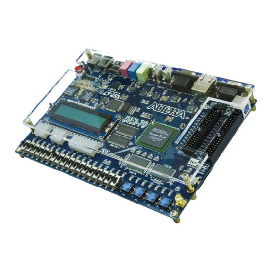
DE2-70 User Manual Chapter 2 Altera DE2-70 Board This chapter presents the features and design characteristics of the DE2-70 board. 2.1 Layout and Components A photograph of the DE2-70 board is shown in Figure 2.1. It depicts the layout of the board and indicates the location of the connectors and key components. -
Page 9: Block Diagram Of The De2-70 Board
DE2-70 User Manual (AS) programming modes are supported 2-Mbyte SSRAM Two 32-Mbyte SDRAM 8-Mbyte Flash memory SD Card socket 4 pushbutton switches 18 toggle switches 18 red user LEDs 9 green user LEDs ... - Page 10 DE2-70 User Manual Figure 2.2. Block diagram of the DE2-70 board. Following is more detailed information about the blocks in Figure 2.2: Cyclone II 2C70 FPGA 68,416 LEs 250 M4K RAM blocks 1,152,000 total RAM bits 150 embedded multipliers ...
- Page 11 DE2-70 User Manual SSRAM 2-Mbyte standard synchronous SRAM Organized as 512K x 36 bits Accessible as memory for the Nios II processor and by the DE2-70 Control Panel SDRAM Two 32-Mbyte Single Data Rate Synchronous Dynamic RAM memory chips ...
- Page 12 Two USB ports (one type A for a host and one type B for a device) Provides a high-speed parallel interface to most available processors; supports Nios II with a Terasic driver Supports Programmed I/O (PIO) and Direct Memory Access (DMA)
-
Page 13: Power-Up The De2-70 Board
DE2-70 User Manual Serial ports One RS-232 port One PS/2 port DB-9 serial connector for the RS-232 port PS/2 connector for connecting a PS2 mouse or keyboard to the DE2-70 board IrDA transceiver Contains a 115.2-kb/s infrared transceiver ... - Page 14 All user LEDs are flashing All 7-segment displays are cycling through the numbers 0 to F The LCD display shows Welcome to the Altera DE2-70 The VGA monitor displays the image shown in Figure 2.3. Set the toggle switch SW17 to the DOWN position; you should hear a 1-kHz sound ...
-
Page 15: Chapter 3 De2-70 Control Panel
DE2-70 User Manual Chapter 3 DE2-70 Control Panel The DE2-70 board comes with a Control Panel facility that allows users to access various components on the board from a host computer. The host computer communicates with the board through an USB connection. The facility can be used to verify the functionality of components on the board or be used as a debug tool while developing RTL code. - Page 16 DE2-70 User Manual close that port; you cannot use Quartus II to download a configuration file into the FPGA until you close the USB port. 7. The Control Panel is now ready for use; experiment by setting the value of some LEDs display and observing the result on the DE2-70 board.
-
Page 17: Controlling The Leds, 7-Segment Displays And Lcd Display
DE2-70 User Manual 7 -SEG Displa y 1 6 x 2 SDRAM Fla sh SSRAM U SB Bla st e r Cont rol PS/2 Code s U SB De vic e SD Ca rd Sok e t LEDs LEDs Figure 3.2. The DE2-70 Control Panel concept. The DE2-70 Control Panel can be used to light up LEDs, change the values displayed on 7-segment and LCD displays, monitor buttons/switches status, read/write the SDRAM, SSRAM and Flash Memory, monitor the status of an USB mouse, read data from a PS/2 keyboard, and read SD-CARD... - Page 18 DE2-70 User Manual Figure 3.3. Controlling LEDs. Choosing the 7-SEG tab leads to the window in Figure 3.4. In the tab sheet, directly use the Up-Down control and Dot Check box to specified desired patterns, the 7-SEG patterns on the board will be updated immediately.
-
Page 19: Switches And Buttons
DE2-70 User Manual Choosing the LCD tab leads to the window in Figure 3.5. Text can be written to the LCD display by typing it in the LCD box and pressing the Set button. Figure 3.5. Controlling LEDs and the LCD display. The ability to set arbitrary values into simple display devices is not needed in typical design activities. -
Page 20: Sdram/Ssram/Flash Controller And Programmer
DE2-70 User Manual Figure 3.6. Monitoring switches and buttons. The ability to check the status of button and switch is not needed in typical design activities. However, it provides users a simple mechanism for verifying if the buttons and switches are functioning correctly. - Page 21 DE2-70 User Manual Figure 3.7. Accessing the SDRAM-U1. A 16-bit word can be written into the SDRAM by entering the address of the desired location, specifying the data to be written, and pressing the Write button. Contents of the location can be read by pressing the Read button.
-
Page 22: Usb Monitoring
DE2-70 User Manual into the memory. The Sequential Read function is used to read the contents of the SDRAM-U1 and place them into a file as follows: 1. Specify the starting address in the Address box. 2. Specify the number of bytes to be copied into the file in the Length box. If the entire contents of the SDRAM-U1 are to be copied (which involves all 32 Mbytes), then place a checkmark in the Entire Memory box. -
Page 23: Ps2 Device
DE2-70 User Manual Figure 3.8. USB Mouse Monitoring Tool. 3.6 PS2 Device The Control Panel provides users a tool to receive the inputs from a PS2 keyboard in real time. The received scan-codes are translated to ASCII code and displayed in the control window. Only visible ASCII codes are displayed. -
Page 24: Sd Card
DE2-70 User Manual Figure 3.9. Reading the PS2 Keyboard. 3.7 SD CARD The function is designed to read the identification and specification of the SD card. The 1-bit SD MODE is used to access the SD card. This function can be used to verify the functionality of SD-CARD Interface. -
Page 25: Audio Playing And Recording
DE2-70 User Manual Figure 3.10. Reading the SD card Identification and Specification. 3.8 Audio Playing and Recording This interesting audio tool is designed to control the audio chip on the DE2-70 board for audio playing and recording. It can play audio stored in a given WAVE file, record audio, and save the audio signal as a wave file. - Page 26 DE2-70 User Manual Figure 3.11. Playing audio from a selected wave file To record sound using a microphone, please follow the steps below: 1. Plug a microphone to the MIC port on the board. 2. Select the “Record MIC” item in the com-box and select desired sampling rate, as shown in Figure 3.12.
Need help?
Do you have a question about the Altera DE2-70 and is the answer not in the manual?
Questions and answers