Table of Contents

Related Manuals for Flight Model Monsun-60


Summary of Contents for Flight Model Monsun-60
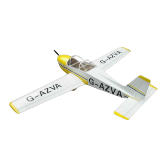
- Page 1 Caution:this plane is not a toy! Before use ,please carefully read this manual. Wing Span:70.8in/1800mm;Flying Weight:3200-3300g; Wing Area:48sq.dm; Radio:4channels 5servos; Length:53.6in/1363mm; Engine:2Cycle-60 or 4Cycle-91;...
-
Page 2: Kit Contents
KIT CONTENTS AILERON SERVO INSTALLATION Cut away covering film for the servo. - Page 3 Attach the two wood to the plywood which are provided by the Fctory. Glue the servo to prepared servo plywood,then put the servo into the servo hole. Ensure plywood is in the right position.
- Page 4 Pull out the servo extention from main wing. Fixup the servo by the screws, then adjust the horn and servo arm. The finished picture as shown.
-
Page 5: Main Wing Installation
MAIN WING INSTALLATION Find out the horns in each sides of the fuselage, then cut the film. Insert the joiner into the fuselage,and find the left and right main wing in the right position. Fasten the wings by the screws provided. Pull the servo extentions into the fuselage from the main wing. -
Page 6: Elevator & Rudder Servo Installation
ELEVATOR & RUDDER SERVO INSTALLATION Find and cut the hole for vertical fin. Insert the vertical fin and glue the decoration wood. Find and cut the hole for stabilizer. - Page 7 Measure and find the centre position of the stabilizer. Cut off the film to make sure securetly glue for stabilizer. Cut off the film for rudder servo assembly.
- Page 8 Cut off the film for elevator servo assembly. Cut away the film along the edges. Glow the stabilizer to the fuselage.
- Page 9 ADJUSTMENT Cut the hole for rudder servo pushrod .
- Page 10 Rudder servo pushrod as shown. Assemble the rudder control horn. Cut the hole for elevator servo pushrod . Elevator servo pushrod as shown.
- Page 11 Assemble the elevator control horn. Install front turning wheel and rudder servos. WHEELS INSTALLATION Install front wheel steering arm in right position.
- Page 12 Assemble front wheel as shown. Fixup the wheel with a hexagonal screw. Insert the landing gear wire into the hole of steering arms,then screw it.
- Page 13 Screw the wheel to the landing gear. Be assured that the screw is fixed up. Install the wheel cover, and fix it up to landing gear with TP screw. Fixup the landing gear strut to fuselage with 3 bolts.
-
Page 14: Engine Installation
ENGINE INSTALLATION ASP 2Cycle 60 size engine as shown. ASP 4Cycle 91 size engine as shown. Line up the template with the firewall thrust lines and mark the location of the engine mounting holes. Use a 1/4 drill to dill the engine mounting holes. -
Page 15: Fuel Tank Installation
If use 4cycle 91 size. Use the same method to this size engine. If use 2cycle 60 size. Install the engine mount on both sides with four 3mm screws. FUEL TANK INSTALLATION Install the fuel tank into the fuselage, and fixup it with belt. -
Page 16: Cowl Installation
Fuel tank detail assembly picture as shown. Install the elevator and rudder servo and throttle into fuselage as shown. COWL INSTALLATION Install the cowling with four TP screws. -
Page 17: Canopy Installation
CANOPY INSTALLATION Assemble the canopy . Make sure it is securitly CONTROL THROWS & CG POSITION... - Page 18 Finished photo...
Need help?
Do you have a question about the Monsun-60 and is the answer not in the manual?
Questions and answers