Advertisement
Quick Links
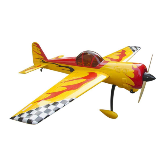
Wing Span:86.6in/2200mm;
Wing Area:94sq.dm;
Length:85.5in/2172mm;
CAUTION : this plane is not a toy!
Before use , please carefully read this manual.
●First-time builders should seek advice from people having building
experience in order to assemble the model correctly and to produce its
performance to full extent .
●Assemble this kit only in places out of children's reach!
●Take enough safety percautions prior to operating this model.
You are responsible for this model's assembly and safe operation!
●Always keep this instruction manual ready at hand for quick
reference,even after completing the assembly.
Flying Weight:7300-7700g;
Radio:6Channel 6Servos;
Engine:50CC Gas
Page1
Advertisement

Related Manuals for Flight Model YAK-55 50CC


Summary of Contents for Flight Model YAK-55 50CC
- Page 1 Wing Span:86.6in/2200mm; Flying Weight:7300-7700g; Wing Area:94sq.dm; Radio:6Channel 6Servos; Length:85.5in/2172mm; Engine:50CC Gas CAUTION : this plane is not a toy! Before use , please carefully read this manual. ●First-time builders should seek advice from people having building experience in order to assemble the model correctly and to produce its performance to full extent .
- Page 2 RUDDER AND TAIL WHEEL ●Make sure to apply Vaseline to the rudder hinges to prevent the epoxy from getting in to the joint. ●Make sure to allow room for epoxy to penetrate the hinges. Carefully slide the rudder onto each hinge and against the trailing edge of the fin.Wipe away excess epoxy with alcohol wetted wipes.
-
Page 3: Stabilizer And Elevator
●Ensure the servo doesn't bind at center or at either end point. Drill holes in the hardwood tail wheel mount and install the blind nut through the opening in the rear of the fuse. Install the mounting screw for the tail wheel. - Page 4 Mount the elevator servo in place and pull the servo wire extension up toward the front. Attach the servo extension wire using foam wire holding brackes or zip ties to the formers along the sides of the fuse so they can't interfere with the rudder control cables.
-
Page 5: Main Wings
Bolt on tabs for Install the servo arm to the servo stabs after making sure the elevator is level with the stab with the servo is in dead center.Tape the elevator in place using blue painter's masking tape. MAIN WINGS Install the aileron horns in place with AB glue.Align the holes in the horns .Install the servo after... -
Page 6: Main Landing Gear
Find out the holes in each sides of fuselage,then remove the covering.Insert the carbon joiner in place,then put on wings. ●Check to make sure you have the carbon in a right length in the wings. Plastic bolt Mounting the wings with plastic bolts on both sides. - Page 7 Permanently tighten the axle to the gear strut by wrenches. Install wheel pants with two mounting bolts. Wheel pants take a lot of abuse, mount securely! The finished photo as shown. Page7...
- Page 8 ENGINE Measure the length of the engine from the firewall mounts to the prop thrust washer for the proper distance allowing 1/4" to 1/2" from the dege of the cowl. Move if needed. Draw the engine ecnter line and thrust line darker with a ball point. Note the 2 degree right thrust built in to the firewall.
-
Page 9: Fuel Tank
Install the canister muffler in the cooling tunnel with a commercial muffler mount and a support in the front of the muffler made of plywood using some silicon tubing for insulation form the heat using glue. FUEL TANK Velcro tank Install the fuel tank mounting straps over foam. - Page 10 Install the battery,receiver and switch in place as shown. CANOPY Slide the rubber backed washers on the hatch mounting bolts and insert bolts through the hatch mounting holes and into the fuse blind nuts.Tighten snugly but do not over tighten and crush the hatch or the fuse sides.
- Page 11 COWLING Mount the cowl using the cowl mounting screws and rubber backed washers.the rubber backed washers are to prevent the fiberglass cowl from cracking from normal engine vibration. CG POSITION & CONTROL THROWS Page11...
- Page 12 Another scheme for choice. Flight Model MFG CO ADD:No.10,Fu Ning Street,Xian Xi Industrial,Chang An Town,Dong Guan City,Guang Dong Province,China Tel: +86-769-85070618 / +86-769-81627996 / +86-769-89790965 Fax: +86-769-85091868 E-mail:info@flight-model.com / flight_model@126.com Web: http://www.flight-model.com/product/eindex.asp http://flight-model.preview.alibaba.com/ Page12...
Need help?
Do you have a question about the YAK-55 50CC and is the answer not in the manual?
Questions and answers