Advertisement
Quick Links
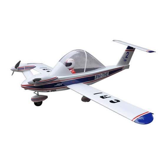
Wing Span:70in/1778mm; Flying Weight:3000g;
Wing Area:39.3sq.dm;
Length:55.1in/1400mm;
CAUTION : this plane is not a toy!
Before use , please carefully read this manual.
●First-time builders should seek advice from people having building
experience in order to assemble the model correctly and to produce its
performance to full extent .
●Assemble this kit only in places out of children's reach!
●Take enough safety percautions prior to operating this model.
You are responsible for this model's assembly and safe operation!
●Always keep this instruction manual ready at hand for quick
reference,even after completing the assembly.
Radio:6Channels 4Servos;
Outer Runner Brushless Motor:BL2819
P1
Advertisement

Related Manuals for Flight Model CRICRI 70


Summary of Contents for Flight Model CRICRI 70
- Page 1 Wing Span:70in/1778mm; Flying Weight:3000g; Wing Area:39.3sq.dm; Radio:6Channels 4Servos; Length:55.1in/1400mm; Outer Runner Brushless Motor:BL2819 CAUTION : this plane is not a toy! Before use , please carefully read this manual. ●First-time builders should seek advice from people having building experience in order to assemble the model correctly and to produce its performance to full extent .
-
Page 2: Main Wings
MAIN WINGS Gather the mian wing,aileron and hinges. Attach the aileron to the main wing with AB glue. Cut away covering film for the servo in the bottom of the wing. Install the servo to the servo hole. -
Page 3: Install The Canopy
Put the servo in the right position,then fixup it,and Assemble aileron、servo arm and pushrod. Insert the main wings with joiner,then screw them by nylon screws. Install the Canopy Put the Canopy into the right position on the top of the fuselage. - Page 4 Stabliazer Use 4 Screws fixed the stablizer each side as the photo shown. RUDDER AND ELEVATOR Install a servos ectention onto the elevator servo.Either tie the srco leads together,or use a connector to secure the extension to prevent it from coming loose during flight. Another way...
- Page 5 THE MOTOR INSTALLED Istall the front steering landing gear into fuselage as photo shown.then put the ALU landing gear into as photo shown fixed by four 3mm screws. The steering connecting rod two sides was connected by two regulators,one put in the servo arm,and another one put in steering arm,between the regulators there has one 1.5mm steel wire.
- Page 6 Install the ESC as the photo shown. Pls be attention that need cut a hole on the cowl in order to let the ESC wires be outside. Use two screw fixed the Alu squares cap in the alu squares,then put the motor cabinet fixed by M3 screw.other side install locknut.
- Page 7 Install the motor by M3 screws. then let the motor line with ESC line connected together. Install the Motor Cover First install the second part as the photo shown. then install the front part as shown.
-
Page 8: Throttle Servo
In the middle part fixed by tapping screw. THROTTLE SERVO Assemble the receiver and receiver battery as shown. - Page 9 UNDERCARRIAGE Install the undercarriage to the bottom of the fuselage. Permanently tighten the axle to the gear strut by wrenches. CG POSITION & CONTROL THROWS...
- Page 10 FINISHED PHOTO Flight Model CO.,LTD ADD:No.10,Fu Ning Street,Xian Xi Industrial,Chang An Town,Dong Guan City,Guang Dong Province,China...
- Page 11 Tel: +86-769-85070618 / +86-769-81627996 / +86-769-89790965 Fax: +86-769-85091868 E-mail:info@flight-model.com / lorna@flight-model.com Web: http://www.flight-model.com/product/eindex.asp http://flight-model.preview.alibaba.com/...
Need help?
Do you have a question about the CRICRI 70 and is the answer not in the manual?
Questions and answers