Table of Contents
Advertisement
Quick Links
Advertisement
Table of Contents

Subscribe to Our Youtube Channel
Related Manuals for CAE Apollo


Summary of Contents for CAE Apollo
- Page 1 CAEApollo User Guide Your worldwide training partner of choice...
-
Page 2: Table Of Contents
Standard Equipment and Accessories ......... . .15 ©2020 CAE 905K351052 v1.1... -
Page 3: Contents
Apollo Replacement Lithium Battery ........ - Page 4 Breakdown ..............69 ©2020 CAE 905K351052 v1.1...
- Page 5 RF Channel Initial Operating Frequencies ........91 ©2020 CAE 905K351052 v1.1...
-
Page 6: Cautions And Warnings
• Do not attempt to disassemble the simulator or service any of the electrical components without receiving instructions from Customer Service. • Do not operate the manikin in rain. Apply water to the manikin only in accordance with the supported clinical procedures explained in this guide. ©2020 CAE 905K351052 v1.1... -
Page 7: Product Use Warnings
Fluids System For manikins such as Apollo that are equipped with fluid systems: • Do not modify the reservoirs or any assembly component. • Always protect your eyes, skin, and clothing against accidental exposure. -
Page 8: Important Canister Information
• Do not expose the CO 2 canister to heat above 140° F, as rupture may occur. • Never point the CO 2 canister towards your face or someone nearby. • Use only CAE specified CO 2 canisters. Regulator Assembly •... -
Page 9: Use Of Equipment
• Batteries can be charged and used between 32°F (0°C) and 113°F (45°C)Do not charge the battery while it is inside the simulator. • Do not use or charge the battery inside of a car where temperatures may exceed 176˚F (80˚C). ©2020 CAE 905K351052 v1.1... -
Page 10: Battery Safety Information
• Avoid excessive physical shock or vibration. • Keep out of the reach of children. • For rechargeable batteries, the battery must be charged in an approved charger. • Never use a modified or damaged charger. ©2020 CAE 905K351052 v1.1... -
Page 11: Potential Health Effects
Should exposure to hazardous battery components occur, or in the event of a fire, follow all local first aid measures and safety protocols. Transport Information CAE complies with the most current International Air Transport Association (IATA) Dangerous Goods Regulations when transporting and shipping Li-ion batteries. The following terms are defined as follows: Consignment - Equivalent to the term "shipment,”... - Page 12 Shipping regulations and requirements may vary depending upon: • Wattage of the battery. • Whether the battery is shipped independent of, contained within, or packed with the equipment. When transporting batteries CAE follows these documentation and labeling requirements: Item Description Batteries Shipped Independent of...
- Page 13 CAEApollo Cautions and Warnings Batteries contained in or packed with the MSI TouchPro UN No. 3091 UN Shipping Name: Lithium Metal Batteries Transport Hazard Class: Labeling: ©2020 CAE 905K351052 v1.1...
-
Page 14: Specifications
Laptop 50°F to 95°F -13°F to 113°F 0% to 90% (10°C to 35°C) (-24°C to 45°C) non-condensing Maximum Altitude Item Operation Storage Shipping Laptop 10,000 ft (3,048 m) 15,000 ft (4,572 m) 35,000 ft (10,668 m) ©2020 CAE 905K351052 v1.1... -
Page 15: Battery
• Wired: 10/100 Ethernet • Wireless: IEEE 802.11 g • Wireless Voice • 537 MHz to 819MHz (Country Specific) Electrotherapy Item Description Defibrillation • 20 to 360 Joules (Monophasic, Biphasic) Pacing • 20 mA to 180 mA ©2020 CAE 905K351052 v1.1... -
Page 16: Air Supply
To properly regulate psi, the optional wall air kit must be used in conjunction with the facility supply source and facility wall adapter. The wall air kit is an additional optional accessory. When using a CAE External Air kit in conjunction with a supply source at a facility, it is recommended that the facility air supply be 30-psi to 60-psi (2-bar to 4-bar). - Page 17 CAEApollo Specifications THIS PAGE INTENTIONALLY LEFT BLANK ©2020 CAE 905K351052 v1.1...
-
Page 18: System Requirements
100BASE-T Ethernet Adapter Mac is a registered trademark of Apple Inc. Windows and Internet Explorer are registered trademarks of the Microsoft Corporation in the United States and/or other countries. Chrome is a registered trademark of Google Inc. ©2020 CAE 905K351052 v1.1... -
Page 19: Approved Devices
Note: Upon installation, the software takes up 1.2 GB of hard drive. For standalone versions of Maestro, the software can store approximately 30.8 GB of patient record files. In the event this storage capacity is expected to be maximized, plan for additional hard drive space. ©2020 CAE 905K351052 v1.1... -
Page 20: Equipment Overview
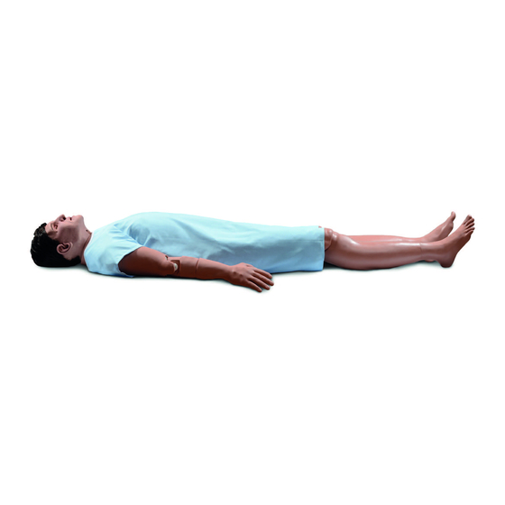
At six feet, two inches (188 cm) in height and weighing 100 pounds (45.36 kg), Apollo is fully operational in the supine, lateral, prone and seated positions. The simulator offers features like arm pronation and supination; breath, heart and bowel sounds; palpable pulses;... -
Page 21: Co2 Canisters (Prehospital Only)
Equipment Overview CO2 Canisters (Prehospital Only) Four CO2 canisters are included with Apollo to supply the on-board CO2 exhalation feature. Power Adapter and Cord The simulator comes with a power adapter and cord; no other power cord should be used with Apollo. -
Page 22: Trauma Fill Tank
FX Simulated Wound Kit enable instructors to create real-life scenarios at authentic locations. Optional Equipment Patient Monitor Mircosoft Surface Go Tablet Apollo Replacement Lithium Battery External Compressed Air Kit External CO2 Kit Air Compressor Hands-Free Training Cables... -
Page 23: Patient Monitor
External CO2 Kit The External CO2 Kit gives the user the ability to connect Apollo to an external source of CO2 (30-120 psi). The External CO2 Kit includes a flexible 30 ft (9 m) hose attached to a preset air regulator and an adapter for wall or tank fittings. -
Page 24: Tool Kit
Optional components include amputations, degloving of the hand, and impalement. Moulage Kit The kit provides the materials needed to create wounds on Apollo. The Moulage Kit may also be ordered separately. ©2020 CAE 905K351052 v1.1... - Page 25 CAEApollo Equipment Overview THIS PAGE INTENTIONALLY LEFT BLANK ©2020 CAE 905K351052 v1.1...
-
Page 26: Meet Apollo
In addition, Apollo has the assessment, cardiovascular, genitourinary, and trauma features familiar to CAE customers plus an SpO finger probe, fluids on board, bilateral noninvasive blood pressure, and IV access. - Page 27 CAEApollo THIS PAGE INTENTIONALLY LEFT BLANK ©2020 CAE 905K351052 v1.1...
-
Page 28: Setup
• Plug in the tablet, manikin, and rechargeable accessories to a power source using only the power cords provided. Use the diagram provided in the Unpacking Your CAE Manikin to identify the designated cords associated with this equipment. -
Page 29: Setup Procedure
Failure to wrap the manikin in a sheet may result in permanent damage to the manikin skin. CAE is not responsible for damage to the manikin skin if the manikin is not wrapped in a sheet while using the stretcher. -
Page 30: Step 2: Attach Lower Legs To The Manikin
Removing the Locking Pin b. Place lower limbs in their correct positions, leaving enough room to manipulate connectors. c. On each leg, match and connect the color-coded tubing to the three white tubing connectors. Connecting Tubing ©2021 CAE 905K351052 v1.1... - Page 31 Carefully place tubes and cables in the hole on the lower leg. f. Align holes on the knees and insert the locking pin. g. Screw the nut on the locking pin, holding it in place. Affixing the Locking Pin ©2021 CAE 905K351052 v1.1...
-
Page 32: Step 3: Power On The Manikin
Power on the laptop. Step 5: Connect to the Simulator’s Network Once Apollo simulator and the Instructor laptop are both powered on, they automatically establish a wireless connection and, when the Internet Explorer browser is opened, the Maestro software launches. -
Page 33: Step 6: Launch Maestro
From the desktop screen, tap the Maestro app. The CAE Maestro Desktop Icon The Maestro start page appears. b. Tap the CAE Maestro icon. The CAEMaestro Icon The Maestro application starts and is ready to be used with the simulator. It will connect to the simulator automatically in the future. - Page 34 Hardwired Connection No WiFi If the No WiFi icon appears: a. Tap the Network icon. The Network window appears. The WiFi button The Network Window b. Tap WiFi button to turn on WiFi (button turns blue). ©2021 CAE 905K351052 v1.1...
- Page 35 From the desktop screen, tap the Maestro app. The Maestro start page appears. b. Tap the CAE TouchPro icon. The TouchPro application starts and the TouchPro Workstation is ready to be used with the simulator. It will connect to the simulator automatically in the future.
-
Page 36: Optional Step: Connect To The Spo2
Optional Step: Connect External Air Using the External Air kit allows Apollo to be run by an external air source rather than the internal compressor. The air hose can be connected to or disconnected from Apollo at any time. When the external air pressure is sensed, the pump internal to Apollo turns off automatically. -
Page 37: Optional Step: Detach The Arms
• Discontinue use of this equipment if leakage or visible damage is evident. Optional Step: Detach the Arms Apollo’s arms may be removed for use with trauma scenarios. To detach Apollo’s arms: a. Unscrew and remove the locking pin at the elbow. -
Page 38: Optional Step: Prepare The Bleeding System
The trauma fill tank is used to fill the on-board blood reservoir. Step a: Attach the Overflow Bottle to the Trauma Fill Tank Assembly The overflow bottle is used to collect overflow when the Apollo on-board tank is filled. To attach the overflow bottle to the trauma fill tank: 1. - Page 39 3. Lock the pump handle back into the pump assembly by turning clockwise. 4. Watch the Overflow Bottle located on the tank assembly. When liquid begins to appear in this bottle, the on-board blood reservoir is full. Filling the on-board blood reservoir takes approximately 3 to 5 minutes. ©2021 CAE 905K351052 v1.1...
- Page 40 Step f: Disconnect the Trauma Fill Tank Umbilical from the Simulator Disconnect the trauma fill tank umbilical from the simulator and store the assembly out of the way for later use. After use, ALWAYS release pressure and clean the tank. ©2021 CAE 905K351052 v1.1...
- Page 41 CAEApollo Setup THIS PAGE INTENTIONALLY LEFT BLANK ©2021 CAE 905K351052 v1.1...
-
Page 42: Using Apollo
Using Apollo SING POLLO Once the simulator is assembled, the Apollo manikin is ready for learners to practice and master new competencies, interventions, and skills during clinical scenarios. To create a fully immersive simulation experience with advanced intervention capabilities and realtime data feedback, the Apollo simulator utilizes instructor-led software with scenario programming capabilities. -
Page 43: Head Secretions (Prehospital Only)
To use the head secretion features: 1. Using a 50 ml syringe, prime the line of the desired secretion by injecting fluid into the NOSE, MOUTH or EYES port on Apollo’s left shoulder until fluid emerges from the secretion sites. - Page 44 The NOSE, MOUTH and EYES ports Apollo Prehospital’s Left Shoulder 7. Open the clamp and allow fluid to flow into the simulator. 8. Keep the IV bag attached. Adjust the flow rate manually using the roller clamp. Note: Cleanup is very important when using simulated fluids. For more information about cleaning the fluid out of the manikin, see the Care and Maintenance section of this guide.
-
Page 45: Respiratory System
Apollo Prehospital’s Respiratory system is comprised of the airway management, spontaneous breathing and ventilation features. On Apollo Nursing, various clinical signs such as breath sounds, chest excursion and airway patency can be physically demonstrated. A series of speakers inside each simulator can generate a range of breath and throat sounds used in diagnosing conditions. - Page 46 Patient Status Display can be configured to show them. Venous Blood and PvCO are continuously None required, but None required. Gases adjustable. calculated, and the Patient Status Display can be configured to show them. ©2020 CAE 905K351052 v1.1...
- Page 47 Respiratory and Airway larynx and prevents intubation, but adjust Airway Occlusion Occlusion toggle. allows mask ventilation of the patient’s lungs, thereby creating a VIEW: Respiratory “cannot intubate, can ventilate” scenario. CONTROL: ON/OFF ©2020 CAE 905K351052 v1.1...
-
Page 48: Chest Excursion
• Intrapleural Volume: Disables chest excursion on the affected side but still allows for excursion on the unaffected side. Needle Decompression (Prehospital Only) Needle decompression can be performed bilaterally into a small hole located in the midclavicular line of the second intercostal space. ©2020 CAE 905K351052 v1.1... - Page 49 Chest Tube Both Apollo Prehospital and Nursing has the ability to simulate chest tube drainage. The Chest Tube sites are located bilaterally in the fifth intercostal space. Ensure all fluids have been removed from previous uses before each new use to prevent overfilling.
- Page 50 Chest Tube ports Apollo’s Right Shoulder 7. Open the clamp and allow fluid to flow into the simulator until fluid is seen in the Apollo Priming Tube. 8. Once fluid appears in the Apollo Priming Tube, remove the Apollo Priming Tube. The simulator is ready for chest tube insertion.
- Page 51 When the Chest Tube feature is used on Apollo Prehospital, the simulator automatically detects the tube insertion and creates a log entry. On Apollo Prehospital, if a small volume of fluid is needed to simulate proper chest tube insertion, the internal reservoir may be filled.
- Page 52 Intubation The upper airway of the Apollo manikin is designed to allow for intubation and laryngoscopy. Direct laryngoscopy as well as oral and nasal tracheal intubation can be performed using devices such as endotracheal tubes, nasopharyngeal airways, and oropharyngeal airways.
-
Page 53: Cricothyrotomy
2. Remove the tracheal plug. 3. Prime the airway reservoir using silicone oil spray. 4. Place the tracheostomy tube into the tracheostomy site and secure it in place. 5. After the simulation, remove the tracheostomy tube and replace the plug. ©2020 CAE 905K351052 v1.1... - Page 54 Using Apollo Airway Secretions (Nursing Only) Apollo Nursing allows for suctioning of fluids from the airway using a manual feed. Ensure all fluids have been removed from previous uses before each new use to prevent overfilling. Tracheostomy Suction To use the airway secretion feature: 1.
-
Page 55: Cardiovascular System
Care and Maintenance of this user guide. Cardiovascular System The Apollo manikin includes cardiovascular features that allow learners to practice basic assessment and life support skill sets. With the Apollo manikin, learners can: • Palpate pulses •... - Page 56 Blood Pressure measured using the return-to-flow Korotkoff sounds blood pressure Measurement technique. can be adjusted cuff with T- by tapping adapter. Connect Sounds on the T-adapter to NIBP Run screen and connection. then the Korotkoff tab. ©2020 CAE 905K351052 v1.1...
-
Page 57: Pulses
Carotid pulses are also controlled together. Pulses are controlled (enabled, disabled, and deficits) from the Maestro software. All pulses, unless altered by an SCE, are enabled by default. For more information, see the Maestro for Apollo User Guide. IV Cannulation Veins for the IV Cannulation feature are located in the dorsum of the hands, forearms and antecubital fossa region of the arms. - Page 58 To prime the IV access ports, connect a 50 ml syringe filled with distilled water (with clinically appropriate food coloring if desired) to the IV FILL port on Apollo’s right shoulder and firmly inject all 50 ml. This primes the arm and charges the system for Flashback and Venipuncture support.
-
Page 59: Iv Administration
Intraosseous (IO) Cannulation and Administration Apollo also allows for humeral intraosseous (IO) cannulation and administration. The designated IO site are located on Apollo’s left shoulder and right tibia (optional). Use a 25 mm needle only with IO cannulation. No more than 1 ml of fluid should be flushed per cannulation. Ensure all liquid is removed from previous use. -
Page 60: Subclavian Catheter (Nursing Only)
To decrease the likelihood of staining, apply a thin coat of petroleum to the area of bleeding. To use one of the moulage wounds from the Moulage Kit: 1. Secure the wound over the simulator using the integrated straps. ©2020 CAE 905K351052 v1.1... - Page 61 For more information setting up fluids on the manikin using the trauma fill tank, see the Setup section of this user guide. For cleaning after using fluids, see Care and Maintenance section of the user guide. For more information on how to operate the software, see the Maestro for Apollo User Guide. Hemorrhage Control When bleeding is controlled (e.g., hemostat, tourniquet), the action is detected and logged, and the...
-
Page 62: Chest Compressions
Apollo can detect the compressions, and the physiology responds accordingly. On Apollo, a 5-lead ECG is emitted from the appropriate positions for display on a standard monitor. To produce ECG signals on a monitor, connect the lead unit to the ECG contacts (or snaps) located on the manikin. -
Page 63: Defibrillation, Cardioversion, And Pacing
The manikin can receive simulated electrical therapy by administering defibrillation through the software or by using the SymDefib device with a live defibrillator. Simulated Defibrillation For instructions on administering defibrillation through the software, refer to the Maestro for Apollo User Guide. Commercial Defibrillation The manikin is designed to safely absorb the energy discharged from commercial defibrillators. - Page 64 Coarse ventricular fibrillation and high-rate ventricular tachycardia cardiac rhythms are automatically recognized as “shockable” rhythms. • With each defibrillation, Apollo automatically records the amount of energy discharged and the time defibrillation was performed. The simulated patient response to defibrillation is determined by the scenario script or instructor intervention. Thus, cardioversion is not automatically determined by the physiological models.
- Page 65 A standard transthoracic cardiac pacemaker can be connected to the simulator using the anterior contacts. The simulator automatically detects and responds to pacing signals (from 20 mA to 200 mA, in increments of 10). For more information, see the Maestro for Apollo User Guide. ©2020 CAE 905K351052 v1.1...
-
Page 66: Blood Pressure
Using Apollo Blood Pressure Apollo supports non-invasive blood pressure measurements, and systolic and diastolic readings can be obtained and manipulated through the software. Systolic and Diastolic Blood Pressure To manually adjust the systolic and/or diastolic blood pressure: 1. From the Cardiovascular panel, select the parameter of desired blood pressure. - Page 67 CAEApollo Using Apollo 1. Connect the extension from the T-fitting on the blood pressure cuff adapter to either of the NIBP ports on Apollo’s left andright side shoulders. NIBP LEFT port Apollo Prehospital’s Left Shoulder NIBP LEFT port Apollo Nursing’s Left Shoulder NIBP RIGHT port Apollo’s Right Shoulder...
-
Page 68: Gastrointestinal System
At appropriate cuff pressures, the radial pulse disappears and Korotkoff sounds are produced. Gastrointestinal System Apollo produces realistic bowel sounds. Auscultation of normal and abnormal bowel sounds can be performed with a stethoscope. In addition, on Apollo Nursing, gastric lavage and gavage can be administered. Gastric Gavage and Lavage (Nursing Only) Apollo Nursing has a gastric reservoir that allows for simulated nasogastric gavage and lavage. -
Page 69: Genitourinary System
CAEApollo Using Apollo Genitourinary System Apollo may beconfigured with either male or either of which allows for the insertion of a urinary catheter.The genitourinary system also provides for the excretion of urine. Changing the Simulator’s Genitalia Apollo comes with male and female genitalia. - Page 70 5. Connect to the simulator by attaching the end of the IV spike set tubing to the GU port on the simulator’s left shoulder. The GU port Apollo Prehosptial’s Left Shoulder The GU port Apollo Nursing’s Left Shoulder 6. Open the clamp and allow fluid to flow into the simulator. There is a reservoir inside the simulator that fills up with the fluid.
-
Page 71: Medication Administration
Medication Administration Simulated Medication Certain medication administration can be simulated using the instructor software. For more information on administering medication in the software only, see the Maestro for Apollo User Guide. Intravenous, Intramuscular/Subcutaneous, and Intraosseous Medication Learners can administer medications via IM/SQ injection, IV cannulation or intraosseous injection. For more information on these medication administration techniques, see the Cardiovascular section of this user guide. -
Page 72: Sounds
A variety of simulated sounds are available to enhance realism. Sounds are controlled through the instructor software and a patient must be running in the software for any sounds to be available. To auscultate sounds on the Apollo manikin, be sure to locate a stethoscope prior to beginning a simulation. -
Page 73: Microphones
Wireless Microphone The wireless microphone volume can be adjusted on the microphone itself using the volume control. For more information, see Appendix B - Wireless Voice Link. THIS PAGE INTENTIONALLY LEFT BLANK ©2020 CAE 905K351052 v1.1... -
Page 74: Care And Maintenance
Following the use of the simulator, make sure all components are properly handled and correctly removed or placed into storage. Note: Do not attempt to open or repair any simulator components with out authorization from CAE Customer Service or their representative. Doing so may void the warranty. Many hardware components within the simulator and Instructor Workstation are not user-serviceable. -
Page 75: Step 1: Clean The Manikin
Gently rub the soiled area with a soft cloth to remove most marks and stains. DO NOT use solvents or abrasive pads. Inspect the manikin for damage or puncture marks. If damage exists, contact CAE Healthcare Customer Service immediately for a repair. Prompt repair prevents expansion of the damaged area. - Page 76 Pour 480 ml (16 oz) of distilled water into the tank and reinstall the Pump Assembly. The Overflow Bottle holds 16 ounces. e. Place the Overflow Bottle lid with umbilical attached into the wastewater bucket. ©2020 CAE 905K351052 v1.1...
- Page 77 Always depressurize the tank, remove trauma fluid and clean the tank before performing maintenance. The pump assembly may need periodic lubrication. Call CAE Customer Service for details if the pump loses the ability to create pressure, squeaks loudly or is difficult to move.
- Page 78 Damaged pump cylinder Contact CAE for service. gasket or o-ring Turn valve until it returns to a “sealed” position. Tank pressure relief valve is set to “open.”...
- Page 79 Using the same syringe, push air through the subclavian catheter until empty. Handling CO Canisters (Prehospital Only) Careful handling is required in the use of CO canisters. Please read and follow all appropriate cautions and warnings. ©2020 CAE 905K351052 v1.1...
-
Page 80: Step 3: Power Off The Instructor Laptop
The tablet desktop screen appears. d. Tap the Start menu icon in the lower-left corner. Start Menu A menu appears. e. From the menu, tap the Power button. A menu appears. f. From the menu, tap Shut down. ©2020 CAE 905K351052 v1.1... -
Page 81: Step 4: Power Off The Manikin
Care and Maintenance Step 4: Power Off the Manikin To power off the manikin, carefully pull back the skin on Apollo’s left hip and hold the power button for two seconds. The light on the button will blink, indicating shutdown is in progress. Allow up to 30 seconds for complete shutdown. - Page 82 Care and Maintenance 3. Remove the abdominal support. Removing the Abdominal Support 4. Release the Velcro battery tie-down. Removing the Battery Tie-Down 5. Disconnect the battery leads. ©2020 CAE 905K351052 v1.1...
-
Page 83: Recharging The Battery
To recharge the battery, disconnect and remove the battery from the simulator and connect to the external charger provided. WARNING: When handling Apollo’s batteries, be sure to adhere to all the cautions and warnings. Recharging should take approximately four hours. -
Page 84: Storage
Important : Do not attempt to open or repair any simulator components. Doing so may void the warranty. If damage exists, contact CAE Customer Service immediately for a repair. Prompt repair prevents expansion of the damaged area. Prior to storing the product: •... -
Page 85: Long-Term Storage
Repack Manual (this document also was included when the simulator was shipped). The shipping container is approximately 2 feet (61cm) by 6 feet (183 cm). Note : Prior to using the manikin, ensure it reaches room temperature. ©2020 CAE 905K351052 v1.1... -
Page 86: Appendix A - Recommended Clinical Supplies
A - R PPENDIX ECOMMENDED LINICAL UPPLIES The following clinical supply sizes are recommended for use with Apollo. Other sizes may cause damage to the simulator and should not be used. Recommended Tube, Needle and Apollo Prehospital Apollo Nursing Airway Sizes... - Page 87 CAEApollo Appendix A - Recommended Clinical Supplies THIS PAGE INTENTIONALLY LEFT BLANK ©2020 CAE 905K351052 v1.1...
-
Page 88: Appendix B - Wireless Voice Link
There are two unique devices that make up a WVL pair: the handset device and the base station device. The base station device is located inside the simulator, while the handset device is battery powered and carried by the user. The handset transmits voice input through a microphone to the ©2020 CAE 905K351052 v1.1... -
Page 89: Physical Features
• Red power light: Indicates when the unit is powered on by blinking. Also indicates when the Mute button is activated by solidly staying on • Green connection light: Indicates an RF link connection between the handset and base station by blinking WVL Front View ©2020 CAE 905K351052 v1.1... -
Page 90: Preparing The Base Station In The Simulator
When using the base station in the simulator, ensure the batteries are removed and the following items are attached: • Power cable • Line out cable The DIP switch is located in the battery compartment of the base station. Dip Switch Settings ©2020 CAE 905K351052 v1.1... -
Page 91: Preparing The Handset For Use
While DIP switch positions 6 through 8 affect the handset and base station settings, DIP switch positions 1 through 5 are used to set the radio frequency channel used for communication between the handset and the base station. ©2020 CAE 905K351052 v1.1... -
Page 92: Selecting The Radio Frequency Channel
Channel Group 2. To give unique initial RF frequencies, assign each WVL pair to its own RF channel with the settings found in CH 12 through CH 31. RF Channel Selection Methods For a complete list of the initial frequencies associated with the RF Channels, see RF Channel Initial Operating Frequencies. ©2020 CAE 905K351052 v1.1... -
Page 93: Powering Up The Wvl Pair
DIP switch position 6 on the handset determines if the iPhone microphone input or the standalone microphone input is enabled. When DIP switch position 6 is set to the OFF position, the standalone microphone jack is enabled for the standalone microphone, provided by CAE. Handset and CAE -provided Microphone To use a microphone compatible with an iPhone (three-pole jack), set DIP switch position 6 to ON. -
Page 94: Special Handset Settings
Troubleshooting CAE Customer Service is available to help with issues, should they arise. However, sometimes you can speed up the customer service process by performing diagnostics before calling and eliminating some problems on your own with the help of the following instructions. -
Page 95: Power Problems
The simulator voice output is cut off when the speaker is speaking quietly. In this case, there are three possible options: Attempt to talk louder. º Increase the microphone gain. º Disable the noise reduction feature by setting the handset DIP switch 8 to OFF. º ©2020 CAE 905K351052 v1.1... -
Page 96: Rf Channel Initial Operating Frequencies
2.406 2.476 2.408 2.474 2.410 2.472 2.412 2.470 2.414 2.468 2.416 2.466 2.418 2.464 2.420 2.462 2.422 2.460 2.424 2.458 2.426 2.456 2.428 2.454 2.430 2.452 2.432 2.450 2.434 2.448 2.436 2.446 2.438 2.444 2.440 2.442 ©2020 CAE 905K351052 v1.1... - Page 97 For more information about CAE products, contact your regional sales manager or the CAE distributor in your country, or visit caehealthcare.com. Tel +1 941-377-5562 or 866-233-6384 For customer service, please contact CAE. Customer Service Headquarters - United States Monday - Friday from 7:00 a.m. to 6:00 p.m. ET Phone 1-866-462-7920 Email: srqcustomerservice@cae.com...
Need help?
Do you have a question about the Apollo and is the answer not in the manual?
Questions and answers