Table of Contents
Advertisement
Quick Links
Advertisement
Table of Contents

Related Manuals for RC Electronics FenixN

Summary of Contents for RC Electronics FenixN
- Page 1 FenixN – user’s manual Revision 1.5.B50 RC Electronics d.o.o. January 2022...
- Page 2 FenixN – user’s manual Document Revision: 1.5.B50 January 2022 Contact Information Publisher and producer: RC Electronics d.o.o. Otemna 1c 3201 Šmartno v Rožni dolini Slovenia Email: support@rc-electronics.eu...
- Page 3 FenixN – user’s manual Document Revision: 1.5.B50 January 2022 Revision History The following table shows full description of changes made in this document. DATE DESCRIPTION January 2022 • Initial release of document.
-
Page 4: Table Of Contents
FenixN – user’s manual Document Revision: 1.5.B50 January 2022 Contents 1 Introduction..............................6 1.1 Reserves all rights..........................7 2 Basic operation............................8 2.1 Powering up............................8 2.2 Front view 80 mm unit........................9 2.3 Front view 57 mm unit........................10 2.4 User interface..........................11 2.4.1 Main unit right push-rotary knob...................11 2.4.2 Main unit left push-rotary knob....................11... - Page 5 FenixN – user’s manual Document Revision: 1.5.B50 January 2022 3.3 Indicator Flarm radar page......................26 3.4 Main unit turn-point navigation page.....................28 3.5 Main unit airport navigation page....................30 3.6 Main unit task navigation page.......................31 3.7 Main unit nearest airport page.......................35 3.8 GPS info page..........................37 3.9 Logbook page..........................38...
- Page 6 FenixN – user’s manual Document Revision: 1.5.B50 January 2022 9.3 During flight............................65 9.3.1 Set QNH..........................65 9.3.2 Wind calculation........................65 9.3.3 Influence of wind in final glide....................66 9.3.4 Event function........................66 9.3.5 Task start..........................66 9.4 After landing...........................66 9.4.1 Downloading flights........................66...
-
Page 7: Introduction
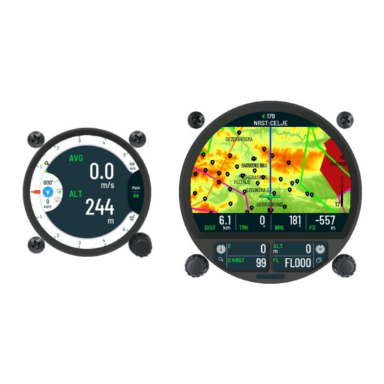
FenixN – user’s manual Document Revision: 1.5.B50 January 2022 1 Introduction The FenixN system is a pair of main 80mm and 57mm indicator unit. It is IGC certified flight recorder system (Level 1) with ENL detection (IGC approval pending). User interaction with the system is done via three rotary knobs. Two rottary knobs are on main 80mm unit and one is on 57mm indicator. -
Page 8: Reserves All Rights
Any use of this document by way of reproduction, modification or third-party use, without the written permission of RC Electronics is prohibited. This document can be only updated or modified by RC Electronics. This document may be revised by RC Electronics at any time. -
Page 9: Basic Operation
2.1 Powering up To turn on the device, press and hold left knob on main unit until the FenixN logo appears on the main screen. Once turned on, the following info screens will appear on main display: ... -
Page 10: Front View 80 Mm Unit
FenixN – user’s manual Document Revision: 1.5.B50 January 2022 2.2 Front view 80 mm unit Reference front view of device. Also the FenixN intro screen. 1 – Main screen 2 – Left push-rotary knob 3 – Additional screen ... -
Page 11: Front View 57 Mm Unit
FenixN – user’s manual Document Revision: 1.5.B50 January 2022 2.3 Front view 57 mm unit Reference front view of indicator. 1 – Main screen 2 – Push-rotary knob ... -
Page 12: User Interface
FenixN – user’s manual Document Revision: 1.5.B50 January 2022 2.4 User interface Rotary knobs are used by the pilot to interact with the system. To get more understanding of their use, we will describe all functions in next sub-sections. Knobs can be turned clockwise CW or counter clockwise CCW. -
Page 13: Software Update
, adding contact details, device spec and current software revision of the FenixN system. In a short time, our staff will provide you with software update file. All required device info can be obtained in Setup / Info page. -
Page 14: System Shutdown
FenixN – user’s manual Document Revision: 1.5.B50 January 2022 2.6 System shutdown 2.6.1 Loss of main input power System will automatically shut down when external voltage is not detected anymore, system is not in flight and there is no human interaction via rotary knobs for last 2 min. -
Page 15: Shutdown During Ongoing Flight Mode
FenixN – user’s manual Document Revision: 1.5.B50 January 2022 2.6.4 Shutdown during ongoing flight mode If the loss of main input power comes during flight mode, the system will keep its normal operation due to internal integrated battery which can provide power to the system. -
Page 16: Indicator Main Page
FenixN – user’s manual Document Revision: 1.5.B50 January 2022 3.1 Indicator main page Main page on indicator displays all needed flight information. It can display up to four digital numeric navbox information on main screen. Together with digital numeric information there is also current wind direction and its speed. -
Page 17: Indicator Digital Numeric Navigation Information
FenixN – user’s manual Document Revision: 1.5.B50 January 2022 3.1.1 Indicator digital numeric navigation information Large view area of the main screen is used to display digital numeric information. The pilot can set up to four digital numeric values at the same time on the main screen. Type of them can be set by user for each flying mode (thermal / glide). -
Page 18: Flight Mode
FenixN – user’s manual Document Revision: 1.5.B50 January 2022 3.1.2 Flight mode Navigation data is separately set for both flight modes. Device will detect the mode of flight and switch view mode of all informational positions on screens. The status icon at bottom right of the vario screen always indicates the current detected flight mode. -
Page 19: Battery Status
FenixN – user’s manual Document Revision: 1.5.B50 January 2022 3.1.5 Battery status Battery status indicator displays internal battery voltage level of the system. Indicator will be displayed in following modes: FLASHING MODE – indicates that the system is currently using internal integrated battery. -
Page 20: Indicator Navbox Subpage
FenixN – user’s manual Document Revision: 1.5.B50 January 2022 3.1.6 Indicator navbox subpage The sub-menu Select navbox is where pilot can set number of navboxes on indicator main screen for each flight mode, type of needle for each flight mode and type of navbox displayed. - Page 21 FenixN – user’s manual Document Revision: 1.5.B50 January 2022 3.1.6.1 Customizing displayed navigational data Information displayed on main screen are specified by Set navbox sub-page. By confirming selection, display will show main page for customization of displayed navigational data. Option for change navigational informational.
- Page 22 FenixN – user’s manual Document Revision: 1.5.B50 January 2022 On Select navbox subpage, pilot can scroll through the navigation list of data. Select navbox page. Selection can be made between the following data. Short press on bottom rotary knob will confirm selection.
-
Page 23: Indicator Main Page Sub-Menu
FenixN – user’s manual Document Revision: 1.5.B50 January 2022 3.1.7 Indicator main page sub-menu To access sub-menu for adjusting Volume, MacCready, Ballast, Bugs, QNH and Brightness press on knob. Volume settings. Volume will be set for current flight mode (Vario / SC). - Page 24 FenixN – user’s manual Document Revision: 1.5.B50 January 2022 Bugs setting. QNH setting. Brightness setting.
-
Page 25: Indicator Thermal Assistant Page
FenixN – user’s manual Document Revision: 1.5.B50 January 2022 3.2 Indicator thermal assistant page While thermalling, all thermal information can be vied on Thermal assistant page. Designed to provide best user interface displaying all essential thermal information to the pilot. The displayed Thermal assistant page will show following information on main screen: GAIN –... - Page 26 FenixN – user’s manual Document Revision: 1.5.B50 January 2022 Colors of the dots, will display following type of the thermal: Red circuit – will indicated positive thermal. Blue circuit – will indicated negative thermal. Graphically displayed max vario in last circle can be seen on Thermal assistant page as large white dot.
-
Page 27: Indicator Flarm Radar Page
FenixN – user’s manual Document Revision: 1.5.B50 January 2022 3.3 Indicator Flarm radar page With the externally connected Flarm device into a data 2 port of the main unit, nearby objects can be viewed on the Flarm radar page. Displayed graphical radar on the main screen and additional numeric information on the side, will give the pilot quickly needed information about the surrounding gliders. - Page 28 FenixN – user’s manual Document Revision: 1.5.B50 January 2022 To change range of displayed radar, long press on rotary knob must be made to enter the Flarm sub-menu. Once in the Flarm sub-menu, the following function will displayed: Zoom – selecting will enable the pilot to change displayed range of the radar. Pilot ...
-
Page 29: Main Unit Turn-Point Navigation Page
FenixN – user’s manual Document Revision: 1.5.B50 January 2022 3.4 Main unit turn-point navigation page Navigation towards turn-point can be set and viewed on Turn-point navigation page. Once *.cup files are saved in to internal memory and selected, turn-points will be displayed on the map as drops like icons. - Page 30 FenixN – user’s manual Document Revision: 1.5.B50 January 2022 Select turn-point. Using Name filter for selecting the turn-point. To change type of displayed navbox, make a long press on right rotary-knob and customization mode for navbox positions will be activated. Once entered, current selected navbox position will be displayed with yellow color.
-
Page 31: Main Unit Airport Navigation Page
FenixN – user’s manual Document Revision: 1.5.B50 January 2022 3.5 Main unit airport navigation page Navigation towards single airport can be set and viewed on Airport navigation page. Once *.rca files are saved in to internal memory, selecting the file will display airports on the map. -
Page 32: Main Unit Task Navigation Page
FenixN – user’s manual Document Revision: 1.5.B50 January 2022 3.6 Main unit task navigation page Generated task from airports, turn-points or combination of both can be displayed on Task Navigation page. Tasks can be uploaded from external SD card to internal memory of the main unit. - Page 33 FenixN – user’s manual Document Revision: 1.5.B50 January 2022 Task edit sub-page reference figure. Under Task Options, user can select following: Load – will load task from external SD card to internal memory of the Fenix. Delete – will delete current task from the Fenix.
- Page 34 FenixN – user’s manual Document Revision: 1.5.B50 January 2022 Back on Task edit sub-page, following information and setting can be viewed: Task time – When flying AAT task, time of task can be set here. Type – describes which type of task is detected.
- Page 35 FenixN – user’s manual Document Revision: 1.5.B50 January 2022 Task edit sub-page with navigation points. Edit menu sub-page for navigation point. View of turn-point zone.
-
Page 36: Main Unit Nearest Airport Page
FenixN – user’s manual Document Revision: 1.5.B50 January 2022 3.7 Main unit nearest airport page The NRST or Nearest land-able point page can display the 20 nearest airports / land-able points that are in close proximity. The pilot can select any of the displayed land-able points on the screen to view their properties. - Page 37 FenixN – user’s manual Document Revision: 1.5.B50 January 2022 With the selected land-able point, additional properties can be viewed by pressing upper rotary-knob: Frequency – of the airport for radio contact. Runway – will display numbers of the runways.
-
Page 38: Gps Info Page
FenixN – user’s manual Document Revision: 1.5.B50 January 2022 3.8 GPS info page Once on GPS info page, following information can be seen: Fix Quality / Satellite number – displaying receiving signal quality and number of satellites that are being received. -
Page 39: Logbook Page
FenixN – user’s manual Document Revision: 1.5.B50 January 2022 3.9 Logbook page In the ground stationary mode, the Logbook page will only show its name on the screen. During this mode, the pilot can access saved flights with a press of bottom rotary knob. -
Page 40: Flight Statistics
FenixN – user’s manual Document Revision: 1.5.B50 January 2022 3.9.1 Flight statistics The Fenix will auto-jump in to the flight mode, once the flight is detected. The Logbook page will then change in to the Flight Statistics page. The page will display properties about an ongoing flight. Information that can be viewed is... -
Page 41: Airspace Page
FenixN – user’s manual Document Revision: 1.5.B50 January 2022 3.9.2 Airspace page The Airspace page allow quick insight into the current flying airspace. The pilot can see a fully displayed shape of the airspace, currently known location inside the airspace and all additional airspace info. -
Page 42: Setup Page
FenixN – user’s manual Document Revision: 1.5.B50 January 2022 3.10 Setup page At setup page, configurations for system and user settings can be customized to the current pilot and glider. The user setting contains saved pilot profile. Every profile is saved into internal device memory, so the user settings need to be entered only once. - Page 43 FenixN – user’s manual Document Revision: 1.5.B50 January 2022 The Pilot sub-menu holds all information for the pilot and copilot in case of double seater. User profile which all user settings is saved to, relate to the current pilot profile.
- Page 44 To Import the user profile, the pilot must perform an export routine of the user profile to an external SD Card from a 2nd FenixN unit. The same SD Card is inserted into the new FenixN unit. Once the SD Card is detected, the shortcut command Import is selected to display a list of all available user profiles in the external SD Card.
- Page 45 FenixN – user’s manual Document Revision: 1.5.B50 January 2022 3.10.1.2 Vario /SC In the Vario/SC sub-menu, functionality of the Vario can be set and the following variables adjusted: Altitude Sensor – pilot can choose, which of two sensors in the device will be used for determining current altitude.
- Page 46 FenixN – user’s manual Document Revision: 1.5.B50 January 2022 3.10.1.3 Logger In Logger sub-menu, the pilot can parameters of IGC logger. One of the main functions of the IGC logger is Event functions, which for a set period of time, will change the logging interval from the regular interval value, to the Event interval value, which is more frequent.
- Page 47 FenixN – user’s manual Document Revision: 1.5.B50 January 2022 3.10.1.4 Warnings Entering the Warning sub-menu, the list of available warnings for the Fenix will be displayed on screen. In sub-menu the pilot can overview and select/deselect warnings for the display during device operation.
- Page 48 FenixN – user’s manual Document Revision: 1.5.B50 January 2022 Stall warning Stall warning view. Vne warning that will indicate when airspeed is higher than Vne setting. Vne warning view. Gear warning will pop up 5min after takeoff if gear is still not “in” and 200m above takeoff altitude if gear is not “out”...
- Page 49 FenixN – user’s manual Document Revision: 1.5.B50 January 2022 Airspace warning that will indicate when airspace is nearby. Warning for particular airspace will be disabled for the day with short press on bottom knob or put in snooze for 10 minutes with upper knob.
- Page 50 FenixN – user’s manual Document Revision: 1.5.B50 January 2022 3.10.1.6 Pages In Pages sub-menu, a list of different primary pages can be viewed. The pilot can choose from list which pages will show or be hidden during device operation. With the bottom rotary knob, the pilot must scroll down to the selected page number for customization.
-
Page 51: System Settings
FenixN – user’s manual Document Revision: 1.5.B50 January 2022 3.10.2 System settings Just like in user setting, there are sub-menus for system settings: Glider Zone Units Transfer Inputs User port 3.10.2.1 Glider In Glider sub-menu all settings connected to properties of glider can be adjusted: Select glider –... - Page 52 FenixN – user’s manual Document Revision: 1.5.B50 January 2022 3.10.2.2 Zone Short press with bottom rotary knob will display subpage Zone, where setting for default parameters of point zone: start, turn point and finish sector can be set. Zone sub-page reference figure.
- Page 53 FenixN – user’s manual Document Revision: 1.5.B50 January 2022 3.10.2.3 Units The displaying units for every numeric and graphical displayed indicator are adjusted in the Units sub-menu. The following settings can be made on indicators: Altitude Climb rate ...
- Page 54 FenixN – user’s manual Document Revision: 1.5.B50 January 2022 Select sub-menu for desired file transfer. In this case we selected Airspace. Airspace file copy. To copy new file to the device, select Load. Load external SD files. External SD card Airspace files will be displayed.
- Page 55 FenixN – user’s manual Document Revision: 1.5.B50 January 2022 After successful copy, new file can be selected in sub-menu Selected. New copied file in sub-menu Selected. 3.10.2.5 Inputs The Inputs sub-menu sets inputs specific external plane events. Detection is made on 4 external inputs and every input can support the following types: ...
- Page 56 BR9600 o BR19200 o BR38400 o BR57600 o BR115200 Data port 2 – parameter to set communication speed between the FenixN data port 2 and the externally connected device. The following speeds can be chosen: o BR9600 o BR19200...
- Page 57 IGC nr. – three letter IGC serial number. Firmware – current version of running firmware. Hardware – version of hardware used inside main FenixN unit. Voltage – displays measured voltage at the power main input. Backup battery – displays measured voltage of the internal battery.
- Page 58 FenixN – user’s manual Document Revision: 1.5.B50 January 2022 Info sub-menu reference. Enabling Club Mode will offer user to set a custom password. With setting a password, all current settings are used then as admin settings. Any new user added or imported later will have admin settings. During the on time user can change all settings but next power on it will load admin settings again.
- Page 59 FenixN – user’s manual Document Revision: 1.5.B50 January 2022 3.10.2.9 Password Special function passwords can be used: 46486 – will set FenixN to factory default state (all settings are cleared and default are used) 99999 – will empty logbook. ...
-
Page 60: Rear Of Unit
Data 1 and Data 2 – which is used to connect devices with RS232 communication protocol. Indicator is connected to main 80mm unit on Data 1 port and FenixN port on indicator Input / OAT – to connect extension board for OAT and Inputs peripheral. ... -
Page 61: Data 1, Data 2 Port Pinout
FenixN – user’s manual Document Revision: 1.5.B50 January 2022 4.1 Data 1, data 2 port pinout Figure 2: Data connectors pinout. Pin number Pin description Power output (same voltage as on power cable 9-32V) Not used Not used RS232 data input (unit receives data) -
Page 62: Bluetooth Connectivity
FenixN – user’s manual Document Revision: 1.5.B50 January 2022 5 Bluetooth connectivity System has internal Bluetooth module which is always enabled. At the back of the unit, there is external Bluetooth antenna, that enables better range. Do not bend or cut this antenna and keep it away from any metal objects / cables. -
Page 63: Physical Properties
FenixN – user’s manual Document Revision: 1.5.B50 January 2022 6 Physical properties This section is used to describe mechanical and electrical properties. Dimensions Main: 82 mm x 82 mm x 27 mm Indicator: 65 mm x 62 mm x 30 mm... -
Page 64: Installation Of The Unit
FenixN – user’s manual Document Revision: 1.5.B50 January 2022 7 Installation of the unit 7.1 Mechanical installation System unit fits in standard 80mm + 57mm hole in instrumental panel so no extra cutout is required. To install the unit in instrumental panel, unscrew two mounting screws (black) with a screwdriver and knob of rotary switch. -
Page 65: External Switch Installation
January 2022 7.3 External switch installation Up to four external switches can be connected to the unit. To connect external switch to FenixN you need to use external switch interface board (included in package). Every slot available has a signal input and ground input. The configuration of inputs can be set under Setup / Inputs. -
Page 66: Flying With The System
FenixN – user’s manual Document Revision: 1.5.B50 January 2022 9 Flying with the system To get the best out of the unit, it is import ant that some preparation is done prior to the flight. Pre-flight preparation will ensure that the flight will be both successful and enjoyable. - Page 67 FenixN – user’s manual Document Revision: 1.5.B50 January 2022 Straight flight: On straight flight, wind will be calculated with use of iterative method which is based on air speed, ground speed and track measurements. 9.3.3 Influence of wind in final glide The actual wind data (speed and direction) influences the final glide calculation.
Need help?
Do you have a question about the FenixN and is the answer not in the manual?
Questions and answers