Table of Contents
Advertisement
Quick Links
03/10/03
HLD-
2999 N
T
ELEPHONE
U
RL
NOTE: Compliance with regulations, codes, and/or statutory (non-voluntary) standards enforced in the
location where the drum dumper is used is exclusively the responsibility of the end-user.
Table of Contents
Product Introduction.............................. 2
Safety Principles..................................... 3
Safety Guidelines.................................... 3 - 4
Installation instructions........................... 4
Operation instructions............................ 5
Inspections.......................................... 6
Power unit operation.............................. 6 - 7
Issues and Solutions............................. 7 - 8
Parts list.............................................. 12
Troubleshooting guide............................ 13
H
SERIES
YDRAULIC
I
NSTRUCTION
V
M
ESTIL
ANUFACTURING
W
S
ORTH
AYNE
TREET
: (260) 665-7586 -
F
: (260) 665-1339
AX
:
.
.
WWW
VESTILMFG
COM
Copyright 2010 Vestil Manufacturing Corp.
11/23/2010
D
RUM
M
ANUAL
C
, P.O. B
507, A
OX
- T
F
OR
OLL
REE
E
:
MAIL
SALES
Table of Figures
Fig. 1 "Installation diagram"............................ .......... 4
1 of 14
HLD manual, operation instructions.doc
D
UMPERS
.
ORP
, IN 46703
NGOLA
(800) 348-0868
@
.
VESTIL
COM
Advertisement
Table of Contents

Subscribe to Our Youtube Channel
Summary of Contents for Vestil HLD Series
-
Page 1: Table Of Contents
Fig. 6 “3-phase electrical system diagram”……………….. 10 Parts list………………………………………. 12 Fig. 7 “Hydraulic system diagram”………………………… 11 Troubleshooting guide………………………. 13 Fig. 8 “Exploded parts diagrams”………………………….. 12 Fig. 9 “Product markings and labels”……………………… 14 Copyright 2010 Vestil Manufacturing Corp. 1 of 14... -
Page 2: Product Introduction
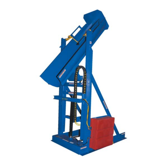
NTRODUCTION Thank you for purchasing an HLD-series hydraulic drum dumper (“drum dumper”, “dumper” or “HLD”) made by Vestil Manufacturing Corporation (“Vestil”). Our dumpers are durable, high-quality products that are rigorously engineered to incorporate safety-enhancing features into an uncomplicated, reliable product design. -
Page 3: Safety Principles
Vestil is not liable for any injury or property damage that occurs as a consequence of failing to apply either: 1) the instructions that appear in this manual; or 2) the information provided on labels affixed to the product. Furthermore, failure to exercise good judgment and common sense might result in property damage, serious personal injury or death. -
Page 4: Installation Instructions
If law enforced where the dumper is used requires you to depart from these directions, Vestil is not responsible for any consequential damages sustained as a result of the installation. Installation requires at least: ... -
Page 5: Operation Instructions
“LOWER TILT” button on the controller to return the chute to the vertical (untilted) position; then press the “LOWER LIFT” to lower the chute to the loading position. 5. Remove the emptied drum. Copyright 2010 Vestil Manufacturing Corp. 5 of 14... -
Page 6: Inspections
Pressure relief valve: opens a path for fluid to flow back to the reservoir if fluid pressure exceeds 3,000psi. Lowering solenoid valve: electrically-operated cartridge valve with an integral screen to keep contaminants from entering the valve. Copyright 2010 Vestil Manufacturing Corp. 6 of 14... -
Page 7: Issues And Solutions
Complete valve assembly Valve 5. Inspect the outside of the valve and inside of the valve cavity (of the manifold; not shown) for debris. Replace the valve if the valve stem is bent. Copyright 2010 Vestil Manufacturing Corp. 7 of 14... - Page 8 Check the oil level in the reservoir. If the surface of the oil is more than 1 to 1½ in. below the fill hole, add oil until it is between 1 and 1½ inches of the fill hole. Copyright 2010 Vestil Manufacturing Corp. 8 of 14...
-
Page 9: Fig. 5 "Single Phase Electrical System Diagram
03/10/03 11/23/2010 HLD manual, operation instructions.doc FIG. 5: Single phase electrical system diagram 208-230 VAC, Single-phase, 60Hz 1½ HP 208-230 VAC 24 FLA; 1725RPM Copyright 2010 Vestil Manufacturing Corp. 9 of 14... -
Page 10: Fig. 6 "3-Phase Electrical System Diagram
03/10/03 11/23/2010 HLD manual, operation instructions.doc FIG. 6: 3-phase electrical system diagram 208-230 VAC, 3-phase, 60Hz 1½ HP 208-230 VAC 24 FLA; 1725RPM Copyright 2010 Vestil Manufacturing Corp. 10 of 14... -
Page 11: Fig. 7 "Hydraulic System Diagram
See purchase order for details 99-153-011 Check valve Lift cylinder See purchase order for details Tilt (dump) cylinder See purchase order for details 01-031-005 Inlet screen 04-023-001 Hydraulic oil reservoir 01-531-001 Velocity fuse Copyright 2010 Vestil Manufacturing Corp. 11 of 14... -
Page 12: Parts List
HLD-116- models 09-021-015 2½ in. x 18 in. long hydraulic cylinder Telescoping cylinder: 15-021-012 HLD-94- models 15-021-013 HLD-116- models 09-537-013 Clamp stop subassembly 12217 ½ in. - 13 x 3½ in. HHCS #5 Copyright 2010 Vestil Manufacturing Corp. 12 of 14... -
Page 13: Troubleshooting Guide
6a. Same as 3e. b. Flow control spool is stuck. b. Same as 5a. 7. Spongy or jerky chute motion. 7. Air in the hydraulic cylinders. 7. Bleed air per procedure described in this manual. Copyright 2010 Vestil Manufacturing Corp. 13 of 14... -
Page 14: Fig. 9 "Product Markings And Labels
B: Label #287 C (both sides) C: Label #250 D & F (inside cover) (alternating corners) D: Label #221 E: Label #204 F: Label #206 G: Label #208 (on both left and right sides) Copyright 2010 Vestil Manufacturing Corp. 14 of 14...


Need help?
Do you have a question about the HLD Series and is the answer not in the manual?
Questions and answers