
Related Manuals for Analog Devices Blackfin A-V EZ-Extender


Summary of Contents for Analog Devices Blackfin A-V EZ-Extender
- Page 1 Blackfin A-V EZ-Extender ® ® Manual Revision 2.1, July 2012 Part Number 82-000870-01 Analog Devices, Inc. One Technology Way Norwood, Mass. 02062-9106...
- Page 2 Analog Devices, Inc. Printed in the USA. Disclaimer Analog Devices, Inc. reserves the right to change this product without prior notice. Information furnished by Analog Devices is believed to be accurate and reliable. However, no responsibility is assumed by Analog Devices for its use;...
- Page 3 Regulatory Compliance The Blackfin A-V EZ-Extender is designed to be used solely in a labora- tory environment. The board is not intended for use as a consumer end product or as a portion of a consumer end product. The board is an open system design which does not include a shielded enclosure and therefore may cause interference to other electrical devices in close proximity.
-
Page 5: Table Of Contents
What’s New in This Manual ............xiii Technical Support ............... xiii Supported Processors ..............xiv Product Information ..............xiv Analog Devices Web Site ............xiv EngineerZone ................xv Related Documents ..............xvi A-V EZ-EXTENDER INTERFACES A-V EZ-Extender Setup ..............1-2 Analog Audio Interface .............. - Page 6 VID_OUT Data Bus Control Jumpers (JP5.3/4, JP5.5/6) ..2-12 PPI0_SYNC1 Direction Setup Jumper (JP6.1/3/5) ....2-12 PPI0_SYNC2 Direction Setup Jumper (JP6.2/4/6) ....2-13 S Enable Jumper (JP7.1/2) ..........2-13 SPORT Data Connect Jumpers (JP7.3/4, JP7.5/6) ....2-13 Blackfin A-V EZ-Extender Manual...
- Page 7 VID_OUT Bus SYNC Enable Jumper (JP8.7/8) ....2-14 AV_RESET Source Jumper (JP9.1/3/5) ........2-14 PPI0_D Direction Setup Jumper (JP9.2/4/6) ......2-15 Audio Loopback Jumpers (JP10.1/2, JP10.3/4) ...... 2-15 A-V EZ-EXTENDER BILL OF MATERIALS A-V EZ-EXTENDER SCHEMATIC INDEX Blackfin A-V EZ-Extender Manual...
- Page 8 Contents viii Blackfin A-V EZ-Extender Manual...
- Page 9 • Load, run, step, halt, and set breakpoints in application programs • Read and write data and program memory • Read and write core and peripheral registers • Plot memory To learn more about Analog Devices development software, go to http://www.analog.com/processors/tools Blackfin A-V EZ-Extender Manual...
-
Page 10: Product Overview
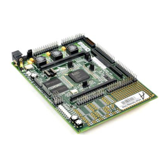
Product Overview Product Overview The Blackfin A-V EZ-Extender is a separately sold daughter board that plugs onto the expansion interface of the ADSP-BF533, ADSP-BF537, or ADSP-BF561 EZ-KIT Lite evaluation system. The extender board aids the design and prototyping phases of the ADSP-BF533, ADSP-BF537, or ADSP-BF561 processor targeted applications. -
Page 11: Purpose Of This Manual
Example programs are available to demonstrate the Blackfin A-V EZ-Extender capabilities. Purpose of This Manual The Blackfin A-V EZ-Extender Manual provides instructions for installing the product hardware (board). The text describes operation and configura- tion of the board components and provides guidelines for running your own code on the A-V EZ-Extender. -
Page 12: Intended Audience
Intended Audience Intended Audience The primary audience for this manual is a programmer who is familiar with Analog Devices processors. This manual assumes that the audience has a working knowledge of the appropriate processor architecture and instruction set. Programmers who are unfamiliar with Analog Devices processors can use this manual but should supplement it with other texts that describe your target architecture. -
Page 13: What's New In This Manual
Preface What’s New in This Manual This is revision 2.1 of the Blackfin A-V EZ-Extender Manual. The manual has been updated to include CCES information. In addition, modifica- tions and corrections based on errata reports against the previous manual revision have been made. -
Page 14: Supported Processors
Supported Processors This extender board supports Analog Devices ADSP-BF533, ADSP-BF537, and ADSP-BF561 Blackfin embedded processors. Product Information Product information can be obtained from the Analog Devices Web site and the online help. Analog Devices Web Site The Analog Devices Web site, , provides information www.analog.com... -
Page 15: Engineerzone
Also note, is a free feature of the Analog Devices Web site that MyAnalog allows customization of a Web page to display only the latest information about products you are interested in. -
Page 16: Related Documents
• ADSP-BF533 Blackfin Processor Hardware Description of the internal processor architec- Reference ture and all register functions • ADSP-BF537 Blackfin Processor Hardware Reference • ADSP-BF561 Blackfin Processor Hardware Reference Blackfin Processor Programming Reference Description of all allowed processor assembly instructions Blackfin A-V EZ-Extender Manual... - Page 17 “A-V EZ-Extender Setup” on page 1-2 • “Analog Audio Interface” on page 1-3 • “Analog Video Interface” on page 1-4 • “Camera Module Interfaces” on page 1-4 • “Flat Panel Display Interface” on page 1-6 • “Example Programs” on page 1-7 Blackfin A-V EZ-Extender Manual...
-
Page 18: A-V Ez-Extender Setup
A-V EZ-Extender Setup It is very important to set up all components of the system containing the Blackfin A-V EZ-Extender, then apply power to the system. Power your system after these steps are completed: 1. Read the applicable design interface section in this chapter—the text provides an overview of the interface capabilities. -
Page 19: Analog Audio Interface
A-V EZ-Extender Interfaces Analog Audio Interface The Blackfin A-V EZ-Extender supports audio applications with the on-board AD1836A multichannel 96 kHz audio codec. The AD1836A codec is a high-performance single-chip device that provides three stereo digital-to-analog converters (outputs) and two stereo analog-to-digital converters (inputs), using Analog Devices patented multibit sigma-delta architecture. -
Page 20: Analog Video Interface
Analog Video Interface Analog Video Interface The Blackfin A-V EZ-Extender supports video input and output applica- tions with an on-board video encoder and decoder. The ADV7179 video encoder provides up to three output channels of analog video, while the ADV7183B video decoder provides up to three input channels of analog video. - Page 21 The interface has been tested with the Kodak KAC-9628 camera. For information about Kodak camera sensors and evaluation boards, go to http://www.kodak.com To connect the Blackfin A-V EZ-Extender to a camera module, first determine the source of the PPI clock. To learn about possible clock set- tings, refer to “PPI Clock Setup Jumpers (JP4.1/2, JP4.3/4, JP4.5/6,...
-
Page 22: Flat Panel Display Interface
“A-V EZ-Extender Schematic” on page B-1. A timing and functional analysis is required to determine whether a spe- cific LCD module can connect to the Blackfin A-V EZ-Extender. An example of display that can connect to the extender is the NEC NL6448BC20-08 display. -
Page 23: Example Programs
Refer to a readme file provided with each exam- ple for more information. CCES users are encouraged to use the example browser to find examples included with the EZ-KIT Lite Board Support Package. Blackfin A-V EZ-Extender Manual... - Page 24 Example Programs Blackfin A-V EZ-Extender Manual...
-
Page 25: A-V Ez-Extender Hardware Reference
The following topics are covered. • “System Architecture” on page 2-2 Describes the extender board configuration and explains how the board components interface with the processor and EZ-KIT Lite. • “Jumpers” on page 2-7 Describes the configuration jumpers. Blackfin A-V EZ-Extender Manual... -
Page 26: System Architecture
System Architecture System Architecture A block diagram of the Blackfin A-V EZ-Extender is shown in Figure 2-1. Not shown in the diagram is the analog audio interface, which is a simple connection between the serial port of the processor and AD1836A audio codec. - Page 27 A-V EZ-Extender Hardware Reference Figure 2-1. A-V EZ-Extender Block Diagram Blackfin A-V EZ-Extender Manual...
- Page 28 System Architecture Table 2-1 summarizes the signals coming and going on the expansion interface connectors. Table 2-1. Signals of Expansion Interface Connectors Net/Bus Name Blackfin A-V EZ-Extender Function Relevant (Direction) Configuration Jumpers Connects the processor’s data pins to the PPI0_D[0:15] PPI0 JP5.3/4...
- Page 29 A-V EZ-Extender Hardware Reference Table 2-1. Signals of Expansion Interface Connectors (Cont’d) Net/Bus Name Blackfin A-V EZ-Extender Function Relevant (Direction) Configuration Jumpers The multifunction net that typically functions as the PPI1_D10 JP3.9/10 (Bi) pin of but, with a jumper, also can connect to the PPI1 JP5.3/4...
- Page 30 System Architecture Table 2-1. Signals of Expansion Interface Connectors (Cont’d) Net/Bus Name Blackfin A-V EZ-Extender Function Relevant (Direction) Configuration Jumpers The SPI serial output data signal used to program the MOSI (Output) control register of the AD1836A audio codec. The SPI serial input data signal used to read the control...
-
Page 31: Jumpers
A-V EZ-Extender Hardware Reference Jumpers Before using the Blackfin A-V EZ-Extender, follow the procedure in “A-V EZ-Extender Setup” on page 1-2. Figure 2-2. Jumper Locations Figure 2-2 shows the jumper header locations. The jumper headers are divided to show each jumper's placement and rotation. The jumpers are described by the pins of the header on which the jumpers can be placed. -
Page 32: Video Test Loopback Jumpers (Jp1.1/2, Jp1.3/4, Jp1.5/6)
Due to the fact that some Blackfin processors feature a built-in 2-wire interface (TWI), while others need to emulate the interface with program- mable flags, two jumpers are provided to plug the A-V EZ-Extender to both TWI sources (see Table 2-3). Blackfin A-V EZ-Extender Manual... -
Page 33: Pdwn Connect Jumper (Jp3.9/10)
Decoder VSYNC Connect Jumper (JP3.13/14) To connect the vertical sync signal of the video decoder to the frame PPI0 sync signal of the processor, install jumper ; otherwise, the JP3.13/14 decoder’s vertical sync is disconnected. Blackfin A-V EZ-Extender Manual... -
Page 34: Encoder Href Connect Jumper (Jp3.15/16)
JP3.19/20 put signals on the bus. VID_IN SNAPSHOT_FODD Disconnect Jumper (JP3.21/22) net of the Blackfin A-V EZ-Extender is a general-pur- SNAPSHOT_FODD pose flag pin. The flag pin connects to (the Kodak camera SNAPSHOT evaluation board’s signal) and... -
Page 35: Ppi Clock Setup Jumpers (Jp4.1/2, Jp4.3/4, Jp4.5/6, Jp4.7/8)
This allows the signals connected to the upper eight bits PPI0 of the PPI data bus of the EZ-KIT Lite to be used elsewhere on the board. To disable and re-use the upper eight bits of the data VID_IN PPI0 busses, install JP5.1/2 Blackfin A-V EZ-Extender Manual 2-11... -
Page 36: Vid_Out Data Bus Control Jumpers (Jp5.3/4, Jp5.5/6)
PPI0_SYNC1 Table 2-7. Setting Direction of PPI0_SYNC1 (JP6.1/3/5) Jumper Location PPI0_SYNC1 Direction Controlled by a flag pin JP6.1/3 Input to the processor JP6.3/5 Uninstalled Output from the processor 2-12 Blackfin A-V EZ-Extender Manual... -
Page 37: Ppi0_Sync2 Direction Setup Jumper (Jp6.2/4/6)
) of the audio codec to the primary and secondary SPORT data ASDATA2 input pins of the processor. The audio codec is driving these pins; with the help of the jumpers, the processor’s pins can be JP7.3/4 JP7.5/6 re-used when the codec is disabled. Blackfin A-V EZ-Extender Manual 2-13... -
Page 38: Vid_Out Bus Sync Source Select Jumpers (Jp8.1/3/5, Jp8.2/4/6)
VID_OUT JP8.7/8 AV_RESET Source Jumper (JP9.1/3/5) The source of ICs reset on the Blackfin A-V EZ-Extender is controlled by either a flag pin or a system reset; the latter also resets the Blackfin proces- sor (see Table 2-9). -
Page 39: Ppi0_D Direction Setup Jumper (Jp9.2/4/6)
Controlled by a flag pin JP9.2/4 Input to the processor JP9.4/6 Uninstalled Output from the processor Audio Loopback Jumpers (JP10.1/2, JP10.3/4) jumpers loop-back audio input to output for JP10.1/2 JP10.3/4 test purposes and should not be installed. Blackfin A-V EZ-Extender Manual 2-15... - Page 40 Jumpers 2-16 Blackfin A-V EZ-Extender Manual...
- Page 41 27MHZ OSC003 DIGI-KEY SG-8002CA-PCC-ND (27.00M) SN74LVC1G32 SN74LVC1G32DBVRE4 SOT23-5 74LVTH16244MT FAIRCHILD 74LVTH16244MTD D TSSOP48 74LVTH16245MT U11,U14,U16 FAIRCHILD 74LVTH16245MTD D TSSOP48 ADP3336ARMZ ANALOG ADP3336ARMZ-REE MSOP8 DEVICES 10MA ANALOG AD1580BRTZ-REEL7 AD1580BRTZ DEVICES SOT23D AD8061ARTZ U3-5 ANALOG AD8061ARTZ-REEL SOT23-5 DEVICES Blackfin A-V EZ-Extender Manual...
- Page 42 SAMTEC TSM-104-01-T-DV IDC4X2_M_SMT FPDI 31PIN 68737-428HLF CON034 IDC 13x2RA SAMTEC SSW-113-02-F-D-RA IDC13x2_F_RA IDC 3X1 IDC3X1 90726-403HLF IDC 2X2 IDC2X2 JP10 SULLINS PBC02DAAN 0.22UF 25V 10% C73,C85,C101, 08053C224FAT 0805 C112,C120-121, C135,C138 33 1/10W 5% 0805 VISHAY CRCW080533R0JNEA Blackfin A-V EZ-Extender Manual...
- Page 43 22 125MW 5% RN1-4 744C083220JP RNS001 147.0K 1/10W 1% DIGI-KEY 311-147KCRTR-ND 0805 76.8K 1/10W 1% DIGI-KEY 311-76.8KCRTR-ND 0805 1.2K 1/16W 5% PANASONIC ERJ-2GEJ122X 0402 0.1UF 16V 10% C1,C4,C7-8,C10-15, 0603YC104KAT2A 0603 C17,C19,C22-23, C26,C30,C32-34, C37-38,C40,C43-44, C46-49,C51-57, C60-69,C75-76,C78, C81,C99,C115, C124,C130-132, C144-145 Blackfin A-V EZ-Extender Manual...
- Page 44 1K 1/10W 5% 0603 R13-14,R18-19,R23- DIGI-KEY 311-1.0KGRTR-ND 237.0 1/10W 1% R64,R70,R106,R110 DIGI-KEY 311-237HRTR-ND 0603 750.0K 1/10W 1% R65,R69,R127,R129 DIGI-KEY 311-750KHRTR-ND 0603 11.0K 1/10W 1% R82,R90,R93-94, DIGI-KEY 311-11.0KHRTR-ND 0603 R123,R126 5.49K 1/10W 1% R75,R83,R86-87, DIGI-KEY 311-5.49KHRTR-ND 0603 R89,R99-101,R116, R119,R131-132 Blackfin A-V EZ-Extender Manual...
- Page 45 C87,C94-96, PANASONIC ECJ-1VC1H221J C125-126 680PF 50V 5% 0603 C84,C88-90, PANASONIC ECJ-1VC1H681J C122-123 2200PF 50V 5% C102,C113-114, PANASONIC ECJ-1VB1H222K 0603 C116,C140,C142 33.0 1/10W 1% R5,R8,R33,R68, DIGI-KEY 311-33.0HRTR-ND 0603 R142,R144-145 2.74K 1/10W 1% R71,R78-80, DIGI-KEY 311-2.74KHRTR-ND 0603 R112-113 Blackfin A-V EZ-Extender Manual...
- Page 46 75.0 1/10W 1% R11-12,R16-17,R21- DALE CRCW060375R0FKEA 0603 22,R26-31 680 1/8W 5% 1206 R114 VISHAY CRCW1206680RFNEA 150.0 1/8W 1% VISHAY CRCW1206150RFKEA 1206 GREEN LED001 LED1 PANASONIC LN1361CTR 3.5MM J8-J9 SWITCH- 35RAPC7JS DUAL_STEREO CRAFT CON066 3.5MM DIGI-KEY CP-3523SJCT-ND STEREO_JACK CON_SJ-3523-SMT Blackfin A-V EZ-Extender Manual...
- Page 47 Blackfin A-V EZ-Extender Schematic ANALOG 20 Cotton Road Nashua, NH 03063 DEVICES PH: 1-800-ANALOGD BLACKFIN A-V EZ-EXTENDER Title TITLE Size Board No. A0193-2004 Date 07-06-2011_15:05 Sheet...
- Page 48 P2_85 CON018 CON019 CON018 CON019 PPI0_D[15:0] 3.3V ANALOG 20 Cotton Road Nashua, NH 03063 10UF 0.1UF DEVICES 0805 0603 PH: 1-800-ANALOGD 10UF 0.1UF BLACKFIN A-V EZ-EXTENDER Title 0805 0603 EXPANSION INTERFACE (1, 2) Size Board No. A0193-2004 Date 07-06-2011_15:16 Sheet...
- Page 49 P3_85 P3_89 P3_90 P3_90 P3_89 CON018 CON019 3.3V ANALOG 20 Cotton Road Nashua, NH 03063 10UF 0.1UF 10UF 0.1UF DEVICES 0805 0603 0805 0603 PH: 1-800-ANALOGD BLACKFIN A-V EZ-EXTENDER Title EXPANSION INTERFACE (3) Size Board No. A0193-2004 Date 07-06-2011_15:16 Sheet...
- Page 50 3.3V 3.3V ANALOG 20 Cotton Road Nashua, NH 03063 DEVICES 0.1UF 0.1UF 0.1UF 0.1UF 0.1UF 0.1UF PH: 1-800-ANALOGD 0603 0603 0603 0603 0603 0603 BLACKFIN A-V EZ-EXTENDER Title DATA ROUTING Size Board No. A0193-2004 74LVTH16245MTD SN74ALVTH16244 SN74ALVTH16244 Date 10-06-2011_09:57 Sheet...
- Page 51 Nashua, NH 03063 DEVICES PH: 1-800-ANALOGD 0.1UF 0.1UF 0.1UF 0.1UF 0.1UF 0.1UF 0.1UF 0603 0603 0603 0603 0603 0603 0603 BLACKFIN A-V EZ-EXTENDER Title FS/CLK CONFIG Size Board No. A0193-2004 OSC SOC SN74LVC1G125 SN74LVC1G125 SN74LVC1G125 74LVTH16245MTD SN74LVC1G125 Date 07-06-2011_15:16 Sheet...
- Page 52 VID_OUT_D15 0603 0603 ENAB GND1 GND2 GND3 0603 0603 0603 GND4 GND5 CON034 3.3V ANALOG 20 Cotton Road Nashua, NH 03063 DEVICES 0.1UF PH: 1-800-ANALOGD 0603 BLACKFIN A-V EZ-EXTENDER Title PPI0 SETUP Size Board No. A0193-2004 SN74AHC1G00 Date 07-06-2011_15:16 Sheet...
- Page 53 0603 0603 0603 0603 0603 0603 COPPER 0603 0603 0603 0603 0603 0603 Nashua, NH 03063 DEVICES PH: 1-800-ANALOGD BLACKFIN A-V EZ-EXTENDER Title VIDEO ENCODER (OUT) AGND2 AGND2 AGND2 AGND2 ADV7179 AD8061 AD8061 AD8061 Size Board No. A0193-2004 Date 07-06-2011_15:16...
- Page 54 DEVICES PH: 1-800-ANALOGD 0.1UF 0.01UF 0.1UF 0.1UF 0.01UF 0.01UF 0.1UF 0.1UF 0.1UF 0603 0603 0603 0603 0603 0603 0603 0603 0603 BLACKFIN A-V EZ-EXTENDER Title AGND2 VIDEO DECODER (IN) Size Board No. A0193-2004 27MHZ OSC SN74LVC1G32 ADV7183 Date 07-06-2011_15:16 Sheet...
- Page 55 0.1UF 0.01UF 0.1UF 0.1UF 0.1UF 0.1UF 0.22UF PH: 1-800-ANALOGD 0603 0603 0603 0603 0603 0603 0603 0603 0805 MSC_COPPER BLACKFIN A-V EZ-EXTENDER Title AUDIO AGND Size Board No. A0193-2004 SN74LVC1G125 SN74LVC1G125 AGND AGND AD1836 12.288MHZ OSC AD8606 Date 21-06-2011_10:31 Sheet...
- Page 56 2.74K 220PF 0603 0603 C116 R108 2200PF 49.9K AD1836_VREF 0603 0603 AGND ANALOG 20 Cotton Road C112 0.22UF Nashua, NH 03063 0805 DEVICES PH: 1-800-ANALOGD BLACKFIN A-V EZ-EXTENDER Title AUDIO OUT(CH1) AGND Size Board No. AD8606 A0193-2004 Date 07-06-2011_15:16 Sheet...
- Page 57 0603 0603 0603 0603 AGND AGND ANALOG 20 Cotton Road Nashua, NH 03063 DEVICES C135 C101 PH: 1-800-ANALOGD 0.22UF 0.22UF 0805 0805 BLACKFIN A-V EZ-EXTENDER Title AUDIO OUT(CH2, CH3) Size Board No. A0193-2004 AGND AGND AD8606 AD8606 Date 07-06-2011_15:16 Sheet...
- Page 58 ANALOG 20 Cotton Road C121 C138 Nashua, NH 03063 0.22UF 0.22UF 0.22UF 0.22UF DEVICES 0805 0805 0805 0805 PH: 1-800-ANALOGD BLACKFIN A-V EZ-EXTENDER Title AUDIO IN(CH1, CH2) Size Board No. AGND AGND AGND AGND A0193-2004 AD8606 AD8606 AD8606 AD8606 Date...
- Page 59 (Blackfin AV EZ-Extender), HREF connect jumper, 2-10 VSYNC connect jumper, 2-10 ADV7183B video decoders connections, HSYNC disconnect jumper, camera module interfaces, 1-4, 2-11 output enable jumper, 2-10 connectors VSYNC connect jumper, DB9, J4 (OmniVision camera), Blackfin A-V EZ-Extender Manual...
- Page 60 2-14 jumper, JP3.15/16 (ADV7179 HREF connect) jumper, 2-10 JP3.17/18 (ADV7179 VSYNC connect) general-purpose flags, 2-10, 2-12, 2-13, jumper, 2-10 2-15 JP3.19/20 (ADV7183B enable) jumper, 2-10 JP3.21/22 (SNAPSHOT_FODD) jumper, 2-5, 2-10 JP3.3/5/7 (TWI source) jumper, 2-4, 2-5, Blackfin A-V EZ-Extender Manual...
- Page 61 PPI0_CLK net, 2-4, 2-11 PPI0_Dx nets, 2-4, 2-15 PPI0_SYNC1-2 Kodak camera direction setup jumpers, 2-12, 2-13 interface, xi, 2-5, nets, connector (P4), PPI1_CLK net, 2-5, 2-11 SNAPSHOT signal, 2-10 PPI1_Dx nets, 1-3, 2-4, 2-5, 2-14 Blackfin A-V EZ-Extender Manual...
- Page 62 SYNC source select jumpers, 2-14 connections, 1-3, voltage selection jumper, receive clock signal (RSCLK0), VS signal, 2-4, receive frame SYNC signal (RFS0), VSYNC connect jumper, 2-9, 2-10 transmit clock signal (TSCLK0), transmit frame SYNC signal (TFS0), Blackfin A-V EZ-Extender Manual...
Need help?
Do you have a question about the Blackfin A-V EZ-Extender and is the answer not in the manual?
Questions and answers