Table of Contents
Advertisement
Quick Links
One Technology Way • P.O. Box 9106 • Norwood, MA 02062-9106, U.S.A. • Tel: 781.329.4700 • Fax: 781.461.3113 • www.analog.com
Evaluating the
AD5423
FEATURES
Fully featured evaluation board for the
On board 2.5 V
ADR4525
reference
ACE
software for control
EVALUATION KIT CONTENTS
EVAL-AD5423SDZ evaluation board
EQUIPMENT NEEDED
SDP-S
controller board
Bench top power supply and connector cables
PC/laptop
DOCUMENTS NEEDED
AD5423
data sheet
ACE
user manual
SOFTWARE NEEDED
ACE
software
PLEASE SEE THE LAST PAGE FOR AN IMPORTANT
WARNING AND LEGAL TERMS AND CONDITIONS.
EVAL-AD5423SDZ
Single Channel, 16-Bit Current or Voltage Output DAC with
HART Connectivity
AD5423
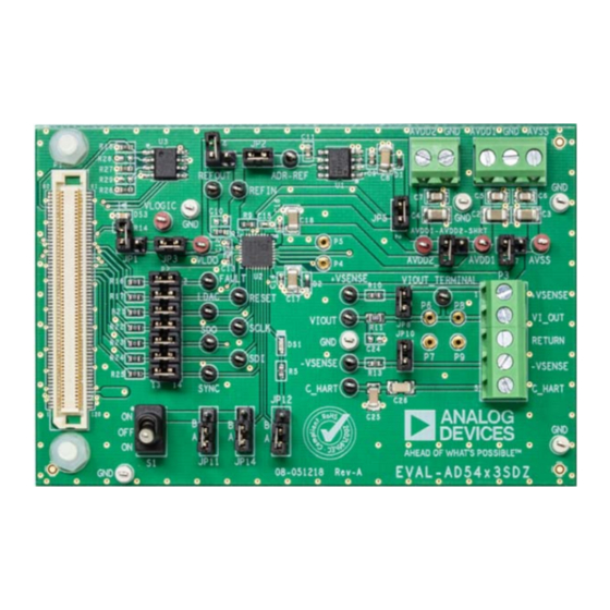
EVALUATION BOARD PHOTOGRAPH
Figure 1.
Rev. 0 | Page 1 of 19
Evaluation Board User Guide
GENERAL DESCRIPTION
This user guide describes the EVAL-AD5423SDZ evaluation
board for the
AD5423
single-channel, 16-bit voltage, 16-bit
current output digital-to-analog converter (DAC).
The EVAL-AD5423SDZ (see Figure 1) requires the
CS1Z
system demonstration platform (SDP-S) board. The
EVAL-AD5423SDZ interfaces to the USB port of the PC via the
SDP-S
board. The Analysis, Control, Evaluation (ACE) software
allows simplified programming of the AD5423, and is available
to use with the EVAL-AD5423SDZ.
For full details on the AD5423, see the
Consult the data sheet in conjunction with this user guide when
using the EVAL-AD5423SDZ.
UG-1554
EVAL-SDP-
AD5423
data sheet.
Advertisement
Table of Contents

Subscribe to Our Youtube Channel
Related Manuals for Analog Devices EVAL-AD5423SDZ


Summary of Contents for Analog Devices EVAL-AD5423SDZ
-
Page 1: Features
EVALUATION KIT CONTENTS CS1Z system demonstration platform (SDP-S) board. The EVAL-AD5423SDZ evaluation board EVAL-AD5423SDZ interfaces to the USB port of the PC via the EQUIPMENT NEEDED SDP-S board. The Analysis, Control, Evaluation (ACE) software allows simplified programming of the AD5423, and is available... -
Page 2: Table Of Contents
Evaluation Board Schematics and Artwork ........ 13 Software Quick Start Procedures ............ 5 Ordering Information ..............18 Installing the ACE Software and EVAL-AD5423SDZ Plugins Bill of Materials ................18 ......................5 REVISION HISTORY 5/2019—Revision 0: Initial Version... -
Page 3: Evaluation Board Hardware
EVAL-AD5423SDZ Evaluation Board User Guide UG-1554 EVALUATION BOARD HARDWARE POWER SUPPLIES SERIAL COMMUNICATION The EVAL-AD5423SDZ requires a number of power supply SDP-S board handles the communication to the EVAL- inputs for the AV , AV , AV , and V pins on the AD5423. - Page 4 UG-1554 EVAL-AD5423SDZ Evaluation Board User Guide Table 2. Link Options for P2 Header Pin No. Position Function 1, 2 Inserted Connects the FAULT signal from the SDP-S to the FAULT pin on the AD5423. Not inserted Disconnects the FAULT signal from the SDP-S to the FAULT pin on the AD5423.
-
Page 5: Software Quick Start Procedures
INSTALLING THE SOFTWARE AND When setting up the evaluation board for the first time, it can be required to install the EVAL-AD5423SDZ plugin. If EVAL-AD5423SDZ PLUGINS the plugin appears as shown in Figure 5, then proceed to The EVAL-AD5423SDZ board uses Analog Devices, Inc., Step 7. - Page 6 If the device is power cycled, or if the USB cable is disconnected and reconnected while the software is open, contact with the EVAL-AD5423SDZ is lost. To regain contact, click the System tab, then click the USB symbol on the EVAL-AD5423SDZ, and then click Acquire.
-
Page 7: Ad5423 Block Diagram And Functions
EVAL-AD5423SDZ Evaluation Board User Guide UG-1554 AD5423 BLOCK DIAGRAM AND FUNCTIONS The EVAL-AD5425SDZ plugin is organized to appear similar to Full descriptions of each block and register setting are available the block diagram shown in the AD5423 data sheet. This graphical... - Page 8 UG-1554 EVAL-AD5423SDZ Evaluation Board User Guide Figure Label Function GUI access on several registers. Pop-ups, dropdown menus, and hexadecimal textboxes are available in the GUI to configure several registers of the AD5423. To write the changes to the device, click Apply Changes. The functions within the GUI that control various registers are described in Table 4.
-
Page 9: Initial Configuration
EVAL-AD5423SDZ Evaluation Board User Guide UG-1554 Figure 8. AD5423 Memory Map in the Software INITIAL CONFIGURATION An initial configuration wizard is available when the AD5423 plugin opens that allows quick configuration of the AD5423, and provides configuration for the clock output in the general-purpose configuration register, the DAC configuration register, and the DAC input register. -
Page 10: Writing To The Adc Configuration Register
UG-1554 EVAL-AD5423SDZ Evaluation Board User Guide WRITING TO THE ADC CONFIGURATION REGISTER UPDATING DIAGNOSTIC RESULTS The procedure to set up and configure the ADC input node is AD5423 has a digital diagnostic results register and an discussed in the AD5423 data sheet. - Page 11 EVAL-AD5423SDZ Evaluation Board User Guide UG-1554 Figure 13. Example Sequences Window Figure 14. Selecting an Example Sequence Rev. 0 | Page 11 of 19...
-
Page 12: Ace Tool Views
UG-1554 EVAL-AD5423SDZ Evaluation Board User Guide TOOL VIEWS software provides additional functionality to the main REGISTER DEBUGGER TOOL view described in this user guide. Open these views from the view Use the register debugger tool to perform raw writes to and menu item on the application toolbar. -
Page 13: Evaluation Board Schematics And Artwork
EVAL-AD5423SDZ Evaluation Board User Guide UG-1554 EVALUATION BOARD SCHEMATICS AND ARTWORK AVDD2 AVDD1 0.1UF VLOGIC VLDO 4.7UF 0.1UF 0.1UF VLDO VLOGIC 0.1UF VF = 1.8V VLDO /RESET IF = 2MA RESET SCLK SCLK FAULT /FAULT /SYNC +VSENSE SYNC 13.7K +V SENSE... - Page 14 UG-1554 EVAL-AD5423SDZ Evaluation Board User Guide AVDD1-AVDD2-SHRT AVDD2 AVDD1 TERMINAL BLOCK DECOUPLING CAPACITORS AVDD1 0.1UF AVDD1/AVSS 4.7UF GND1 AVDD1 AVSS 0.1UF AVSS 4.7UF JP17 AVSS OPTION TO SHORT AVSS TO GND => UNIPOLAR SUPPLY AVDD2_ AVDD2 AVDD2 4.7UF 0.1UF VLOGIC SOURCE OPTIONS VLOGIC 3.3V_SDP...
- Page 15 EVAL-AD5423SDZ Evaluation Board User Guide UG-1554 Board Connections, Address Pins, LDAC and RESET Pins Figure 17. SDP-S Rev. 0 | Page 15 of 19...
- Page 16 -VSENSE 0.1UF C_HART PLACEHOLDER TO EXPERIMENT WITH SETTLING TIME 1727049 THROUGH-HOLE LOAD RESISOR OPTION IN GOLD PINS -VSENSE -VSENSE C_HART C_HART 0.047UF 0.15UF Figure 18. AD5423 Output Stage Figure 19. EVAL-AD5423SDZ Silkscreen, Primary Rev. 0 | Page 16 of 19...
- Page 17 EVAL-AD5423SDZ Evaluation Board User Guide UG-1554 Figure 20. EVAL-AD5423SDZ Layer 1, Primary Figure 21. EVAL-AD5423SDZ Layer 2 and Layer 3 Figure 22. EVAL-AD5423SDZ Layer 4, Secondary Rev. 0 | Page 17 of 19...
-
Page 18: Ordering Information
TL39P0050 Components Analog Devices ADR4525BRZ Analog Devices, IC, ultralow noise, high accuracy voltage reference Analog Devices, IC, single channel, 16-bit current or Analog Devices AD5423BCPZ-RL7 voltage output DAC with highway addressable remote transducer (HART) connectivity IC, 32-kb serial EEPROM Microchip... - Page 19 By using the evaluation board discussed herein (together with any tools, components documentation or support materials, the “Evaluation Board”), you are agreeing to be bound by the terms and conditions set forth below (“Agreement”) unless you have purchased the Evaluation Board, in which case the Analog Devices Standard Terms and Conditions of Sale shall govern. Do not use the Evaluation Board until you have read and agreed to the Agreement.
Need help?
Do you have a question about the EVAL-AD5423SDZ and is the answer not in the manual?
Questions and answers