Advertisement
Quick Links
Advertisement

Subscribe to Our Youtube Channel
Related Manuals for Goodwe DS Series


Summary of Contents for Goodwe DS Series
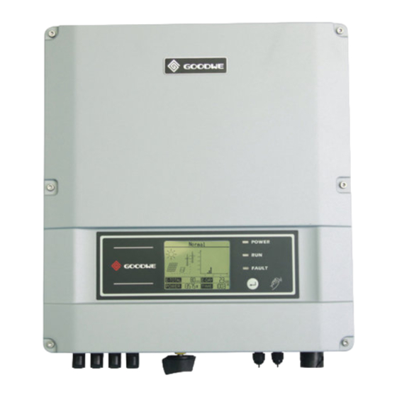
- Page 1 User Manual GOODWE DS SERIES Ver 01...
- Page 2 Table of Contents 1 Symbols ........01 2 Safety .
- Page 3 1 Symbols Caution! - Failure to observe a warning indicated in this manual may result in minor or moderate injury Danger of high voltage and electric shock! Danger of hot surface! Product should not be disposed as normal household waste. This side up- The package must always be transported, handled and stored in such a way that the arrows always point upwards.
- Page 4 2 Safety DS series inverter of Jiangsu GoodWe Power Supply Technology Co.,Ltd. ( hereinafter referred to as GoodWe ) strictly conforms to related safety rules in design and test. As electric and electronic equipment, Safety Regulation shall be followed during installation and maintenance.
- Page 5 GoodWe may deny the obligation of warranty service accordingly. Static electricity may damage electronic components and proper measures shall be adopted to avoid static electricity. The output voltage of proposed PV array should be lower than the inverter maximum rated input voltage;...
- Page 6 Product label and warning symbol shall be clear to read after installation. 3.2 Unpacking When you receive GoodWe inverter, please check if there is any visible external damage on the inverter or any accessories. Please also check if there is anything missing according to the list below.
- Page 7 Expansion Bolt ......7 Flat Head Screw for Lock Plate and RS485 Cover ..5 User Manual .
- Page 8 3.3 Equipment Installation 3.3.1 Selecting the installation position Installation position should be selected based on the following aspects: The installation method and mounting location must be suitable for the inverter's weight and dimensions. Mount on a solid surface. Select a well ventilated place sheltered from direct sun radiation. Install vertically or tilted backward by max 15°.
- Page 9 consideration heat dissipation convenient dismantlement, the minimum clearances around the inverter should be no less than the following value: Upward ....... 300mm Downward .
- Page 10 Figure 3.3.2-1 B Fix the wall mounting bracket on the wall with the expansion bolts in accessory bag. C Carry the inverter by holding the groove on the heat sink. Figure 3.3.2-2 D Place the inverter on the wall-mounted bracket (as illustrated below).
- Page 11 Figure 3.3.2-3 Figure 3.3.2-4 Figure 3.3.2-5 E Insert lock plate into two holes in the heat-sink, then fix the inverter with a padlock and screw M3x8 Figure 3.3.2-6 - 9 -...
- Page 12 3.4 Electrical Connection You must comply with the connection requirement of local regulations. The inverter is integrate with an RCMU according to VDE0126- 1-1/A1. It monitors residual current from the solar module to grid side of inverter. The inverter can automatically differentiate between fault current and normal capacitive leakage currents.
- Page 13 Insert Line wire to Pin 1, Neutral wire to Pin 2 and Ground wire to Pin Figure 3.4.1-2 After fastening all screws, reassemble the female connector of the AC wire connector. Connect the female connector of the AC wire connector to the Male connector on the inverter.
- Page 14 Depiction Size A External diameter of the wire 12mm-25mm B Sectional area of conducting materials Max.6mm C Length of bare wire Approx.10mm E AC output connection diagram Please tighten the screw with a screw driver until the head of the screw is inside the connector.
- Page 15 If use Phoenix contact connectors for PV array terminals, installation as follows. Female side connector (PV+) Male side connector (PV-) Both types of connectors must be equipped in pair strictly according to above graphs Figure 3.4.2-1 Figure 3.4.2-2 1. Insert the stripped PV conductor - 13 -...
- Page 16 Figure 3.4.2-3 2. Press down on the spring and snap in Figure 3.4.2-4 3.Tighten the screw connection then the terminal can be connected to the inverter side - 14 -...
- Page 17 Figure 3.4.2-5 Can only be released using a screwdriver If use Multi-contact connectors for PV array terminals, installation as follows. Female side connector (PV+) Male side connector (PV-) Both types of connectors must be equipped in pair strictly according to above graphs - 15 -...
- Page 18 - 16 -...
- Page 19 Figure 3.4.2-6 Tighten the screw connection then the terminal can be connected to the inverter side Figure 3.4.2-7 Compress the two snap-in springs by hand and release Regarding the inverter equiped with DC switch, please ensure the switch is in "OFF" position before connecting the inverter with PV panels.
- Page 20 Before connecting the PV panels, please ensure the plug connectors have the correct polarity. Incorrect polarity connection could permanently damage the unit. Checks short-circuit current of the PV string. The total short- circuit current of the PV string cannot exceed the inverter’s maximum DC current.
Need help?
Do you have a question about the DS Series and is the answer not in the manual?
Questions and answers