Goodwe DNS G3 Series User Manual
Grid-tied pv inverter
Hide thumbs
Also See for DNS G3 Series:
- Quick installation manual (105 pages) ,
- Quick installation manual (105 pages)
Table of Contents
Advertisement
Quick Links
Advertisement
Table of Contents

Related Manuals for Goodwe DNS G3 Series


Summary of Contents for Goodwe DNS G3 Series
- Page 1 User Manual Grid-Tied PV Inverter DNS G3 Series V1.0-2022-03-22...
- Page 2 Copyright Statement User Manual V1.0-2022-03-22 Trademarks and other GOODWE trademarks are trademarks of GoodWe Technologies Co.,Ltd. All other trademarks or registered trademarks mentioned in this manual are owned by GoodWe Technologies Co.,Ltd. NOTICE The information in this user manual is subject to change due to product updates or other reasons.
-
Page 3: Table Of Contents
CONTENT User Manual V1.0-2022-03-22 CONTENT 1 About This Manual ..............1 1.1 Applicable Model ..................1 1.2 Target Audience ....................1 1.3 Symbol Definition ..................2 1.4 Updates ......................2 2 Safety Precaution ..............3 2.1 General Safety ....................3 2.2 DC Side: ......................3 2.3 AC Side ......................3 2.4 Inverter Installation ..................4 2.5 Personal Requirements ................4 2.6 EU Declaration of Conformity ..............5... - Page 4 CONTENT User Manual V1.0-2022-03-22 6 Electrical Connection ............16 6.1 Safety Precaution ..................16 6.2 Connecting the PE Cable ................17 6.3 Connecting the PV Input Cable ..............17 6.4 Connecting the AC Output Cable .............20 6.5 Communication ..................24 6.5.1 Communication Network Introduction ............24 6.5.1 Connecting the Communication Cable (optional) ...........25 6.5.3 Installing the Communication Module (optional) ...........27 6.54 Connecting the USB-RS485 Cable ..............27...
-
Page 5: About This Manual
All the installers and users have to be familiar with the product features, functions, and safety precautions. This manual is subject to update without notice. For more product details and latest documents, visit https://en.goodwe.com/. 1.1 Applicable Model This manual applies to the listed inverters below (DNS G3 or Inverter for short):... -
Page 6: Symbol Definition
Disclaimer User Manual V1.0-2022-03-22 1.3 Symbol Definition Different levels of warning messages in this manual are defined as follows: DANGER Indicates a high-level hazard that, if not avoided, will result in death or serious injury. WARNING Indicates a medium-level hazard that, if not avoided, could result in death or serious injury. CAUTION Indicates a low-level hazard that, if not avoided, could result in minor or moderate injury. -
Page 7: Safety Precaution
• Strictly follow the installation, operation, and configuration instructions in this manual. The manufacturer shall not be liable for equipment damage or personal injury if you do not follow the instructions. For more warranty details, please visit https://en.goodwe.com/ warranty. 2.2 DC Side: DANGER Connect the DC cables using the delivered PV connectors. -
Page 8: Inverter Installation
Safety Precaution User Manual V1.0-2022-03-22 2.4 Inverter Installation DANGER • Do not apply mechanical load to the terminals, otherwise the terminals can be damaged. • All labels and warning marks should be visible after the installation. Do not scrawl, damage, or cover any label on the device. •... -
Page 9: Eu Declaration Of Conformity
Safety Precaution User Manual V1.0-2022-03-22 2.6 EU Declaration of Conformity GoodWe Technologies Co., Ltd. hereby declares that the inverter with wireless communication modules sold in the European market meets the requirements of the following directives: • Radio Equipment Directive 2014/53/EU (RED) •... -
Page 10: Product Introduction
Product Introduction User Manual V1.0-2022-03-22 3 Product Introduction 3.1 Application Scenarios The DNS G3 inverter is a single-phase PV string grid-tied inverter. The inverter converts the DC power generated by the PV module into AC power and feeds it into the utility grid. The intended use of the inverter is as follows: Circuit Utility... -
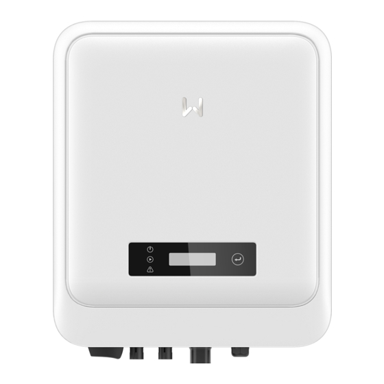
Page 11: Appearance
User Manual V1.0-2022-03-22 Product Introduction 3.4 Appearance 3.4.1 Parts Parts Description DC Switch Start or stop DC input. Only for Australia. Turn the DC switch to OFF and DC Switch Lock lock it to avoid electric shock when you have to work on the inverter. -
Page 12: Dimensions
Product Introduction User Manual V1.0-2022-03-22 3.4.2 Dimensions 3.4.3 Indicators With LCD Indicator Status Description ON = Wi-Fi IS CONNECTED/ACTIVE BLINK 1 = Wi-Fi SYSTEM IS RESETTING BLINK 2 = NOT CONNECTED TO THE ROUTER Power BLINK 4 = Wi-Fi SERVER PROBLEM BLINK = RS485 IS CONNECTED OFF = Wi-Fi IS NOT ACTIVE ON = THE INVERTER IS FEEDING POWER... -
Page 13: Nameplate
User Manual V1.0-2022-03-22 Product Introduction Indicators Status Description ON= WIRELESS IS CONNECTED/ACTIVE BLINK 1 = WIRELESS SYSTEM IS RESETTING BLINK 2 = WIRELESS ROUTER PROBLEM SEMS BLINK 4 = WIRELESS SERVER PROBLEM BLINK = RS485 IS CONNECTED OFF= WIRELESS IS NOT ACTIVE ON= A FAULT HAS OCCURRED Faulty OFF= NO FAULT... -
Page 14: Check And Storage
Check and Storage User Manual V1.0-2022-03-22 Check and Storage 4.1 Check Before Receiving Check the following items before receiving the product. 1. Check the outer packing box for damage, such as holes, cracks, deformation, and other signs of equipment damage. Do not unpack the package and contact the supplier as soon as possible if any damage is found. -
Page 15: Storage
Check and Storage User Manual V1.0-2022-03-22 4.3 Storage If the equipment is not to be installed or used immediately, please ensure that the storage environment meets the following requirements: 1. Do not unpack the outer package or throw the desiccant away. 2. -
Page 16: Installation
Installation User Manual V1.0-2022-03-22 5 Installation 5.1 Installation Requirements Installation Environment Requirements 1. Do not install the equipment in a place near flammable, explosive, or corrosive materials. 2. Install the equipment on a surface that is solid enough to bear the inverter weight. 3. - Page 17 Installation User Manual V1.0-2022-03-22 Mounting Support Requirements • The mounting support shall be nonflammable and fireproof. • Make sure that the support surface is solid enough to bear the product weight load. • Do not install the product on the support with poor sound insulation to avoid the noise generated by the working product, which may annoy the residents nearby.
- Page 18 Installation User Manual V1.0-2022-03-22 Installation Tool Requirements The following tools are recommended when installing the equipment. Use other auxiliary tools on site if necessary. DC terminal Goggles Safety shoes Dust mask Safety gloves crimping tool DC wiring Diagonal pliers Wire stripper Hammer drill Heat gun wrench...
-
Page 19: Inverter Installation
Installation User Manual V1.0-2022-03-22 5.2 Inverter Installation 5.2.1 Moving the Inverter CAUTION Move the inverter to the site before installation. Follow the instructions below to avoid personal injury or equipment damage. 1. Consider the weight of the equipment before moving it. Assign enough personnel to move the equipment to avoid personal injury. -
Page 20: Electrical Connection
Installation User Manual V1.0-2022-03-22 Only for Australia. 6 Electrical Connection 6.1 Safety Precaution DANGER • Disconnect the DC switch and the AC output switch of the inverter to power off the inverter before any electrical connections. Do not work with power on. Otherwise, an electric shock may occur. -
Page 21: Connecting The Pe Cable
Electrical Connection User Manual V1.0-2022-03-22 6.2 Connecting the PE Cable WARNING • The PE cable connected to the enclosure of the inverter cannot replace the PE cable connected to the AC output port. Make sure that both of the two PE cables are securely connected. - Page 22 Electrical Connection User Manual V1.0-2022-03-22 Click NOTICE Seal the PV input terminals using waterproof covers when they are not to be used. Otherwise, the ingress protection rating will be influenced. Connecting the DC Input Cable Step 1 Prepare DC cables. Step 2 Crimp the crimp contacts.
- Page 23 Electrical Connection User Manual V1.0-2022-03-22 Click Click Stäubli MC4 PV connector ≤S≤6mm Click Click...
-
Page 24: Connecting The Ac Output Cable
Electrical Connection User Manual V1.0-2022-03-22 6.4 Connecting the AC Output Cable WARNING • Do not connect loads between the inverter and the AC switch directly connected to the inverter. • The Residual Current Monitoring Unit (RCMU) is integrated into the inverter. The inverter will disconnect the utility grid rapidly once it detects any leak current over the permissible range. - Page 25 Electrical Connection User Manual V1.0-2022-03-22 NOTICE Install one AC circuit breaker for each inverter. Multiple inverters cannot share one AC circuit breaker. WARNING • Pay attention to the silkscreens L, N, PE on the AC terminal. Connect the AC cables to the corresponding terminals.
- Page 26 Electrical Connection User Manual V1.0-2022-03-22 AC Connector-1 Click...
- Page 27 Electrical Connection User Manual V1.0-2022-03-22 AC Connector-2 Copper, Click NOTICE • Make sure that the cable is connected correctly and securely. Clear the debris after completing the connection. • Seal the AC output terminal to ensure the ingress protection rating.
-
Page 28: Communication
Electrical Connection User Manual V1.0-2022-03-22 6.5 Communication 6.5.1 Communication Network Introduction Power Limit Network The PV station generates power for self-consumption, but the electric equipment cannot consume all the generated power. The inverter can monitor the on-grid electric data in real-time and adjust the output power via a smart meter to avoid the residual current feeding back to the utility grid. -
Page 29: Connecting The Communication Cable (Optional)
Electrical Connection User Manual V1.0-2022-03-22 6.5.1 Connecting the Communication Cable (optional) Communication Terminal Definition Function Type 1: RS485+ Used to connect multi inverters or the RS485 RS485 2: RS485- RS485 port on the data logger. The port is reserved in compliance 3: RSD+ with grid regulations in Europe. - Page 30 Electrical Connection User Manual V1.0-2022-03-22 Meter RS485 Remote Shutdown Dry contact DRED RS485 Meter 1: RS485+ 11: Meter+ 2: RS485- 12: Meter - Remote Shutdown 13: CT+ 3: RSD+ 14: CT- 4: RSD- Dry contact DRED 5: I/O1+ 15: DRM1/5 6: I/O1- 16: DRM2/6 7: I/O2+...
-
Page 31: Installing The Communication Module (Optional)
WiFi kit, LAN kit, 4G kit, GPRS, Bluetooth Kit, Wi-Fi/LAN Kit module: optional. Notice Refer to the delivered communication module user manual to get more introduction to the module. For more detailed information, visit https://en.goodwe.com. 6.54 Connecting the USB-RS485 Cable USB-RS485 cable: Only for Brazil. -
Page 32: Equipment Commissioning
Equipment Commissioning User Manual V1.0-2022-03-22 7 Equipment Commissioning 7.1 Check Before Power ON Check Item The product is firmly installed at a clean place that is well-ventilated and easy to operate. The PE, DC input, AC output, and communication cables are connected correctly and securely. -
Page 33: System Commissioning
System Commissioning User Manual V1.0-2022-03-22 8 System Commissioning 8.1 Indicators and Buttons With LCD Indicator Status Description ON = Wi-Fi IS CONNECTED/ACTIVE BLINK 1 = Wi-Fi SYSTEM IS RESETTING BLINK 2 = NOT CONNECTED TO THE ROUTER Power BLINK 4 = Wi-Fi SERVER PROBLEM BLINK = RS485 IS CONNECTED OFF = Wi-Fi IS NOT ACTIVE ON = THE INVERTER IS FEEDING POWER... -
Page 34: Setting Inverter Parameters Via Lcd
System Commissioning User Manual V1.0-2022-03-22 8.2 Setting Inverter Parameters via LCD NOTICE • Inverter firmware version shown in this document is V1.00.00. Coummunication version: V1.00. The screenshots are for reference only. The actual interface may differ. • The name, range, and default value of the parameters are subject to change or adjustment. The actual display prevails. -
Page 35: Lcd Menu Introduction
System Commissioning User Manual V1.0-2022-03-22 8.2.1 LCD Menu Introduction This part describes the menu structure, allowing you to view inverter information and set parameters more conveniently. Normal Set language Pac=xxx W Set Safety Short press Short press xxxx-xx-xx Set Date xx:xx:xx Set Time Short press... -
Page 36: Inverter Parameter Introduction
System Commissioning User Manual V1.0-2022-03-22 8.2.2 Inverter Parameter Introduction Parameters Description Normal Home page. Indicates the real-time power of the inverter. 2022-02-14 Check the time of the country/region. 09:01:10 VPv1 Check the DC input voltage of the inverter. IPv1 Check the DC input current of the inverter. Check the voltage of the utility grid. -
Page 37: Upgrading The Firmware Via Usb Flash Disk
WIFi module or GPRS module. Commonly used functions are as follows: 1. Check the operating data, software version, alarms, etc. 2. Set grid parameters, communication parameters, etc. 3. Equipment maintenance. Visit https://en.goodwe.com/ or scan the QR code to read the user manual. SolarGo App User Manual SolarGo App https://www.goodwe.com/Ftp/... -
Page 38: Maintenance
09 Maintenance User Manual V1.0-2022-03-22 9 Maintenance 9.1 Power Off the Inverter DANGER • Power off the inverter before operations and maintenance. Otherwise, the inverter may be damaged or electric shocks may occur. • Delayed discharge. Wait until the components are discharged after power off. Step 1 (optional) Send shutdown command to the inverter. - Page 39 Maintenance User Manual V1.0-2022-03-22 Fault Cause Solutions 1. Utility grid power fails. 1. The alarm is automatically cleared after 2. The AC cable is the grid power supply is restored. Utility Loss disconnected, or 2. Check whether the AC cable is connected the AC breaker is and the AC breaker is on.
- Page 40 09 Maintenance User Manual V1.0-2022-03-22 Fault Cause Solutions 1. If the problem occurs occasionally, the utility grid may be abnormal temporarily. The inverter will recover automatically after detecting that the utility grid is normal. 2. If the problem occurs frequently, check The grid voltage whether the grid voltage is within the is lower than...
- Page 41 Maintenance User Manual V1.0-2022-03-22 Fault Cause Solutions 1. If the problem occurs occasionally, the utility grid may be abnormal temporarily. The inverter will recover automatically after detecting that the utility grid is normal. Utility grid 2. If the problem occurs frequently, check exception.
- Page 42 09 Maintenance User Manual V1.0-2022-03-22 Fault Cause Solutions The utility grid is disconnected. The utility grid 1. Check whether the utility grid is is disconnected disconnected. Anti-islanding according to the 2. Contact the dealer or the after-sales safety regulations, service. but the grid voltage is maintained due to the loads.
- Page 43 Maintenance User Manual V1.0-2022-03-22 Fault Cause Solutions 1. The PV string is short-circuited 1. Check whether the resistance of the PV to PE. string to PE exceeds 50kΩ. If no, check the 2. The PV system short circuit point. Low Insulation is in a moist 2.
- Page 44 09 Maintenance User Manual V1.0-2022-03-22 Fault Cause Solutions Disconnect the AC output switch and DC input The sampling of GFCI HCT Check switch, then connect them 5 minutes later. the GFCI HCT is abnormal Contact the dealer or the after-sales service if abnormal.
-
Page 45: Routine Maintenance
Maintenance User Manual V1.0-2022-03-22 Fault Cause Solutions 1. The PV voltage is too high. Disconnect the AC output switch and DC input 2. The sampling switch, then connect them 5 minutes later. BUS Overvoltage of the inverter Contact the dealer or the after-sales service if BUS voltage is the problem persists. -
Page 46: Technical Parameters
Technical Parameters User Manual V1.0-2022-03-22 10 Technical Parameters Technical GW3000-DNS-30 GW3600-DNS-30 GW4200-DNS-30 GW5000-DNS-30 Parameters Input Max.Input Power 4,500 5,400 6,300 7,500 Max.Input Voltage MPPT Operating 40~560 40~560 40~560 40~560 Voltage Range (V) MPPT Voltage Range at Nominal 100~500 120~500 140~500 165~500 Power (V) Start-up Voltage (V) - Page 47 Technical Parameters User Manual V1.0-2022-03-22 Max Power at 40℃ (Including AC 3,000 3,600 4,200 5,000 Overload)(W)(Only for Brazil) Nominal Output 220/230/240 220/230/240 220/230/240 220/230/240 Voltage (V) 196~311 196~311 196~311 196~311 Output Voltage (According to (According to (According to (According to Range (V) local standard) local standard)
- Page 48 Technical Parameters User Manual V1.0-2022-03-22 Anti-islanding Integrated Protection AC Overcurrent Integrated Protection AC Short Circuit Integrated Protection AC Overvoltage Integrated Protection DC Switch Integrated DC Surge Type III(Type II Optional) Protection AC Surge Type III(Type II Optional) Protection AFCI Optional Emergency Power Optional Remote Shutdown...
- Page 49 Technical Parameters User Manual V1.0-2022-03-22 Ingress Protection IP66 Rating Anti-corrosion Class DC Connector MC4 (4~6mm AC Connector Plug and play connector (Max.6 mm²) Environmental 4K4H Category Pollution Degree Overvoltage DC II / AC III Category Protective Class The Decisive PV: C AC: C Com: A Voltage Class (DVC) Country of Manufacture(Only...
- Page 50 Technical Parameters User Manual V1.0-2022-03-22 Nominal Output Apparent 6,000 5,000 6,000 Power (VA) Max. AC Active Power (W)*2 6,600 5,500 6,600 Max. AC Apparent Power (VA)*3 6,600 5,500 6,600 Nominal Power at 40℃(W)(Only 6,000 5,000 6,000 for Brazil) Max Power at 40℃ (Including 6,000 5,000 6,000...
- Page 51 Technical Parameters User Manual V1.0-2022-03-22 Type III(Type II DC Surge Protection Type III Type III Optional) Type III(Type II AC Surge Protection Type III Type III Optional) AFCI Optional Emergency Power Off Optional Remote Shutdown Optional Power Supply at Night Optional General Data Operating Temperature Range...
- Page 52 Official Website GoodWe Technologies Co.,Ltd. No. 90 Zijin Rd., New District, Suzhou, 215011, China T: 400-998-1212 www.goodwe.com service@goodwe.com Contact Information...
Need help?
Do you have a question about the DNS G3 Series and is the answer not in the manual?
Questions and answers