
Related Manuals for Mitsubishi Electric ecodan ECOSLIM150L-PP-MEUK


Summary of Contents for Mitsubishi Electric ecodan ECOSLIM150L-PP-MEUK
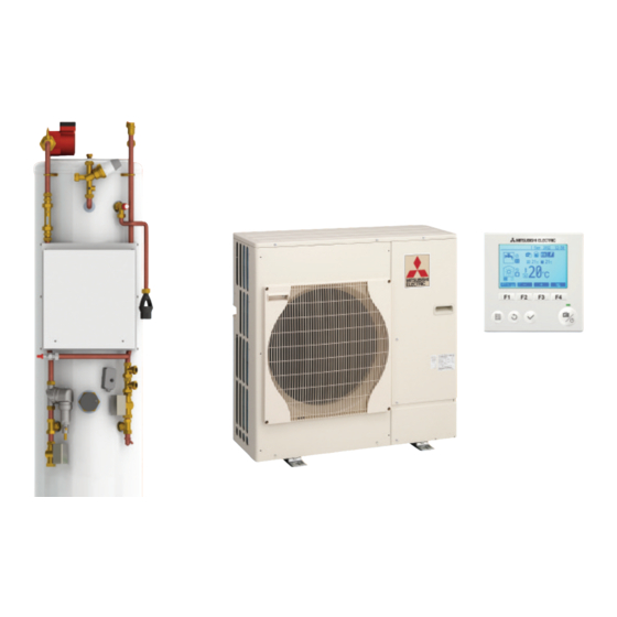
- Page 1 Mitsubishi Electric Pre-Plumbed Slimline Cylinder Installation Manual IMPORTANT! This manual contains commissioning and maintenance records and must be left with the equipment.
-
Page 3: Table Of Contents
Contents Introduction Page 4 Key Facts Page 5 Equipment Checklist Page 6 Cylinder Installation Requirements Page 7 Pipework Configuration Page 9 Heat Pump System Overview Page 10 How a Heat Pump Works Page 11 Cylinder Technical Data Page 12 Ecodan Technical Data Page 13 ®... -
Page 4: Introduction
Introduction Important Note to the Installer The Mitsubishi Electric Pre-Plumbed Slimline Cylinder is specifically designed to be installed in conjunction with an Ecodan air source heat pump. The Mitsubishi Electric Pre-Plumbed Slimline Cylinder is available with an indirect ® single coil. -
Page 5: Key Facts
Key Facts This version of the Mitsubishi Electric Pre-Plumbed Slimline Cylinder is the fourth generation in terms of its control systems and the design of key mechanical components. As you would expect there have been many technological changes based around our experience of producing premium quality cylinders optimised to work with our Ecodan range of air source heat pumps. -
Page 6: Equipment Checklist
Equipment Checklist You will receive the following components fitted to every Mitsubishi Electric Pre-Plumbed Slimline Cylinder The standard Slimline Cylinder comes with a single Factory Fitted Components UPS2 25-60 circulation pump and a pair of zone FTC4 Control Centre valves - one hot water zone and one heating zone. -
Page 7: Cylinder Installation Requirements
Water Supply The water supply should be checked to ensure the pressure and flow rate are suitable for the Mitsubishi Electric Pre-Plumbed Slimline Cylinder (Maximum flow rate = 50 litres/minute, Maximum pressure = 3 bar). If necessary consult the local water company regarding the likely pressure and flow rate availability. - Page 8 Cylinder Installation Requirements 1. The water quality shall be in accordance with European Council Directive 98/83 EC, or revised version at the date of installation, and is not fed with water from a private supply. Particular: Chloride content: Max. 250 mg/l Sulphate content: Max.
-
Page 9: Pipework Configuration
Pipework Configuration Heat Pump Return Domestic Hot Water Cold Mains Water Heat Pump Flow Pressure Relief Tundish Heating Zone 1 Flow Heating Zone 2 Return Heating Zone 2 Flow Heating Zone 1 Return Domestic Hot Water Drain Pre-Plumbed Slimline Cylinder Installation Manual... -
Page 10: Heat Pump System Overview
Option 3 is known as room compensation and is only available when using a Mitsubishi Electric thermostat. In this mode the FTC4 will calculate the optimum flow temperature. -
Page 11: How A Heat Pump Works
How a Heat Pump Works The heat pump essentially works in the same way as your refrigerator but in reverse. The Ecodan is hermetically ® sealed (no refrigeration piping involved) with R410A refrigerant, the cycle it completes to produce heat is known as the vapour compression refrigeration cycle: Step 1 The first phase begins with the refrigerant being cold and low pressure. -
Page 12: Cylinder Technical Data
Cylinder Technical Data ECOSLIM- ECOSLIM- PRE-PLUMBED SLIMLINE CYLINDER UNIT 150L-PP-MEUK 180L-PP-MEUK Nominal hot water volume (litres) Water Flow Rate (l/min) W50 - W85 14.3 - 25.8 14.3 - 25.8 Pump 1 x Grundfos UPS2 25-60 1 x Grundfos UPS2 25-60 Connection Size (mm) Heating / DHW (mm) Primary Expansion Vessel (Litres) Charge Pressure (MPa (Bar)) -
Page 13: Ecodan ® Technical Data
Ecodan Technical Data ® Model PUHZ-W50VHA-BS PUHZ-W85VHA(2)-BS PUHZ-HW140VHA(2)-BS / PUHZ-HW140YHA(2)-BS Dimensions (mm) Width 1020 Depth 330+30* 330+30* 330+30* Height 1350 Weight (kg) 134 / 148 Airflow (m3/min) Nominal sound level (dBA) 45 ◊ 48 ◊ 53 ◊ Low noise mode (dBA) @ 7°C Guaranteed operating range (Outdoor) - 15 ~ +35°C - 20 ~ +35°C... -
Page 14: Ecodan ® Capacity Drop Offs
Ecodan Capacity Drop Offs ® Power (kW) Ambient Air PUHZ-W50 PUHZ-W85 PUHZ-HW140 Temperature *W35 *W45 *W55 W35* W45* W55* W35* W45* W55* -15ºC -7ºC 2ºC 7ºC * Where W35 is a flow temperature of 35ºC / Where W45 is a flow temperature of 45ºC / Where W55 is a flow temperature of 55ºC PUHZ-W50 Fig 2.4 -15.00... -
Page 15: Low Noise Mode
Low Noise Mode To activate low noise mode an optional 3 wire adaptor is required (PAC-SC36NA). This can either be wired into a manual switch or a timed version. The level of low noise mode which will be activated (as shown in the relevant graphs below and over the page) is determined by the combination of DIP switch settings (SW5-1 and SW5-2) on the outdoor unit as shown below. - Page 16 Low Noise Mode (continued) PUHZ-W85VHA2 BS Noise Curve PUHZ-HW140VHA2/YHA2 BS Noise Curve Pre-Plumbed Slimline Cylinder Installation Manual...
-
Page 17: Dimensional Drawing
Dimensional Drawing Top of AAV (Highest point) Domestic Hot Water Drain Mains Cold Feed and Heat Pump Flow Heating Zone 1 Return Hot Water Outlet Heating Zone 2 Return Tundish Outlet Automatic Bypass Valve Heating Zone 1 Flow Balanced Cold Feed Heating Zone 2 Flow MODEL 150L-PP-MEUK... -
Page 18: Heat Emitters
Please note that heat pumps provide lower flow temperatures to radiators than a conventional gas or oil boiler, the best performance is achieved with lower flow temperatures, Mitsubishi Electric recommend that flow temperatures in space heating should not exceed 45ºC if practical. Rather than the radiators turning on/off locally as with a fossil fuel boiler, heat pumps provide a more consistent lower flow temperature which allows for more efficiency and greater comfort. - Page 19 Electric recommend the use of such items. They can also be utilised on heating circuits if for example constant flow rates and variable flow rates need to be achieved on a single system. For further information and advice on the selection of hydraulic separators please contact Mitsubishi Electric pre-sales technical on 01707 278666. Pre-Plumbed Slimline Cylinder Installation Manual...
-
Page 20: Ecodan ® Only System Schematic
Ecodan Only System Schematic ® Isolation Valve Site Installed ZONE 1 FLOW (THW1) ECODAN FLOW DHW FLOW (THW2) ECODAN RETURN ZONE 1 RETURN FLOW METER PUMP MAG FILTER DHW RETURN Legend Motorised Two Port Valve Thermistor Pump Pipework (Field Supply) Factory Pipework Flow Meter Mag Filter... -
Page 21: Fossil Fuel Boiler And Ecodan ® System Schematics
Fossil Fuel Boiler and Ecodan System Schematics ® (THWB1) *3 FOSSIL FUEL BOILER *4 (THWB2) *3 (THW6) ZONE 1 FLOW (THW8) ZONE 2 FLOW LOW LOSS HEADER (THW1) *1 ECODAN FLOW DHW FLOW FLOW METER (THW7) (THW2) *1 ECODAN RETURN PUMP FLOW ZONE 1 RETURN... -
Page 22: Controller Options
The main controller is also used for servicing purposes. This facility is accessed via password protected service menus. To provide the best efficiency Mitsubishi Electric recommends using room compensation function. To use this function a room thermistor needs to be present in a main living area. This can be done in a number of ways the most convenient are detailed below. - Page 23 Control option B FTC4 This option features the main controller, the Mitsubishi Electric thermistor and a This option features the main controller, the Mitsubishi Electric thermistor and a locally (Master) supplied thermostat that are wired to FTC-4 (Master). locally supplied thermostat that are wired to FTC4 (Master).
-
Page 24: Cylinder And Hydraulic Components Install Guidance
Secondary Circulation The Mitsubishi Electric Pre-Plumbed Slimline Cylinder can be used with a secondary circulation pump. An appropriate WRAS approved bronze circulator should be used in conjunction with a non-return valve to prevent backflow. On large secondary circulation systems it may be necessary to incorporate an extra expansion vessel into the circuit to accommodate the increased system water volume, details of how to calculate this are found later in this manual. - Page 25 Compact Filter - Intaeco Duco All Mitsubishi Electric Pre-Plumbed Slimline Cylinders now have the Intaeco Duco compact filter factory fitted on the heat pump return pipework which is common to both heating and hot water zones. This has been done...
-
Page 26: Automatic Bypass Valve
Automatic Bypass Valve The Mitsubishi Electric Pre-Plumbed Slimline Cylinder has a spring differential automatic bypass valve fitted as standard between the primary flow and return. This serves two purposes; it allows for the minimum flow rate of the Ecodan unit to be maintained and hence ®... -
Page 27: Expansion Vessel
Expansion Vessel Each Mitsubishi Electric pre-plumbed cylinder is supplied with a suitably sized expansion vessel (white) for the associated volume of potable water. ECOSLIM-150L-PP-MEUK ECOSLIM-180L-PP-MEUK EXPANSION VESSEL VOLUME 12 litres 19 Litres In the case of a sealed primary circuit an additional expansion vessel will be required, this needs to be sized to accommodate the expansion within the entire heat emitter circuit and associated pipework. -
Page 28: Ancillary Components
Anti-vibration mountings (i.e. Tico-pad) should be installed under the mountings of the heat pump to prevent excessive vibration. Rubber anti-vibration fix it feet can be purchased from Mitsubishi Electric which have the dual purpose of raising the unit from ground level (useful in snow prone locations) and reducing vibration. -
Page 29: Discharge Arrangement
Discharge Arrangement Position the inlet control group so that the discharge from both safety valves can be joined together via a 15mm end feed Tee. Connect the Tundish and route the discharge pipe. The discharge pipework must be routed in accordance with Part G3 of schedule 1 of the Building Regulations. - Page 30 Discharge Arrangement (continued) The discharge pipe (D2) from the tundish should be of metal or other material that has been demonstrated to be capable of withstanding temperatures of the water discharged. The discharge pipe (D2) should be at least one pipe size larger than the nominal outlet size of the safety device unless its total equivalent hydraulic resistance exceeds that of a straight pipe 9m long i.e.
-
Page 31: Ecodan ® Installation
Ecodan Installation ® Safety Precautions:- WARNING: Precautions that must be observed to prevent injuries or death. CAUTION: Precautions that must be observed to prevent damages to the unit. After installation, perform the test run to ensure normal operation. Then explain to your customer the “Safety Precautions” use and maintenance of the unit based on the information in the Operation Manual. - Page 32 Ecodan Installation ® (continued) Do not install the unit where combustible gas accumulates around the unit, it may cause fire or explosion. The outdoor unit produces condensation during the heating operation. Make sure to provide drainage around the outdoor unit if such condensation is likely to cause problems such as freezing over in cold weather. When installing the unit within the grounds of a hospital or a building where communication equipment is installed, you may need to take measures to reduce noise and electronic interference.
- Page 33 Ecodan Installation ® (continued) Foundation Specification Foundation bolt M10 (3/8”) Thickness of concrete 120mm Length of bolt 70mm Weight-bearing capacity 320kg Water Piping Work:- WATER PIPING CONNECTION: Connect the water pipes to the outlet and inlet pipes (ISO 228/1-G1B). Inlet and outlet pipes position is shown on install the hydraulic filter at the water intake.
- Page 34 Ecodan Installation ® (continued) Note: The water velocity in pipes should be kept within certain limits of the material to avoid erosion, corrosion and excessive noise generation. Be aware, and take care of velocities in small pipes, bends and similar obstructions that can exceed the values above.
- Page 35 Ecodan Installation ® (continued) Location Requirements Minimum Requirements for location of Ecodan . Figures stated are in mm’s, figures in brackets are for ® PUHZ-HW140VHA(2)/YHA(2) units. " >/ ) $ $ . < $$F 2 "&R#&5,3+ & >=& C ,C0+ C ,C0, C ,C0 C ,C00...
-
Page 36: Electrical Installation
Electrical Installation Electrical Supply – FTC4 Circuit Board All electrical work should be carried out by a suitably qualified electrician. Failure to comply with this could lead to electrocution, fire, or death. It will also invalidate the product warranty. All wiring should be according to national wiring regulations. - Page 37 Electrical Installation (continued) • Wiring size must comply with the applicable local and national codes. • FTC4 unit/outdoor unit connecting cords shall not be lighter than polychloroprene sheathed flexible cord. (Design 60245 IEC 57) FTC4 (Master) unit power supply cords shall not be lighter than polychloroprene sheathed flexible cord.
- Page 38 Electrical Installation (continued) Electrical Supply – Ecodan (Outdoor Unit) ® A mains supply rated to suit the capacity of the Ecodan is required, this must have a means of isolation within 1 ® metre of the appliance itself (IP rated lockable rotary isolator). The circuit and heat pump should be protected by a 30mA rated RCD.
- Page 39 Electrical Installation (continued) Earth terminal Terminal block Clamp Service panel Wire the cables so that they do not contact the centre of the service panel PUHZ- PUHZ- PUHZ- PUHZ- Outdoor Model Number W50VHA-BS W85VHA(2)-BS HW140VHA(2)-BS HW140YHA(2)-BS Outdoor unit power supply ~/N (single), ~/N (single), ~/N (single),...
- Page 40 Electrical Installation (continued) Main Controller The main controller is supplied loose with each cylinder package; it acts as both the commissioning tool and end user interface (time clock and thermostat). If the main controller is to be utilised as a thermostat then it is essential that it is correctly located, this may require the cable to be extended, and it must not be left in the cylinder cupboard.
- Page 41 Electrical Installation (continued) Removing the front cover Once the front and back covers are separated the back cover can be positioned and holes for the cable and securing of the back cover/switch box can be drilled Connecting cable to the back cover Connect the main controller cable to the terminal block on the back cover and thread the cable from behind the back cover to the FTC4 circuit board.
- Page 42 Electrical Installation (continued) Install switch box / back cover Install the back cover either directly to the wall or using a switch box as shown in the examples below Join the front and back cover The cable connector should now be connected to the front cover jack and the front and back covers joined together using the securing tabs.
- Page 43 Electrical Installation (continued) Default Default DIP Switch Function Single Zone Zone SW1-1 Boiler WITHOUT Boiler WITH Boiler SW1-2 Maximum HP water temperature 55ºC 60ºC SW1-3 DHW tank WITHOUT DHW tank WITH DHW tank SW1-4 Immersion heater WITHOUT Immersion WITH Immersion heater heater SW1-5...
- Page 44 Electrical Installation (continued) DIP Switch Settings - FTC4 Located on the FTC4 printed circuit board are 4 sets of small white switches known as DIP switches. The DIP switch number is printed on the circuit board next to the relevant switches. The word ON is printed on the circuit board and on the DIP switch block itself.
- Page 45 Electrical Installation (continued) FTC4 Terminals FTC4 (MASTER) Pre-Plumbed Slimline Cylinder Installation Manual...
- Page 46 Electrical Installation (continued) Signal Inputs Name Terminal Function OFF (Open) ON (Short) TBI.1 1-2 Room thermostat 1 input Refer to SW2-1 Refer to SW2-1 TBI.1 3-4 Flow switch 1 input Refer to SW2-2 Refer to SW2-2 TBI.1 5-6 Flow switch 2 input (Zone 1) Refer to SW3-2 Refer to SW3-2 TBI.1 7-8...
- Page 47 Electrical Installation (continued) Signal Outputs Name Terminal Connector Function Signal/Max Current Total Current OUT1 TBO.1 3-4 Pump 1 (CH & DHW) 230V AC 1A Max 3 A (a) OUT2 TBO.1 5-6 Pump 2 (CH zone 1) 230V AC 1A Max OUT3 TBO.1 7-8 Pump 3 (CH zone 2)
- Page 48 Only space heating operation can be supplemented by the boiler; hot water mode is not possible directly from the FTC4. When installing a boiler and Ecodan in conjunction with a Mitsubishi Electric Pre-Plumbed Slimline ® Cylinder, the position of the low loss header means that both heat sources will be common to both DHW and space heating.
- Page 49 This setup cannot be integrated onto a ‘standard’ Pre-Plumbed Slimline Cylinder without drastically increasing physical size and costs. Therefore the hydraulic and electrical configuration on the Mitsubishi Electric Pre-Plumbed Slimline Cylinder has been tailored to suit common UK 2 zone applications with a motorised valve controlling each zone directly connected to the primary circuit.
-
Page 50: General Commissioning
Before filling open the hot tap furthest away from the Mitsubishi Electric Pre-Plumbed Slimline Cylinder to let air out. Open the cold main isolation valve and allow the unit to fill. When water flows from the tap allow it to run for a short while to flush through any dirt, swarf or flux residue. -
Page 51: Main Controller
Main Controller Main Controller Operation and Commissioning It is advised that main controller settings are programmed for the specific installation to ensure the system can operate to its full efficiency and the end user’s requirements are met. Some key points when setting up the main controller for the first time are described in this section: *1 when the system is switched off or the power supply is disconnected, the water circuit protection functions (e.g. - Page 52 (continued) Setting the Main Controller After the power and communication have been connected to the Ecodan and Mitsubishi Electric pre-plumbed ® slimline cylinder the initial system settings can be entered via the main controller. 1. Check all breakers and other safety devices are correctly installed and turn on power to the system.
- Page 53 Room temperature sensor Please ensure that when using room control mode this sensor is set to represent whichever Mitsubishi Electric room sensor is to be used, i.e. ‘Main RC’ if the main controller is to be used, ‘TH1’ for fixed wall mounted sensor or ‘Room RC1’...
- Page 54 Main Controller (continued) Hot Water And Heating Modes Many options are available to suit the requirements of the end user, separate end user manuals and online homeowner portals are available and it is part of the AEI terms and conditions that a thorough handover to the end user is carried out.
- Page 55 Main Controller (continued) Legionella Prevention Mode settings (LP mode) During Legionella Prevention Mode the temperature of the stored water is increased above 60°C to inhibit legionella bacterium growth. It is strongly recommended that this is done at regular intervals. Please check local regulations for the recommended frequency of heat ups.
- Page 56 The system can run in one of three modes, weather compensation, room compensation or fixed flow temperature. When using Mitsubishi Electric thermostats/sensors it is recommended that room compensation mode is used. When using third party thermostats for example on a multi-zone underfloor heating system either weather compensation mode or room compensation mode can be used.
- Page 57 Main Controller (continued) Explanation of Compensation Curve During late spring and summer usually the demand for space heating is reduced. To prevent the heat pump from producing excessive flow temperatures for the primary circuit the compensation curve mode can be used to maximise efficiency and reduce running costs.
- Page 58 Main Controller (continued) Option 2. From the main menu screen press button F4. The current settings screen will be displayed. Press button F4 again to access the holiday mode activation screen. Once the holiday mode activation screen is displayed you can activate/deactivate and select the duration that you would like holiday mode to run for.
- Page 59 Main Controller (continued) Setting the Schedule Timer 1. In the preview menu screen press F4 button. (* In the case of 2-zone system, press F1 button to switch between Zone1 and Zone2). 2. First select the days of the week you wish to schedule.
- Page 60 Main Controller (continued) Service Menu The service menu provides functions for use by installer or service engineer. It is not intended the home owner alters settings within this menu. It is for this reason password protection is required to prevent unauthorised access to the service settings.
- Page 61 Main Controller (continued) Manual Operation During the filling of the system the water circulation pump and zone valve(s) can be manually overridden using manual operation mode. When manual operation is selected a small timer icon appears in the screen. The function selected will only remain in manual operation for a maximum of 2 hours.
- Page 62 Main Controller (continued) 1. From the Auxiliary settings menu highlight Economy Settings for water circulation pump. 2. Press CONFIRM. 3. The economy settings for water circulation pump screen are displayed. 4. Use button F1 to switch the water circulation pump ON/OFF. 5.
- Page 63 Main Controller (continued) 1. From the Auxiliary settings menu highlight Freeze Stat Function. 2. Press CONFIRM. The freeze stat function screen will be displayed. 3. Use buttons F3 and F4 to adjust the minimum outdoor ambient temperature at which freeze stat function will begin to operate, (3 - 20 °C).
- Page 64 Main Controller (continued) External Input Settings From the service menu use F1 and F2 buttons to highlight External input settings then press CONFIRM. Demand Control (IN4) From the External input settings menu highlight Demand control (IN4). Press CONFIRM. 1. The Demand control screen is displayed. 2.
-
Page 65: Sd Card Function
FTC4 control board are all off. *3. Mitsubishi Electric is not liable for any damages, in whole or in part, including failure of writing to an SD memory card, and corruption and loss of the saved data, or the like. Back up saved data as necessary. -
Page 66: Error Codes
Error Codes Error Codes Code Error Action Circulation water temperature overheat protection Flow rate may be reduced check for: • Water leakage • Blocked strainer • Water circulation pump function DHW tank water temperature overheat protection Check immersion heater and its contactor Indoor unit temperature thermistor failure * Check resistance across thermistor... - Page 67 Error Codes (continued) Note: To cancel error codes please switch system off (Press button E, on Main Controller, for 3 secs). For description of each LED (LED1 to 3) provided on the FTC4, refer to the following table. Meaning LED 1 Indicates whether power is supplied to FTC4.
-
Page 68: Troubleshooting
Troubleshooting No. Fault Symptom Possible Cause Explanation - Solution Main controller display 1. There is no power supply to Check LED2 on FTC4 (Master). is blank. main controller. When LED2 is lit. Check for damage or contact failure of the main controller wiring. (ii) When LED2 is blinking. - Page 69 Troubleshooting (continued) XXXXXXXX No. Fault Symptom Possible Cause Explanation - Solution LED2 on FTC4 (Master) <FTC4 (Master) powered on Check the voltage across the L and N terminals on the indoor power is off. independent source> supply terminal block. (See section 4.1.) 1.
- Page 70 6. The booster heater thermal cut-out connection is broken and the booster heater will have to be replaced. has tripped and cannot be reset Contact your Mitsubishi Electric dealer. using the manual reset button. Check immersion heater thermostat and press reset button, located on 7.
- Page 71 7. The booster heater thermal cut-out broken and the booster heater will have to be replaced. Contact your tripped and can not be reset using the Mitsubishi Electric dealer. manual reset button. Check the heat emitter surface area is adequate Increase size if necessary.
- Page 72 Troubleshooting (continued) XXXXXXX XXXXXXXX No. Fault Symptom Possible Cause Explanation - Solution After DHW operation At the end of the DHW mode operation the Normal operation no action necessary. room temperature motorised valve diverts hot water away from rises slightly. the DHW circuit into space heating circuit.
- Page 73 Troubleshooting (continued) XXXXXXX XXXXXXXX No. Fault Symptom Possible Cause Explanation - Solution Cooling mode is NOT Dip SW2-4 is OFF. Turn Dip SW2-4 to ON. (Refer to “5.1 Dip Switch Functions” in this manual.) available. The cooling system 1. When the water in the circulation circuit Normal operation.
-
Page 74: Spare Parts
Spare Parts Part Code Part/Component PUMPUPS2560 Grundfos UPS2 25-6 Domestic Circulator VALVE2PORT22MM 22mm Honeywell 2 port Zone Valves VALVETP3/47 Pressure and Temperature Relief Valve 7 bar EXPVES12 12 Litre Expansion Vessel EXPVES18LPRI 19 Litre Expansion Vessel MANIFOLD322 22mm Cold Feed Inlet Manifold 3 bar STATHIGHSGL High Limit Thermostat IMHTRSS340... -
Page 75: Fernox Protector Hp-5C
Frost protection level can be checked using a Fernox Refractometer. Existing heating systems should be cleaned of sludge and limescale deposits with a suitable Fernox Heat Pump Cleaner before adding Fernox HP-5c. Available from Mitsubishi Electric in the following quantities Quantity SAP No. 10 litre 246670... -
Page 76: Annual Service Tasks
Check the operation and the timing of the immersion heater On completion check that the whole system is working satisfactorily Mitsubishi Electric recommends that the frequency of maintenance visits to be a maximum of 12 months between inspections. Frequency of maintenance may increase dependent upon the equipment and local water conditions e.g. hard water, scale forming, water containing a high proportion of solids. -
Page 77: Ecodan ® Service Record
® Service Provider Before completing the appropriate Services Interval Record below, please ensure you have carried out the service as described on the previous page. Only use genuine spare parts supplied by Mitsubishi Electric. SERVICE 1 SERVICE 2 AEI Engineer Name:... -
Page 78: Cylinder Service Record
® Service Provider Before completing the appropriate Services Interval Record below, please ensure you have carried out the unvented cylinder service as per G3 regulations. Only use genuine spare parts supplied by Mitsubishi Electric. SERVICE 1 SERVICE 2 AEI Engineer Name:... -
Page 79: Cylinder Commissioning Checklist
Cylinder Commissioning Checklist Mains Pressure Hot Water Storage System This Commissioning Checklist is to be completed in full by the competent person who commissioned the storage system as a means of demonstrating compliance with the appropriate Building Regulations and then handed to the customer to keep for future reference. Failure to install and commission this equipment to the manufacturers instructions may invalidate the warranty but does not affect your statutory rights. -
Page 80: Ecodan Commissioning Checklist
This Commissioning Checklist is to be completed in full by the AEI who commissioned the Ecodan® and associated equipment as a means of demonstrating compliance with the appropriate Building Regulations and then handed to the customer to keep for future reference. For further information, please refer to Mitsubishi Electric training literature... -
Page 81: Accessories
Accessories Important Note to the installer The accessory packs described in this booklet are designed for use in conjunction with the Mitsubishi Electric Pre-Plumbed Slimline Cylinder only. Please read these instructions before commencing installation. Unvented cylinders are a controlled service as defined in the latest edition of the building regulations and should only be fitted by a qualified installer. - Page 82 Accessories - Extra Heating Zone Accessory Pack The Pre-Plumbed Slimline Cylinder comes as standard with one heating zone, feedback from our customers concluded that in most cases this is sufficient, especially in the retrofit applications where the challenges of splitting an existing system into separate hydraulic zones make fitting two zones impractical. There are installations where two zone control is required, for example in new build properties, and to meet this demand we have offered a simple ‘plug and play’...
- Page 83 Accessories - Extra Heating Zone Accessory Pack 4. Install the remaining 2 pipe stubs into the blanked off compression T piece connectors located on the primary flow pipework, the top one should be for Zone 1 and the bottom one should be used for Zone 2. There are compression fittings provided for connection of the heating flow pipework for zone 1 and 2 respectively, again it is possible to use 45 degree...
- Page 84 Accessories - Extra Heating Zone Accessory Pack Electrical Connections—Thermostats When using 2 heating zones with FTC4 based controls the recommended option for control is to use compatible third party programmable thermostats to suit the following specification: Name ON (Short) Signal input wire Use sheathed vinyl coated cable Maximum 10m Wire Type: CV, CVS or equivalent...
- Page 85 ® For situations such as these Mitsubishi Electric recommend an additional circulation pump is fitted in series with the one factory fitted (for systems incorporating underfloor heating please see the advice in the main installation manual). To ensure that fitting an additional pump is as straightforward as possible we have put together a ‘plug and play’...
- Page 86 Country of origin: United Kingdom – Japan – Thailand – Malaysia. ©Mitsubishi Electric Europe 2014. Mitsubishi and Mitsubishi Electric are trademarks of Mitsubishi Electric Europe B.V. The company reserves the right to make any variation in technical specification to the equipment described, or to withdraw or replace products without prior notification or public announcement.
- Page 87 Related Links Model Number: ECOSLIM-150L-PP-MEUK Ecodan ECOSLIM-150L-180L-PP-MEUK Declaration of Conformity Ecodan ECOSLIM-150L-180L-PP-MEUK Installation Manual...
Need help?
Do you have a question about the ecodan ECOSLIM150L-PP-MEUK and is the answer not in the manual?
Questions and answers