
Related Manuals for DIEBOLD NIXDORF BEETLE M1350


Summary of Contents for DIEBOLD NIXDORF BEETLE M1350
- Page 1 BEETLE M1350 Operator Manual 01750349439 B Public This document is property of Diebold Nixdorf and is intended for customer use. A written license agreement with Diebold Nixdorf is not required to use this material.
- Page 2 This document and the information contained herein are provided AS IS AND WITHOUT WARRANTY. In no event shall Diebold Nixdorf or its suppliers be liable for any special, indirect, or consequential dam- ages of any nature resulting from the use of information in this manual. The information contained in this document is subject to change without notice.
- Page 3 Table -1: Document History Material Number Date Remarks 01750349439 A 12/2021 Original edition including TSE description 01750349439 B 02/2022 Corrected TSE function Copyright © 2022, Diebold Nixdorf 01750349439 B...
-
Page 4: Table Of Contents
9 Replacement of the Lithium Battery ..................9-1 10 Starting Up the System ......................10-1 11 POST Code ..........................11-1 12 Technical Data..........................12-1 12.1 BEETLE M1350 .........................12-1 12.2 AC Power Adapter ......................12-2 12.3 Total Available Power ......................12-3 13 Certifications of the Manufacturer ................... 13-1 14 Disposal ............................ - Page 5 Figure 4-2 Type plate.......................4-2 Figure 4-3 Service plate......................4-2 Figure 4-4 FCC plate .......................4-2 Figure 4-5 BEETLE M1350 Front View ...................4-3 Figure 4-6 BEETLE M1350 Back View..................4-4 Figure 4-7 BEETLE M1350 Top View..................4-5 Figure 4-8 BEETLE M1350 Inside View ..................4-6 Figure 4-9 AC power adapter ....................4-7...
- Page 6 List of Tables Table -1 Document History....................-iii Table 1-1 Warning signs used....................1-2 Table 4-1 Front Panel Functions ....................4-3 Table 12-1 Technical Data BEETLE M1350................12-1 Table 12-2 AC Power Adapter....................12-2 Table 12-3 Total available power .....................12-3 Copyright © 2022, Diebold Nixdorf 01750349439 B...
-
Page 7: Introduction
1 Introduction About this manual This documentation is intended to help you to work with the BEETLE M1350 system and to serve as a reference work. The detailed table of contents will help you find the desired information quickly and eas- ily. -
Page 8: Signs, Markings And Symbols
Signs, markings and symbols The following designations can be used in this manual or on the device. Table 1-1: Warning signs used Warning signs Warning of Warning of General information electrical voltage hot surface Warning signs Copyright © 2022, Diebold Nixdorf 01750349439 B... -
Page 9: Safety
Repair work on the system or on the components may be carried out only by authorized specialist staff. Unauthorized opening of the system or repair work carried out improp- erly could result in considerable danger to the user. In case of noncompliance, Diebold Nixdorf excludes all liability. Copyright © 2022, Diebold Nixdorf 01750349439 B... -
Page 10: Esd (Electrostatic Sensitive Devices)
• Pull the mains plug before inserting or removing such components. • Only handle such components by their edges. • Never touch any terminal pins of the strip conductors on such components. Copyright © 2022, Diebold Nixdorf 01750349439 B... -
Page 11: Basic Settings
3 Basic Settings Components The BEETLE M1350 comes with a 15W of the following processor options with configurable memory and SSD options. Processor Type Whiskey Lake 15W Processor Options: • Celeron 4305UE • Core i3-8145UE • Core i5-8365UE Memory Options •... -
Page 12: Overview
4 Overview ID Plates and Serial Numbers Figure 4-1: Position of plates 1 FCC plate 2 Type plate 3 Service plate Copyright © 2022, Diebold Nixdorf 01750349439 B... -
Page 13: Figure 4-2 Type Plate
Overview Example for type plate Figure 4-2: Type plate Example for service plate Figure 4-3: Service plate Example for FCC plate Figure 4-4: FCC plate Copyright © 2022, Diebold Nixdorf 01750349439 B... -
Page 14: Front View
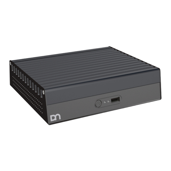
Overview Front View Figure 4-5: BEETLE M1350 Front View 1 Power Button 2 Power LED 3 USB 2.0 4 Activity LED Table 4-1: Front Panel Functions Designation Specification Power Button Single Press: On/Off Power LED The Power LED lights orange when the system has been shut down and is in power mode S5. -
Page 15: Back View
Overview Back View Figure 4-6: BEETLE M1350 Back View 1 LAN 2 COM 1 3 COM 2 4 USB 2.0 5 USB 3.1 6 Power in DC 24V 7 Cash drawer 8 USB type C PD 5/12/24V, DP 9 USB type C PD 5/12V, DP Copyright ©... -
Page 16: Top View
Risk of burns due to hot surface The device heats up during operation. Touching the hot surface can cause burns. Wait until the surface has cooled down. Wear protective gloves. Figure 4-7: BEETLE M1350 Top View 1 Heat Sink Copyright © 2022, Diebold Nixdorf 01750349439 B... -
Page 17: Inside View
Overview Inside View Figure 4-8: BEETLE M1350 Inside View 1 SODIMM socket 2 M.2 2280 socket 3 M.2 2280 socket Copyright © 2022, Diebold Nixdorf 01750349439 B... -
Page 18: Ac Power Adapter
1 DC power out 2 Power indicator 3 AC power adapter 4 AC power plug The external power supply is applicable for common line voltage. It automatically adjusts itself to the particular voltage. Copyright © 2022, Diebold Nixdorf 01750349439 B... -
Page 19: Connecting/Disconnecting Cables
Plug all data communication cables and fix them. • Connect the power supply unit via a DC cable with the BEETLE M1350. • Connect the power cord of the power supply unit with the surge protector sockets of the housing in- stallation. -
Page 20: Figure 5-2 4 Pin Power Plug
The lock is released. The metal of the plug is visible. Figure 5-2: 4 pin power plug • RJ plugs lock in place when plugged in. • To release a RJ plug push down the latch. Figure 5-3: RJ plug Copyright © 2022, Diebold Nixdorf 01750349439 B... -
Page 21: Figure 5-4 Usb Plug
Connecting/Disconnecting Cables • USB plugs that are not supplied with power do not latch in place when plugged in, and can be unplugged with a gentle pull. Figure 5-4: USB plug Copyright © 2022, Diebold Nixdorf 01750349439 B... -
Page 22: Storage Media
6 Storage Media Mass storage in the BEETLE M1350 is a double-slot Socket 3 (M-Key) for Type 2280 M.2 SSD card. • Solid State Disk (SSD) A solid state disk is a data storage drive that uses memory elements in place of a rotating disk to store data. -
Page 23: Replacement Of Solid State Disk (Ssd)
Figure 6-3: Removing the SSD 4. Insert the new SSD by pushing it into the slot in the direction indicated (1). 5. Put back and tighten the SSD screw (2) previ- ously removed. Figure 6-4: Replacing the SSD Copyright © 2022, Diebold Nixdorf 01750349439 B... -
Page 24: Replacement Of The Ram
Figure 6-5: Removing the RAM 6. When fitting in the new RAM, push it down- wards until it latches on (1) and a “click” sound is heard. Figure 6-6: Replacing the RAM Copyright © 2022, Diebold Nixdorf 01750349439 B... -
Page 25: Technical Security Device (Tse)
This "TSE" device is the DN solution of the Technical Security Device (crypto memory) which can be used in our POS systems / POS environment. Mounting the TSE module 1. Loosen the screw (1). Figure 7-1: Preparing the Beetle for the TSE module Copyright © 2022, Diebold Nixdorf 01750349439 B... -
Page 26: Figure 7-2 Unlocking The Cover
3. Flip open the cover (2). Figure 7-2: Unlocking the cover 4. Insert the SD card (3). 5. Close the cover (4). 6. Gently slide the cover to lock (5). Figure 7-3: Inserting the SD card Copyright © 2022, Diebold Nixdorf 01750349439 B... -
Page 27: Figure 7-4 Pre-Assembling The Tse Module
Technical Security Device (TSE) 7. Mount the bracket to the TSE module (1). Figure 7-4: Pre-assembling the TSE module 8. Insert the TSE module into the BEETLE (1). Figure 7-5: Inserting the TSE module Copyright © 2022, Diebold Nixdorf 01750349439 B... -
Page 28: Figure 7-6 Fixing The Tse Module
Technical Security Device (TSE) 9. Tighten the screw (1) to fix the TSE module. Figure 7-6: Fixing the TSE module Copyright © 2022, Diebold Nixdorf 01750349439 B... -
Page 29: Installation
8 Installation The Tools You Need Make sure you have the following tools available before beginning work on the BEETLE M1350: Phillips screwdrivers Torx screwdriver Torx TX10 Copyright © 2022, Diebold Nixdorf 01750349439 B... -
Page 30: Required Space
2 Wall installation Power Button downwards, 60 mm free space surrounding 3 Wall installation Power Button upwards, 60 mm free space surrounding 4 Wall installation Front Panel upwards, 60 mm free space surrounding Copyright © 2022, Diebold Nixdorf 01750349439 B... -
Page 31: Mounting Steps For Optional Wall Plate
Use only Diebold Nixdorf wall mount plate. 1. Use the recommended fasteners (not sup- plied) to attach the wall mount back plate onto the concrete wall. -
Page 32: Figure 8-4 Fixing The Device
Installation 4. Tighten the thumb screw on the bottom of the back plate to secure the device. Figure 8-4: Fixing the device Copyright © 2022, Diebold Nixdorf 01750349439 B... -
Page 33: Replacement Of The Lithium Battery
9 Replacement of the Lithium Battery NOTE The lithium battery may only be replaced by authorized personnel. Contact your service provider. Copyright © 2022, Diebold Nixdorf 01750349439 B... -
Page 34: Starting Up The System
10 Starting Up the System After installing the BEETLE M1350,switch on the system by using the Power button on the front panel. The system first performs an automatic self-test to test its basic functions. For example, you may see the following message (irrespective of processor type) on the monitor: DN „ID xx/xx Date“... -
Page 35: Post Code
0xF8 Recovery PPI is not available 0xF9 Recovery capsule is not found 0xFA Invalid recovery capsule DXE Phase 0xD0 CPU initialization error 0xD1 North Bridge initialization error 0xD2 South Bridge initialization error Copyright © 2022, Diebold Nixdorf 11-1 01750349439 B... - Page 36 Error loading Boot Option (LoadImage returned error) 0xDA Boot Option is failed (StartImage returned error) 0xDB Flash update is failed 0xDC Reset protocol is not available 0xDD DXE phase BMC self-test failure Copyright © 2022, Diebold Nixdorf 11-2 01750349439 B...
-
Page 37: Technical Data
12 Technical Data 12.1 12.1 BEETLE M1350 Table 12-1: Technical Data BEETLE M1350 Dimensions (width/height/depth) 182 x 52 x 162 mm Weight 1.5 kg + 0.2 kg mounting adapter Climatic Class DIN IEC 721-3-3 Class 3K3 up to 40º C Operating Temperature +5º... -
Page 38: Ac Power Adapter
Technical Data 12.2 12.2 AC Power Adapter Only use power supply units (PSU) released or approved by Diebold Nixdorf. The PSU has to comply with the following minimal requirements and common standards: Table 12-2: AC Power Adapter Rated input voltage 100-240VAC Rated input current 2.0A... -
Page 39: Total Available Power
12.3 Total Available Power The total power available for the external IO ports depends on the rating of AC power adapter used. Be- low is the Diebold Nixdorf’s approved AC power adapter for BEETLE M1350. Table 12-3: Total available power Part Number... -
Page 40: Certifications Of The Manufacturer
Modifications not authorized by the manufacturer may void user’s authority to operate this device. This class A digital apparatus complies with Canadian ICES-003. This device must accept any interference received, including interference that may cause undesired op- eration. Copyright © 2022, Diebold Nixdorf 13-1 01750349439 B... -
Page 41: Disposal
Electrical equipment should not be disposed of as normal municipal waste within the EU (crossed-out wheeled bin symbol). For information regarding the possible repurchase of used systems, please contact: contact.remarketing@dieboldnixdorf.com Copyright © 2022, Diebold Nixdorf 14-1 01750349439 B... - Page 42 DIEBOLD NIXDORF, Incorporated 50 Executive Pkwy | PO Box 2520 | Hudson, OH 44236 | USA © 2022 Diebold Nixdorf, Incorporated. All Rights Reserved.
Need help?
Do you have a question about the BEETLE M1350 and is the answer not in the manual?
Questions and answers