Table of Contents

Related Manuals for DIEBOLD NIXDORF DN 470 Series


Summary of Contents for DIEBOLD NIXDORF DN 470 Series
- Page 1 DN Series™ 470 Through-the-Wall Drive-up System Operator Manual 01750332558 D Public This document is property of Diebold Nixdorf and is intended for customer use. A written license agreement with Diebold Nixdorf is not required to use this material.
- Page 2 This document and the information contained herein are provided AS IS AND WITHOUT WARRANTY. In no event shall Diebold Nixdorf or its suppliers be liable for any special, indirect, or consequential dam- ages of any nature resulting from the use of information in this manual. The information contained in this document is subject to change without notice.
- Page 3 Table -1: Document History Material Number Date Remarks 01750332558 A 7/2019 Original edition 01750332558 B 6/2020 General update 01750332558 C 3/2021 Lockable/removable card box, access control 01750332558 D 9/2021 Display redesign and display cleaning Copyright © 2021, Diebold Nixdorf 01750332558 D...
-
Page 4: Table Of Contents
Accessing the Upper Chassis ....................5-7 5.2.1 Opening the Upper Chassis Rear Door .............. 5-7 5.2.2 Closing the Upper Chassis Rear Door ..............5-7 System and Device Touch Points ..................5-8 Accessing the Rear Service Display ..................5-14 Copyright © 2021, Diebold Nixdorf 01750332558 D... - Page 5 List of Figures Figure 3-1 DN Series™ 470 Through-the-Wall Drive-up System ...........3-1 Figure 3-2 Modules and Devices Mounted on the Fascia ............3-4 Figure 3-3 Fingerprint Scanner ....................3-6 Figure 3-4 User Guide Lights (UXL) ..................3-7 Copyright © 2021, Diebold Nixdorf 01750332558 D...
- Page 6 Figure 5-12 More Safe Touch Points - CMD-V6C ..............5-13 Figure 5-13 Additional Safe Touch Points With RM4H Recycling Module ........5-14 Figure 5-14 Accessing the Rear Service Display Inside of Upper Chassis Rear Door .....5-15 Copyright © 2021, Diebold Nixdorf 01750332558 D...
- Page 7 Media Capacity of the Retract/Reject Cassette .............3-35 Table 4-1 System Label Number For Specific Systems ............4-1 Table 6-1 System Label Number For Specific Systems ............6-2 Table 6-2 Suggested Cleaning Solutions ................6-6 Table A-1 Related Hardware Documentation .................A-1 Copyright © 2021, Diebold Nixdorf 01750332558 D...
- Page 8 System Conditions ....................B-1 Table B-3 Installation Specifications ..................B-2 Table B-4 Plinth Weights ......................B-2 Table B-5 Effective Power and Heat Output ................B-3 Table B-6 Mechanical Environmental Conditions ..............B-3 Table B-7 Environmental Conditions ..................B-3 Copyright © 2021, Diebold Nixdorf viii 01750332558 D...
-
Page 9: Introduction
Text following a bullet point represents an item in a list. ‚‘ Text in simple quotation marks relates to components/mounting parts which are in- cluded in the delivery package. Prerequisite that must be fulfilled before an action. Copyright © 2021, Diebold Nixdorf 01750332558 D... -
Page 10: Signs, Markings And Symbols
Table 1-2: Mandatory Signs Used Mandatory Signs Wear Wear Wear Wear ear protection eye protection foot protection hand protection Pull Observe main plug the manual Copyright © 2021, Diebold Nixdorf 01750332558 D... - Page 11 Introduction Prohibition signs Climb forbidden Copyright © 2021, Diebold Nixdorf 01750332558 D...
-
Page 12: Safety
WARNING Risk of impact Be careful not to injure your head when the control panel or rear door is opened. Move carefully when the control panel or the rear door is opened. Copyright © 2021, Diebold Nixdorf 01750332558 D... - Page 13 • Use only accessories and extension components that have been approved by . Nonobservance can result in damage to the system or violations of regulations concerning safety, radio interference and ergonomical requirements. Copyright © 2021, Diebold Nixdorf 01750332558 D...
- Page 14 Note that there are only safety extra-low voltage circuits (SELV circuits) if you want to feed voltage from an external source into prepared cables to install additional electronics (e. g. EMA connection). • To clean the system only use cleaning agents approved by Diebold Nixdorf (see chapter "Cleaning, Service and Maintenance" in the operating manual). •...
-
Page 15: System Description
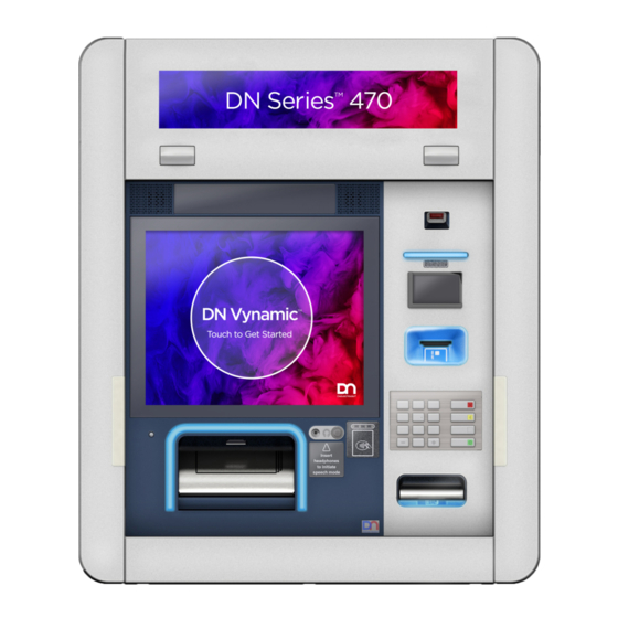
Supplies are replenished and service is performed from the rear of the system (see Figure 3-1). Figure 3-1: DN Series™ 470 Through-the-Wall Drive-up System Copyright © 2021, Diebold Nixdorf 01750332558 D... -
Page 16: Device Usage
The rear service display is used to perform maintenance. The operator uses the buttons on the external control unit with the operator interface to perform routine maintenance procedures. Copyright © 2021, Diebold Nixdorf 01750332558 D... -
Page 17: Fascia Components
(UXL) to guide the consumer through the transac- tion. The location of some devices and features can vary, depending on how they are installed on the system. A typical configuration of the fascia is shown in Figure 3-2. Copyright © 2021, Diebold Nixdorf 01750332558 D... -
Page 18: Figure 3-2 Modules And Devices Mounted On The Fascia
Consumer awareness mirror Consumer portrait/face camera Function keys Bar code reader Receipt printer slot Identification card scanner Fingerprint scanner Dip card reader Motorized card reader slot ActivEdge card reader slot Encrypting PIN pad (consumer keypad) Copyright © 2021, Diebold Nixdorf 01750332558 D... - Page 19 System Description Check deposit module slot NFC contactless card reader Coin dispenser slot Headphone jack (and volume control) Cash recycler or cash dispenser slot Task light Consumer display Speakers Copyright © 2021, Diebold Nixdorf 01750332558 D...
-
Page 20: Figure 3-3 Fingerprint Scanner
User guide lights guide the consumer through a transaction by calling attention to the next step in the transaction. These lights can display in colors and are used by the devices in Figure 3-4. Copyright © 2021, Diebold Nixdorf 01750332558 D... - Page 21 System Description Figure 3-4: User Guide Lights (UXL) Bar code reader Receipt printer slot Card reader Check deposit module Coin dispenser Cash recycling or cash dispenser module Copyright © 2021, Diebold Nixdorf 01750332558 D...
-
Page 22: Upper Chassis Components
(mutually ex- clusive combinations). Figure 3-5: Upper Chassis Devices Cash recycler or cash dispenser module upper unit Heater Coin dispenser Receipt printer Journal printer Check deposit module Motorized card reader Copyright © 2021, Diebold Nixdorf 01750332558 D... - Page 23 System Description Figure 3-6: More Upper Chassis Devices Lockable/removable card box Lockable card retain bin External control unit Rear service display Access control head module EM (electromechanical) Copyright © 2021, Diebold Nixdorf 01750332558 D...
- Page 24 System Description Cash Recycler - Upper Unit The cash recycler upper unit is located in the upper chassis directly above the cash recycler lower unit. Figure 3-7: Cash Recycler Upper Unit Copyright © 2021, Diebold Nixdorf 3-10 01750332558 D...
- Page 25 For more information, refer to the DN Series™ CMD-V6C Cash Dispenser Operating Manual (Order Number 01750342709). Figure 3-8: Cash Dispenser Upper Unit - CMD-V6C Copyright © 2021, Diebold Nixdorf 3-11 01750332558 D...
- Page 26 Checks can be inserted face up or face down with the short edge first for proper orientation. For more information, refer to the DN Series™ Check Deposit Module Operating Manual (Order Number 0175033061). Figure 3-9: Check Deposit Module Copyright © 2021, Diebold Nixdorf 3-12 01750332558 D...
- Page 27 Coin Dispenser The system may have a coin dispenser that dispenses coins in four different denominations. Figure 3-10: Coin Dispenser Coin dispenser Upper chassis System Coin slot Coin chute Fascia not shown for clarity. Copyright © 2021, Diebold Nixdorf 3-13 01750332558 D...
- Page 28 Open bin TP29 Journal Printer The TP29 journal printer can process paper rolls which have been coated on their upper side. Refer to the Journal Printer TP29 Operator Manual (Order Number 01750333697). Copyright © 2021, Diebold Nixdorf 3-14 01750332558 D...
- Page 29 TP31R (with Retract) Receipt Printer The TP31 receipt printer is a compact built-in printer with a terminal printing unit, integrated cutter and a presenter. Refer to the TP31R Receipt Printer Operating Manual (Order Number 01750333705). Copyright © 2021, Diebold Nixdorf 3-15 01750332558 D...
- Page 30 By turning the key in the door lock of the upper chassis door NOTE After unlocking the access control head module EM (electromechanical), you can turn the key in the door lock of the upper chassis door. Copyright © 2021, Diebold Nixdorf 3-16 01750332558 D...
- Page 31 The display also provides status information about the system. Refer to Section 5.4 for information about accessing the rear service display. Figure 3-12: System Door Open - Rear Service Display with Touch Screen Rear service display with touch screen with system door open Copyright © 2021, Diebold Nixdorf 3-17 01750332558 D...
- Page 32 The heater is mounted on top of the safe near the fascia. During cold weather, the heater helps maintain the operating temperature in the fascia area of the sys- tem. Figure 3-14: Heater Copyright © 2021, Diebold Nixdorf 3-18 01750332558 D...
-
Page 33: Table 3-2 Battery Option Leds
Service Button Pressing the wrench service button (Figure 3-15) initiates the service (maintenance) mode. Use T/SOP to perform system and module maintenance procedures. Copyright © 2021, Diebold Nixdorf 3-19 01750332558 D... -
Page 34: External Control Unit
3.3.1 External Control Unit Figure 3-15: External Control Unit - Overview On / Off LED Service button Main voltage LED Service LED Charging status LED (full) On / Off Button Status UPS LED Copyright © 2021, Diebold Nixdorf 3-20 01750332558 D... -
Page 35: Table 3-3 Functions Of The On/Off Button
If the LED is green, the system is operated via the normal mains supply. • If the LED lights up yellow, UPS operation is active. Battery Status Indicator The battery status indicator consists of two LEDs, which can indicate different battery statuses (see Figure 3-15). Copyright © 2021, Diebold Nixdorf 3-21 01750332558 D... - Page 36 FLASHING Main voltage switched on, system starts or shuts down Main voltage switched on, system ready for operation System runs in battery mode FLASHING System runs in battery mode, System shuts down Copyright © 2021, Diebold Nixdorf 3-22 01750332558 D...
-
Page 37: Safe Components
Recycling module, generation four horizontal (RM4H) cassette physical description (Section 3.4.12) • Safe lock (Section 3.4.13) • System switches (Section 3.4.14) • Alarm sensors (Section 3.4.15) • Seismic detectors (Section 3.4.16) • Third party alarms (Section 3.4.17) • Heat thermostat (Section 3.4.18) • Optional remote status indicator (Section 3.5) Copyright © 2021, Diebold Nixdorf 3-23 01750332558 D... - Page 38 System Description Figure 3-16: Devices Located in the Safe (RM4V) Safe lock (on the front of safe door) Recycling module lower unit Recycling module recycling cassettes Recycling module All-In cassette with multi-purpose bin Copyright © 2021, Diebold Nixdorf 3-24 01750332558 D...
- Page 39 System Description Figure 3-17: More Devices Located in the Safe Safe lock CMD-V6C cash dispenser lower module CMD-V6C cash dispenser supply cassettes CMD-V6C cash dispenser reject/retract cassette Copyright © 2021, Diebold Nixdorf 3-25 01750332558 D...
- Page 40 System Description Figure 3-18: Additional Devices Located in the Safe (RM4H) Safe Recycling module lower unit (horizontal) Recycling module recycling cassettes Copyright © 2021, Diebold Nixdorf 3-26 01750332558 D...
-
Page 41: Recycling Module, Generation Four Vertical (Rm4V) Lower Module Overview
RM4V sends the media to the All-In cassette. Refer to the Recycling Module, Generation Four Vertical (RM4V) Lower Module Operating Manual (Or- der Number 01750308109). Figure 3-19: Recycling Module, Generation Four Vertical (RM4V) Lower Module Copyright © 2021, Diebold Nixdorf 3-27 01750332558 D... -
Page 42: Recycling Module Rm4V, Recycling Cassettes
RM4V recycling module multiple times without having to reset a security feature. Figure 3-20: Convenience Recycling Cassette Lever Recycling convenience cassette The secure cassette can use security seals to indicate tampering. Copyright © 2021, Diebold Nixdorf 3-28 01750332558 D... -
Page 43: Recycling Module, Generation Four Vertical (Rm4V) All-In Cassettes
The All-In cassette can be a secure or convenience cassette. The primary compartment latches or un- locks like the recycling cassette (Figure 3-22). If currency is not taken by the customer, the currency is retracted into the multi purpose/retract bin on the back of the All-in cassette. Copyright © 2021, Diebold Nixdorf 3-29 01750332558 D... -
Page 44: Recycling Module Rm4V, Cassette Physical Description
Loaded with New Currency (3500 notes = 3.50 kg (7.72 pounds) 3.7 kg (8.3 pounds) Empty All-In cassette Table 3-6: Media Accommodated by the Cassette Dimension Minimum Maximum Recycling cassette Width 120 mm (4.72 inches) 182 mm (7.16 inches) Copyright © 2021, Diebold Nixdorf 3-30 01750332558 D... -
Page 45: Cmd-V6C Cash Dispenser Lower Module
For more information, refer to the DN Series™ CMD-V6C Cash Dispenser Operating Manual (Order Number 01750342709). Copyright © 2021, Diebold Nixdorf 3-31 01750332558 D... - Page 46 Supply cassette release lever CMD-V6C lower module Supply cassette release lever Supply cassette Locking/release lever for CMD-V6C lower module Supply cassette Supply cassette release lever Supply cassette Supply cassette release lever Supply cassette Reject/Retract cassette Copyright © 2021, Diebold Nixdorf 3-32 01750332558 D...
-
Page 47: Cmd-V6C Cash Dispenser Supply Cassettes
The front door of the supply cassette (Figure 3-24) opens with a simple lever and can be pushed shut to close. The cassette can be removed and reinserted into the CMD-V6C multiple times without having to reset a security feature. Figure 3-24: Supply Cassette Copyright © 2021, Diebold Nixdorf 3-33 01750332558 D... -
Page 48: Cmd-V6C Cash Dispenser Reject/Retract Cassette
Notes can be stored in the reject/retract cassette (Figure 3-25) which were recognized as counterfeit money, damaged, or were not removed by the customer during the cash-out procedure. Figure 3-25: CMD-V6C Cash Dispenser Reject/Retract Cassette Copyright © 2021, Diebold Nixdorf 3-34 01750332558 D... -
Page 49: Cmd-V6C Cassette Physical Description
420 mm total capacity approximately 3500 notes Table 3-12: Media Capacity of the Retract/Reject Cassette Size of media stack 110 notes for retract notes Capacity (new 20 Euro) 400 notes for reject notes Copyright © 2021, Diebold Nixdorf 3-35 01750332558 D... -
Page 50: Recycling Module Rm4H, Overview
Banknotes which can not be clearly identified as well as banknotes forgotten or not removed by the customer in a withdrawal, are placed in the reject/retract cassette or in the All In Box (configuration- dependent). • The input/output tray is protected by a shutter on the system side. Copyright © 2021, Diebold Nixdorf 3-36 01750332558 D... - Page 51 System Description Figure 3-26: RM4H Lower Unit All in Box Distributor module Safe compartment 4 through Recycling cassettes Copyright © 2021, Diebold Nixdorf 3-37 01750332558 D...
-
Page 52: Recycling Module Rm4H, Standard Cassette
The standard cassette is available in a basic, mid-range or high end configuration. Figure 3-27: Standard Cassette Basic/Midrange Cover LED display - Status display (midrange only) Location for rating/cassette label Handle Release lever Lock (optional) Copyright © 2021, Diebold Nixdorf 3-38 01750332558 D... -
Page 53: Recycling Module Rm4H, All-In Cassette
The All-in Cassette can be a secure or convenience cassette. The primary compartment latches or un- locks like the recycling cassettes. Figure 3-28: All-in Cassette Cover Location for rating /cassette label Handle Release lever of lock Lead seal possibility Copyright © 2021, Diebold Nixdorf 3-39 01750332558 D... -
Page 54: Recycling Module Rm4H, Cassette Physical Description
The weight of a completely filled cassette was ascertained using banknotes with a denomination of 50 euros. Refers to brand new banknotes Copyright © 2021, Diebold Nixdorf 3-40 01750332558 D... - Page 55 The weight of a completely filled cassette was ascertained using banknotes with a denomination of 50 Euros. Refers to brand new banknotes Copyright © 2021, Diebold Nixdorf 3-41 01750332558 D...
- Page 56 The storage capacity and weight of a completely filled cassette depends on the type, quality, nature and state of the banknotes. The weight of a completely filled cassette was ascertained using banknotes with a denomina- tion of 50 Euros. refers to brand new banknotes Copyright © 2021, Diebold Nixdorf 3-42 01750332558 D...
-
Page 57: Safe Lock
It serves to inform the operator of the current status of the system. In contrast to the remote status indicator - standard, the remote status indicator - Copyright © 2021, Diebold Nixdorf 3-43... - Page 58 In the case of display 1 (red), an additional continuous tone is generated. It can be deactivated using the Audio Reset key. However, the optical display will still output. Copyright © 2021, Diebold Nixdorf 3-44 01750332558 D...
- Page 59 Acoustic signal generator Continuous tone with Service Required. Follow the in- structions displayed on the monitor. If a error occurs in- form your service representative. Key - Audio Reset Switches the continuous tone off. Copyright © 2021, Diebold Nixdorf 3-45 01750332558 D...
-
Page 60: System Label
Table 4-1: System Label Number For Specific Systems Model Voltage MS (module state) Number 470V 110/120V 200/240V 470H 100/127V 200/240V 470C 100/127V 200/240V Figure 4-1: System Label Location System label location Copyright © 2021, Diebold Nixdorf 01750332558 D... - Page 61 System Label Figure 4-2: Example of a System Type Label System type Copyright © 2021, Diebold Nixdorf 01750332558 D...
- Page 62 To avoid risk of death, severe personal injury, or equipment damage, always follow the written maintenance procedures for the system and its individual modules. NOTE For maintenance procedures for the individual system modules, refer to the module oper- ating guides listed in Appendix A . Copyright © 2021, Diebold Nixdorf 01750332558 D...
-
Page 63: T/Sop
The "System LED" goes off as soon as the system has been shut down. Figure 5-1: Turning off the System NOTE! System shutdown may take a few sec- onds depending on operating system and run- ning transactions. Copyright © 2021, Diebold Nixdorf 01750332558 D... - Page 64 ü Make sure the power switch is on. Press the on/off button on the external con- trol unit (see chapter External control unit Overview. The ON/OFF LED lights up green. Figure 5-2: Switching off the System The system starts. Copyright © 2021, Diebold Nixdorf 01750332558 D...
- Page 65 The "System LED" goes off as soon as the system has been shut down. Figure 5-3: Turning off the System NOTE! System shutdown may take a few sec- onds depending on operating system and run- ning transactions. Copyright © 2021, Diebold Nixdorf 01750332558 D...
- Page 66 To power down specific modules, press the wrench button on the external control unit (External Control Unit Overview). Refer to T/SOP Device Overview screen to power down specific power rails (Figure 5-4). Refer to T/SOP to power down specific modules (Figure 5-5). Copyright © 2021, Diebold Nixdorf 01750332558 D...
- Page 67 Operation Figure 5-5: T/SOP Power Down Specific Modules Screen Copyright © 2021, Diebold Nixdorf 01750332558 D...
-
Page 68: Accessing The Upper Chassis
Release any mounting tray latches and push the mounting trays back into the system until they latch in place. Close and lock the upper chassis door (see Figure 5-7). Tug gently on the rear door after it is closed to make sure it is properly closed. Copyright © 2021, Diebold Nixdorf 01750332558 D... -
Page 69: System And Device Touch Points
Touch points are color coded green and include, but are not limited to, slide assembly release levers, module handles, device levers, knobs, etc. See Figure 5-8 through Figure 5-13 for examples of these touch points. Copyright © 2021, Diebold Nixdorf 01750332558 D... - Page 70 Operation Figure 5-8: Fascia Touch Points (MS02 consumer display) Consumer display handle Consumer display Coin chute latch pin (if present) Consumer display latch pin Copyright © 2021, Diebold Nixdorf 01750332558 D...
- Page 71 Operation Figure 5-9: Upper Chassis Touch Points Printer tray handle Printer tray release latch Coin tray handle Coin tray release latch Upper chassis rear door Copyright © 2021, Diebold Nixdorf 5-10 01750332558 D...
- Page 72 Operation Figure 5-10: More Upper Chassis Touch Points RM4 upper head unit or CMD-V6 cash dispenser release latch (RM4 shown) Check deposit module release latch Check deposit module handle Copyright © 2021, Diebold Nixdorf 5-11 01750332558 D...
- Page 73 Operation Figure 5-11: Safe Touch Points (RM4V) Recycling module cassettes Loopback transport release latch Recycling module lower unit release latch Recycling module lower unit handle Chest horizontal transport handle Copyright © 2021, Diebold Nixdorf 5-12 01750332558 D...
- Page 74 Operation Figure 5-12: More Safe Touch Points - CMD-V6C Reject/retract cassette handle Head transport release lever Supply cassette handle Supply cassette release latch CMD-V6C release latch Copyright © 2021, Diebold Nixdorf 5-13 01750332558 D...
-
Page 75: Accessing The Rear Service Display
ProBase/C and ProBase/J User Manual for more information. 5.4.1 5.4.1 Accessing Rear Service Display Inside of Upper Chassis Rear Door Perform the following steps to access the rear service display inside of the upper chassis rear door. Copyright © 2021, Diebold Nixdorf 5-14 01750332558 D... - Page 76 Close the upper chassis rear door (Section 5.2.2). Figure 5-14: Accessing the Rear Service Display Inside of Upper Chassis Rear Door Upper chassis Rear service display in operational posi- tion Upper chassis rear door in open position Copyright © 2021, Diebold Nixdorf 5-15 01750332558 D...
-
Page 77: Accessing Rear Service Display Through The Upper Chassis Rear Door
Close and lock the clear cover. Figure 5-15: Accessing Rear Service Display Through the Upper Chassis Rear Door Upper chassis Upper chassis rear door in closed position Rear service display clear cover Rear service display External control unit Copyright © 2021, Diebold Nixdorf 5-16 01750332558 D... -
Page 78: Pulling Out / Pushing In Cash Components
Pulling out / Pushing in the Upper Unit Unlock the upper unit by the release lever (1). Pull the upper unit out of the system by using the release lever (2). Figure 5-16: Pulling out the Upper Unit Copyright © 2021, Diebold Nixdorf 5-17 01750332558 D... -
Page 79: Pulling Out / Pushing In The Lower Unit
The release lever is marked green. Pull the release lever upwards (1). Pull the lower unit out of the system by using the release lever (2). Figure 5-18: Pulling out the Lower Unit Copyright © 2021, Diebold Nixdorf 5-18 01750332558 D... - Page 80 Operation Push the lower unit (1) into the system by using the release lever (2). Figure 5-19: Pushing in the Lower Unit Copyright © 2021, Diebold Nixdorf 5-19 01750332558 D...
-
Page 81: Accessing The Check Deposit Module
Push the check deposit module completely into the upper chassis until it latches securely in place. Close and lock the upper chassis rear door (refer to Section 5.2.2). Figure 5-20: Accessing the Check Deposit Module Upper chassis Check deposit module release latch Copyright © 2021, Diebold Nixdorf 5-20 01750332558 D... - Page 82 Operation System Check deposit module release handle Upper chassis rear door Direction to pull out check deposit mdoule Copyright © 2021, Diebold Nixdorf 5-21 01750332558 D...
-
Page 83: Accessing The Open Card Retain Bin And The Receipt Printer
Close and lock the upper chassis rear door (refer to Section 5.2.2). Figure 5-21: Accessing the Card Retain Bin and the Receipt Printer Receipt printer Printer tray in extended position Upper chassis rear door Printer tray release latch Copyright © 2021, Diebold Nixdorf 5-22 01750332558 D... - Page 84 Operation Open card retain bin Printer tray handle Copyright © 2021, Diebold Nixdorf 5-23 01750332558 D...
-
Page 85: Accessing The Safe
Push the coin dispenser tray back into the system until it latches securely in place. Close and lock the upper chassis rear door (refer to Section 5.2.2). Copyright © 2021, Diebold Nixdorf 5-24 01750332558 D... - Page 86 Operation Figure 5-22: Accessing the Coin Dispenser Upper chassis Mounting tray release latch Mounting tray handle Mounting tray Copyright © 2021, Diebold Nixdorf 5-25 01750332558 D...
-
Page 87: How To Read Bar Codes
Place the scanner light at the center of the bar code and wait for the scanner to pick up the data (Figure 5-23). You may have to move the scanner light up and down the bar code to get a reading. Figure 5-23: How to Read Bar Codes Bar code scanner Light Bar code Copyright © 2021, Diebold Nixdorf 5-26 01750332558 D... -
Page 88: Opening/Closing The Safe Door
The key-operated lock must then be set to the original key. It is not allowed to use the standard key several times or even permanently. Standard key This key is used to open the safe door with the factory-preset number combination lock. Copyright © 2021, Diebold Nixdorf 5-27 01750332558 D... - Page 89 Do not count the number of turns but the number of times the numbers appear below the opening index. The number combination lock is preset at the factory. Copyright © 2021, Diebold Nixdorf 5-28 01750332558 D...
- Page 90 '50' positioned exactly below the opening index. Then turn the dial of the number combination lock clockwise as far as possible. This releases the number combination lock. Open the key-operated lock cap (if installed). Copyright © 2021, Diebold Nixdorf 5-29 01750332558 D...
- Page 91 Insert the standard key into the lock. Turn the key clockwise as far as possible. Turn the locking/unlocking lever or wheel counterclockwise as far as possible. Open the safe door as far as possible. Copyright © 2021, Diebold Nixdorf 5-30 01750332558 D...
- Page 92 Close the cap of the lock (if installed). NOTE To change the number combination, you must turn the dial at least one full turn to the left and then four full turns to the right. Copyright © 2021, Diebold Nixdorf 5-31 01750332558 D...
- Page 93 Frontload only Close the system (see chapter "Opening/closing the doors") Close the front door or the standard/design door depending on the system used (refer to the sys- tem-specific operating manual, chapter "Basic operation"). Copyright © 2021, Diebold Nixdorf 5-32 01750332558 D...
-
Page 94: Customizing The Key And Number Combination Locks
- Always keep your keys in a safe place. - If you lose or misplace a key, always change the lock to fit a new key immediately, even if the original key (the previous key) is recovered. Copyright © 2021, Diebold Nixdorf 5-33 01750332558 D... - Page 95 Remove the key. The lock is now set to the new key. NOTE Before you close the door, check at least three times that the lock works correctly with the new key. Copyright © 2021, Diebold Nixdorf 5-34 01750332558 D...
- Page 96 The position of the service opening on the inside of the safe door depends on the safe type used. The illustration shows possible positions (1) or (2) of the service opening for the reset key. Copyright © 2021, Diebold Nixdorf 5-35 01750332558 D...
- Page 97 Test the new combination on the opening index at least 3 times with the safe door open. The new code is now set. NOTE Test the new combination on the opening index at least 3 times with the safe door open. Copyright © 2021, Diebold Nixdorf 5-36 01750332558 D...
-
Page 98: Opening/Closing The Safe Door (With Customized Lock)
The system comes with three original keys, which are used to open and close the safe door after instal- lation: 3 Original keys: These keys are used to open the safe door after system installation. Copyright © 2021, Diebold Nixdorf 5-37 01750332558 D... - Page 99 Turn the dial counterclockwise until the first number appears exactly below the opening index for the fourth time. Copyright © 2021, Diebold Nixdorf 5-38 01750332558 D...
- Page 100 Turn the dial counterclockwise until the third number appears exactly below the opening index for the second time. Then turn the dial clockwise as far as possi- ble. This releases the number combination lock. Copyright © 2021, Diebold Nixdorf 5-39 01750332558 D...
- Page 101 Operation Open the key-operated lock cap (if installed). Insert the original key into the lock. Turn the key clockwise as far as possible. Copyright © 2021, Diebold Nixdorf 5-40 01750332558 D...
- Page 102 Operation 10. Turn the locking/unlocking lever or wheel counterclockwise as far as possible. 11. Open the safe door as far as possible. Copyright © 2021, Diebold Nixdorf 5-41 01750332558 D...
- Page 103 Close the cap of the lock (if installed). NOTE To change the number combination, you must turn the dial at least one full turn to the left and then four full turns to the right. Copyright © 2021, Diebold Nixdorf 5-42 01750332558 D...
-
Page 104: Accessing The Upper Chassis - Access Control Head Module Em (Electromechanical)
EM (electromechanical) and upper chassis door key lock. NOTE To unlock the access control head module EM (electromechanical) you will need a 9V battery. The 9V battery is not included and must be obtained separately. Copyright © 2021, Diebold Nixdorf 5-43 01750332558 D... - Page 105 Figure 5-24: Connect Battery to Contacts Battery contacts Battery The access control head module EM (electromechanical) is unlocked. Remove the 9V battery from the battery contacts. Use the key to unlock the upper chassis door lock. Copyright © 2021, Diebold Nixdorf 5-44 01750332558 D...
-
Page 106: Accessing The Lockable/Removable Card Box
Push down on the spring loaded card box mounting bracket to access the lockable/removable card box (Figure 5-25). Figure 5-25: Lockable/Removable Card Box Location Receipt printer tray Spring loaded card box mounting bracket Lockable/removable card box Slide the card box toward the upper chassis rear door (Figure 5-26). Copyright © 2021, Diebold Nixdorf 5-45 01750332558 D... - Page 107 Close and lock the card box cover. The card box resets and the teeth in the card box slot retract. Reinstall the lockable/removable card box (Figure 5-27) onto the mounting bracket. Make sure the lock box audibly locks in place. Copyright © 2021, Diebold Nixdorf 5-46 01750332558 D...
-
Page 108: Accessing The Card Reader Lockable Card Retain Bin
Open bin Open the upper chassis rear door. Slide the receipt printer tray out of the system. Push down on the spring loaded bracket. Unlock and open the lockable retain bin (Figure 5-28). Copyright © 2021, Diebold Nixdorf 5-47 01750332558 D... -
Page 109: Ms02 Accessing The Consumer Display
This procedure is specifically for systems with a system type label number of MS 02. Check the system type label Section 4 to determine whether this procedure is appropriate for your system. Unlock the fascia. Release the left and right fascia latches that have orange stickers. Copyright © 2021, Diebold Nixdorf 5-48 01750332558 D... - Page 110 Extend the fascia on its slide assemblies. If the coin chute is present, release the latch pin and swing down the coin chute using the green touch point. Lift up the green display latch pin. Copyright © 2021, Diebold Nixdorf 5-49 01750332558 D...
- Page 111 Using the green display handle (not the latch pin), close the display. NOTE If the display latch pin is used to close the display, the display may not latch prop- erly. Verify that the display is closed and tightly latched Copyright © 2021, Diebold Nixdorf 5-50 01750332558 D...
-
Page 112: Maintenance
On systems not rated for weather exposure, use caution when cleaning exterior surfaces. DO NOT use more liquids than necessary. • Do not spray cleaners directly onto the system surface, spray the cleaner onto a cleaning cloth, then use the damp cloth to wipe the surface. Copyright © 2021, Diebold Nixdorf 01750332558 D... -
Page 113: Cleaning The Displays
Table 6-1: System Label Number For Specific Systems Model Voltage MS (module state) Number 470V 110/120V 200/240V 470H 100/127V 200/240V 470C 100/127V 200/240V Figure 6-1: System Label Location System label location Copyright © 2021, Diebold Nixdorf 01750332558 D... -
Page 114: Ms01 Consumer Display Cleaning
This procedure is specifically for systems with a system type label number of MS 02. Check the system type label Section 6.4.1 to determine whether this procedure is appropriate for your system. Unlock the fascia. Release the left and right fascia latches that have orange stickers. Copyright © 2021, Diebold Nixdorf 01750332558 D... - Page 115 Right fascia latch Extend the fascia on its slide assemblies. If the coin chute is present, swing down the coin chute using the green touch point. Lift up the green display latch pin. Copyright © 2021, Diebold Nixdorf 01750332558 D...
- Page 116 Softly clean the display and touch screen. CAUTION Be very careful when cleaning the touch screen. The back side can be easily scratched. Use a clean dry lint free fine fiber cloth to dry the surface. Copyright © 2021, Diebold Nixdorf 01750332558 D...
-
Page 117: Suggested Cleaning Solutions
6.4.4 Suggested Cleaning Solutions The following cleaning solutions may be used for cleaning the display, touch screen and privacy filter. Table 6-2: Suggested Cleaning Solutions Screen cleaning WN-260 01750035530 75% Alcohol Diluted soapy water Copyright © 2021, Diebold Nixdorf 01750332558 D... -
Page 118: A Related Documentation
DN Series™ Recycling Module (RM4H) Dispenser Operator Manual 01750306327 DN Series™ TP31R (with retract) Receipt Printer Operator Manual 01750333705 DN Series™ CMD-V6C Cash Dispenser Operator Manual 01750342709 DN Series™ Fingerprint Scanner Operator Manual 01750336258 Copyright © 2021, Diebold Nixdorf 01750332558 D... -
Page 119: B Technical Data
Country-specific safety plug connection (wall outlet) Fuse 20 A automatic circuit breaker 16 A automatic circuit breaker Degree of protec- IP X0 IP X0 tion according to EN 60529: [1] A heater would add 700W. Copyright © 2021, Diebold Nixdorf 01750332558 D... -
Page 120: Installation Specifications
DN OFA adj. plinth 155 – 240mm CEN 73 Kg 01750341166 DN OFA adj. plinth 115 – 160mm CEN 65 Kg 1750334215 Inst.-Sockel 25mm DN OFA-S CEN kpl. 27 Kg 1750334219 inst.Rahmen 25mm DN OFA-S UL kpl. 26.5 Kg Copyright © 2021, Diebold Nixdorf 01750332558 D... -
Page 121: Effective Power And Heat Output
-10 C to +40 C (14 to 104 F) 5 to 98 Noise Emissions Characteristic noise value ac- 45 dB(A) Idle mode 55 dB(A) Operation (typical oper- cording to ISO 9296 ating cycle) Copyright © 2021, Diebold Nixdorf 01750332558 D... -
Page 122: Compliance With Standards And Approvals
Voltage Directive 2014/35/EU. Certification for Data Transmission The certification number or CE mark of the data transmission module (if available) is attached directly to the DT card or to the housing of the system unit. Copyright © 2021, Diebold Nixdorf 01750332558 D... -
Page 123: Environmental Protection
Please observe the respective national regulations with regard to the disposal of elec- trical equipment. Electrical equipment should not be disposed of as normal municipal waste within the EU (crossed-out wheeled bin symbol). For information regarding the possible repurchase of used systems, please contact: contact.remarketing@dieboldnixdorf.com Copyright © 2021, Diebold Nixdorf 01750332558 D... - Page 124 Refers to a person who performs routine mainte- nance, such as replenishing supplies. An opera- tor may also perform procedures that help deter- mine the cause of certain problems, such as jammed paper in the printer. Copyright © 2021, Diebold Nixdorf 01750332558 D...
- Page 125 DIEBOLD NIXDORF 5995 Mayfair Road | North Canton, OH 44720 | United States © 2021 Diebold Nixdorf, Incorporated. All Rights Reserved.
Need help?
Do you have a question about the DN 470 Series and is the answer not in the manual?
Questions and answers