Advertisement
Quick Links
IMPORTANT
Carefully remove all the parts from the carton and
place them individually on a soft cloth to prevent
scratches or other damage.
Carefully and strictly follow these assembly instructions
to ensure a completed product as designed.
Do not use power tools above 8 volts to assemble.
Part List
Hardware List
Hex Wrench
1 pc.
Small
Hex Wrench
1 pc.
Tool(s) required for assembly: Phillips screwdriver, Level
home
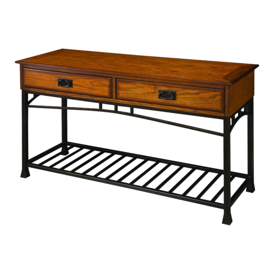
5050-22
Console Table
A.
Cabinet
1 pc.
C.
Side Frame
2 pcs.
styles Customer Service: www.homestylesfurniture.com,
servicedesk@homestylesfurniture.com,
M6x12
Head Cap Bolt
8 pcs. (+1 extra)
Flat Washer
8 pcs. (+1 extra)
888-680-7460
B.
Stretcher
2 pcs.
D.
Shelf
1 pc.
Spring Washer
8 pcs. (+1 extra)
M4x12
Wood Screw
6 pcs. (+1 extra)
Advertisement

Related Manuals for Home Styles 5050-22


Summary of Contents for Home Styles 5050-22
- Page 1 5050-22 Console Table IMPORTANT Carefully remove all the parts from the carton and place them individually on a soft cloth to prevent scratches or other damage. Carefully and strictly follow these assembly instructions to ensure a completed product as designed.
- Page 2 Assembly Instructions 2/4 IMPORTANT Ÿ Use a soft cloth between these parts and the floor. Ÿ Do not use power tools above 8 volts to assemble. Ÿ Do not tighten all the bolts until each part is properly assembled. Ÿ Keep Hex Wrench as the bolts may need to be tightened in the future.
- Page 3 Assembly Instructions 3/4 STEP 3 Place Cabinet (A) upside down Wood Screw on a soft cloth. Attach unit from Step 1 to Cabinet (A) with Wood Screws. Machine Screw Handle STEP 4 Turn unit over to its upright position. Remove handles on inside of drawers and attach to outside of drawers with machine screws. Slide drawers into position.
-
Page 4: Hardware List
Assembly Instructions 4/4 IMPORTANT Ÿ To help reduce the risk of the unit tipping over, the Tipover Restraint must be installed following these instructions exactly. STEP 5 Lock end Tie end Place unit at desired location. Drill a 3/8” hole in wall in-line with bottom of back center upright of unit. - Page 5 Digital images of the defective parts may be required. If the product was not purchased from an authorized retailer, home styles is under no obligation to provide replacement parts. Parts are not available for fully assembled items nor are parts available for sale. Replacements for missing or damaged parts may be requested via contact info below.
Need help?
Do you have a question about the 5050-22 and is the answer not in the manual?
Questions and answers