
Subscribe to Our Youtube Channel
Related Manuals for Beckhoff KL28 Series


Summary of Contents for Beckhoff KL28 Series
- Page 1 Documentation KL28xx HD Bus Terminals, digital output 24 V DC Version: 1.0.0 Date: 2016-12-15...
- Page 3 Product overview: digital output terminals Product overview: digital output terminals KL2808 [} 8] (8 digital outputs; 24 V DC, 0.5 A) KL2828 [} 11] (8 digital outputs; 24 V DC, 2 A) KL2809 [} 14] (16 digital outputs; 24 V DC, 0.5 A) KL2819 [} 20] (16 digital outputs; 24 V DC, 0.5 A, with diagnostics) KL2872 [} 17] (16 digital outputs;...
-
Page 4: Table Of Contents
Table of contents Table of contents 1 Product overview: digital output terminals..................... 3 2 Foreword .............................. 5 Notes on the documentation...................... 5 Safety instructions .......................... 6 Documentation Issue Status...................... 7 Non-reactive Bus Terminals ...................... 7 3 KL2808 - Introduction and technical data .................... 8 Introduction and pin assignment..................... -
Page 5: Foreword
The TwinCAT Technology is covered, including but not limited to the following patent applications and patents: EP0851348, US6167425 with corresponding applications or registrations in various other countries. ® EtherCAT is registered trademark and patented technology, licensed by Beckhoff Automation GmbH, Germany Copyright © Beckhoff Automation GmbH & Co. KG, Germany. -
Page 6: Safety Instructions
All the components are supplied in particular hardware and software configurations appropriate for the application. Modifications to hardware or software configurations other than those described in the documentation are not permitted, and nullify the liability of Beckhoff Automation GmbH & Co. KG. Personnel qualification This description is only intended for trained specialists in control, automation and drive engineering who are familiar with the applicable national standards. -
Page 7: Documentation Issue Status
Foreword Documentation Issue Status Version Comment 1.0.0 • First published Hardware versions The hardware versions (delivery state) can be taken from the serial number printed on the side of the terminal. Syntax of the serial number Structure of the serial number: WW YY FF HH WW - week of production (calendar week) YY - year of production FF - firmware version... -
Page 8: Kl2808 - Introduction And Technical Data
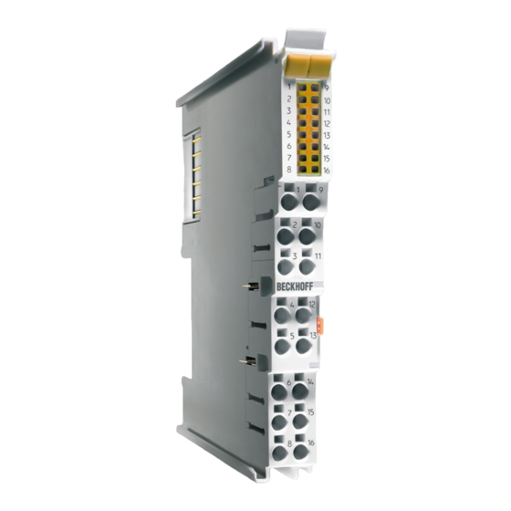
KL2808 - Introduction and technical data KL2808 - Introduction and technical data Introduction and pin assignment Fig. 1: KL2808 HD Bus Terminal, 8-channel digital output 24 V DC, 0.5 A The KL2808 digital output terminal connects the binary control signals from the automation device on to the actuators at the process level with electrical isolation. - Page 9 KL2808 - Introduction and technical data KL2808 – pin assignment Terminal point Description Name Output 1 Output 1 Output 2 Output 2 Output 3 Output 3 Output 4 Output 4 Output 5 Output 5 Output 6 Output 6 Output 7 Output 7 Output 8 Output 8...
-
Page 10: Technical Data
KL2808 - Introduction and technical data Technical data Technical data KL2808 Connection technology 2-wire Number of Outputs Rated load voltage 24 V DC (-15 %/+20 %) Current consumpt. K-bus typ. 20 mA Load type ohmic, inductive, lamp load Max. output current 0.5 A (short-circuit-proof) per channel Short circuit current <... -
Page 11: Kl2828 - Introduction And Technical Data
KL2828 - Introduction and technical data KL2828 - Introduction and technical data Introduction and pin assignment Fig. 2: KL2828 HD Bus Terminal, 8-channel digital output 24 V DC, 2 A The 8-channel KL2828 digital output terminal connects the binary control signals from the electrically isolated automation device on to the actuators at the process level. - Page 12 KL2828 - Introduction and technical data KL2828 - pin assignment Terminal point Description Name Output 1 Output 1 Output 2 Output 2 Output 3 Output 3 Output 4 Output 4 Output 5 Output 5 Output 6 Output 6 Output 7 Output 7 Output 8 Output 8...
-
Page 13: Technical Data
KL2828 - Introduction and technical data Technical data Technical data KL2828 Connection technology 2 wire Number of outputs Rated load voltage 24 V (-15% / +20%) Current consumption K-bus typ. 18 mA Load type ohmic, inductive, capacitive Max. output current 2 A per channel ( ∑ 10 A) Short circuit current <... -
Page 14: Kl2809, Kl2889 - Introduction And Technical Data
KL2809, KL2889 - Introduction and technical data KL2809, KL2889 - Introduction and technical data Introduction and pin assignment Fig. 3: KL2809 Fig. 4: KL2889 Version: 1.0.0 KL28xx... - Page 15 KL2809, KL2889 - Introduction and technical data HD Bus Terminals, 16-channel digital output 24 V DC, 0.5 A The KL2809 digital output terminal connects the binary control signals from the automation device on to the actuators at the process level with electrical isolation. The KL2809 is protected against polarity reversal and processes load currents with outputs protected against overload and short-circuit.
-
Page 16: Technical Data
KL2809, KL2889 - Introduction and technical data Technical data Technical data KL2809 KL2889 Connection technology 1-wire Number of Outputs Rated load voltage 24 V DC (-15 %/+20 %) Current consumpt. K-bus typ. 35 mA typ. 45 mA Load type ohmic, inductive, lamp load Max. -
Page 17: Kl2872, Kl2872-0010 - Introduction And Technical Data
KL2872, KL2872-0010 - Introduction and technical data KL2872, KL2872-0010 - Introduction and technical data Introduction and pin assignment Fig. 5: KL2872 KL28xx Version: 1.0.0... -
Page 18: Fig. 6 Kl2872-0010
KL2872, KL2872-0010 - Introduction and technical data Fig. 6: KL2872-0010 Bus Terminals, 16-channel digital output 24 V DC, 0.5 A, flat-ribbon cable connection The KL2872-00x0 digital output terminals offers a very compact design with its 16 channels. It is thus ideally suited for multi-pin connector valve terminals. -
Page 19: Fig. 7 Dimensions Of The 20-Pin Contact Strip Of The Terminal And The Matching Spring Contact Strip; For Connections See Contact Assignment
KL2872, KL2872-0010 - Introduction and technical data Contact pin strip Fig. 7: Dimensions of the 20-pin contact strip of the terminal and the matching spring contact strip; for connections see Contact assignment Technical data Technical data KL2872 KL2872-0010 Connection technology flat-ribbon cable Number of Outputs Rated load voltage 24 V DC (-15 %/+20 %) -
Page 20: Kl2819 - Introduction And Technical Data
KL2819 - Introduction and technical data KL2819 - Introduction and technical data Introduction and pin assignment Fig. 8: KL2819 HD Bus Terminal, 16-channel digital output 24 V DC, 0.5 A, with diagnostics The KL2819 Bus Terminal has 16 digital output channels for the switching of 24 V loads up to 0.5 A. The integrated diagnostics can be evaluated by the controller and indicated by the LEDs. - Page 21 KL2819 - Introduction and technical data KL2819 – pin assignment Terminal point Description Name Output 1 Output 1 Output 2 Output 2 Output 3 Output 3 Output 4 Output 4 Output 5 Output 5 Output 6 Output 6 Output 7 Output 7 Output 8 Output 8...
-
Page 22: Technical Data
EN 61000-6-2/EN 61000-6-4 Installation pos. Variable, see section "Installation positions" [} 29] of chapter "Mounting and wiring" [} 23] Protect. class IP20 Approvals Continuing documentation A detailed description can be found within the documentation of KL2819 Bus Terminal: http://www.beckhoff.de/english/download/busterm.htm Version: 1.0.0 KL28xx... -
Page 23: Mounting And Wiring
Mounting and wiring Mounting and wiring Installation on mounting rails Risk of electric shock and damage of device! Bring the bus terminal system into a safe, powered down state before starting installation, disassembly or wiring of the Bus Terminals! WARNING Assembly Fig. 9: Attaching on mounting rail The Bus Coupler and Bus Terminals are attached to commercially available 35 mm mounting rails (DIN rails... -
Page 24: Fig. 10 Disassembling Of Terminal
Mounting and wiring Disassembly Fig. 10: Disassembling of terminal Each terminal is secured by a lock on the mounting rail, which must be released for disassembly: 1. Pull the terminal by its orange-colored lugs approximately 1 cm away from the mounting rail. In doing so for this terminal the mounting rail lock is released automatically and you can pull the terminal out of the bus terminal block easily without excessive force. -
Page 25: Installation Instructions For Enhanced Mechanical Load Capacity
Mounting and wiring Fig. 11: Power contact on left side Possible damage of the device Note that, for reasons of electromagnetic compatibility, the PE contacts are capacitatively coupled to the mounting rail. This may lead to incorrect results during insulation testing or Attention to damage on the terminal (e.g. -
Page 26: Connection System
Mounting and wiring Additional installation instructions For terminals with enhanced mechanical load capacity, the following additional installation instructions apply: • The enhanced mechanical load capacity is valid for all permissible installation positions • Use a mounting rail according to EN 60715 TH35-15 •... -
Page 27: Fig. 13 Pluggable Wiring
Mounting and wiring Pluggable wiring Fig. 13: Pluggable wiring The terminals of KSxxxx and ESxxxx series feature a pluggable connection level. The assembly and wiring procedure for the KS series is the same as for the KLxxxx and ELxxxx series. The KS/ES series terminals enable the complete wiring to be removed as a plug connector from the top of the housing for servicing. -
Page 28: Fig. 15 Mounting A Cable On A Terminal Connection
Mounting and wiring Wiring Terminals for standard wiring ELxxxx / KLxxxx and terminals for steady wiring ESxxxx / KSxxxx Fig. 15: Mounting a cable on a terminal connection Up to eight connections enable the connection of solid or finely stranded cables to the Bus Terminals. The terminals are implemented in spring force technology. -
Page 29: Installation Positions
Mounting and wiring Shielding Shielding Analog sensors and actors should always be connected with shielded, twisted paired wires. Note Installation positions Constraints regarding installation position and operating temperature range Please refer to the technical data for a terminal to ascertain whether any restrictions re- garding the installation position and/or the operating temperature range have been speci- Attention fied. -
Page 30: Fig. 17 Other Installation Positions
Mounting and wiring Other installation positions All other installation positions are characterized by different spatial arrangement of the mounting rail - see Fig “Other installation positions”. The minimum distances to ambient specified above also apply to these installation positions. Fig. 17: Other installation positions Version: 1.0.0 KL28xx... -
Page 31: Atex - Special Conditions
Mounting and wiring ATEX - Special conditions Observe the special conditions for the intended use of Beckhoff fieldbus components in potentially explosive areas (directive 94/9/EU)! • The certified components are to be installed in a suitable housing that guarantees a... -
Page 32: Atex Documentation
Mounting and wiring Marking The Beckhoff fieldbus components certified for potentially explosive areas bear one of the following markings: II 3 G Ex nA II T4 KEMA 10ATEX0075 X Ta: 0 - 55°C II 3 G Ex nA nC IIC T4 KEMA 10ATEX0075 X Ta: 0 - 55°C... -
Page 33: Appendix
Beckhoff's branch offices and representatives Please contact your Beckhoff branch office or representative for local support and service on Beckhoff products! The addresses of Beckhoff's branch offices and representatives round the world can be found on her internet pages: http://www.beckhoff.com You will also find further documentation for Beckhoff components there. - Page 34 List of illustrations List of illustrations Fig. 1 KL2808 ............................Fig. 2 KL2828 ............................Fig. 3 KL2809 ............................Fig. 4 KL2889 ............................Fig. 5 KL2872 ............................Fig. 6 KL2872-0010 ..........................Fig. 7 Dimensions of the 20-pin contact strip of the terminal and the matching spring contact strip; for connections see Contact assignment..................
Need help?
Do you have a question about the KL28 Series and is the answer not in the manual?
Questions and answers