
Related Manuals for Beckhoff KL3012


Summarization of Contents
1 Foreword
1.1 Notes on the documentation
Intended audience, disclaimer, trademarks, and patent information.
1.2 Safety instructions
Safety regulations, exclusion of liability, personnel qualification, and hazard symbols.
1.3 Documentation issue status
Version history, firmware/hardware versions, and serial number syntax.
2 Product overview
2.1 KL301x - Introduction
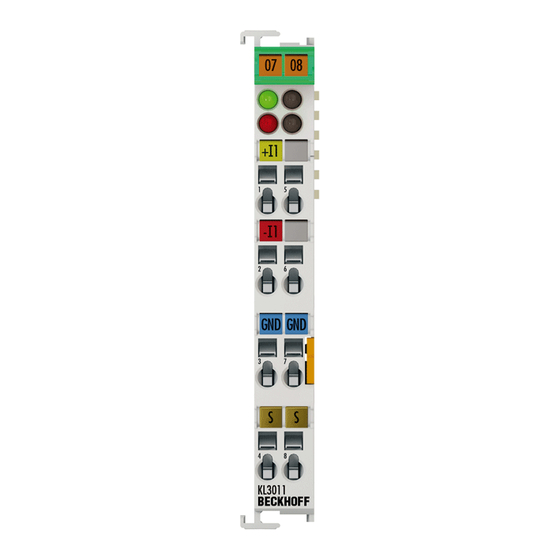
Details on KL3011/KL3012 terminals, connection diagrams, and LED descriptions.
2.2 KL302x - Introduction
Details on KL3021/KL3022 terminals, connection diagrams, and LED descriptions.
2.3 KL301x, KL302x - Technical data
Comprehensive technical specifications including electrical, environmental, and approval details.
2.4 Basic function principles
Explanation of analog input, LED functions, process data output, and calculation equations.
3 Mounting and wiring
3.1 Instructions for ESD protection
Guidelines to prevent electrostatic discharge damage during device handling.
3.2 Installation on mounting rails
Procedures for attaching bus couplers and terminals to 35 mm mounting rails.
3.3 Installation instructions for enhanced mechanical load capacity
Additional installation requirements for terminals with enhanced mechanical load capacity.
3.4 Connection
3.4.1 Connection system
Overview of different connection options for Bus Terminal systems.
3.4.2 Wiring
Instructions for connecting cables to terminals using spring force technology.
3.4.3 Shielding
Recommendations for connecting shielded, twisted paired wires for encoders and sensors.
3.5 KL301x - Connection and LED description
Details on terminal connections and LED functions for KL301x series.
3.6 KL302x – Connection and LED description
Details on terminal connections and LED functions for KL302x series.
3.7 ATEX - Special conditions (standard temperature range)
Special conditions for using Beckhoff components in potentially explosive areas (standard temp).
3.8 ATEX - Special conditions (extended temperature range)
Special conditions for using Beckhoff components in potentially explosive areas (extended temp).
3.9 ATEX Documentation
Notes about operating Beckhoff terminal systems in potentially explosive areas (ATEX).
4 Configuration Software KS2000
4.1 KS2000 - Introduction
Overview of KS2000 software for configuration, commissioning, and parameterization.
4.2 Sample program for KL register communication via EtherCAT on KL3314 exemplary
Demonstrates KL register communication using a sample program with EtherCAT.
5 Access from the user program
5.1 Terminal configuration
How terminals are configured and parameterized via internal register structure in Bus Couplers.
5.2 Mapping in the Bus Coupler
Information on how terminals map themselves in the Bus Coupler based on parameters.
5.2.1 KL3011 and KL3021
Default mapping configurations for KL3011 and KL3021 with various coupler types.
5.2.2 KL3012 and KL3022
Default mapping configurations for KL3012 and KL3022 with various coupler types.
5.3 Register overview
List and description of registers available for each terminal channel.
5.4 Register description
Detailed explanation of terminal registers, including RAM, ROM, SEEROM, and data types.
5.5 Control and status byte
Explanation of control and status bytes for terminal operation and data exchange.
5.5.1 Process data exchange
Details on control and status bytes used in process data exchange.
5.5.2 Register communication
How to access registers via process data exchange and register mode control byte.
5.6 Examples of Register Communication
Examples of register communication procedures and their explanations.
5.6.1 Example 1: reading the firmware version from Register 9
Step-by-step guide to read firmware version using Register 9.
5.6.2 Example 2: Writing to an user register
Guide to writing to user registers, including code word activation and checking.
6 Appendix
6.1 Support and Service
Information on Beckhoff support, branch offices, headquarters, and service options.
Need help?
Do you have a question about the KL3012 and is the answer not in the manual?
Questions and answers