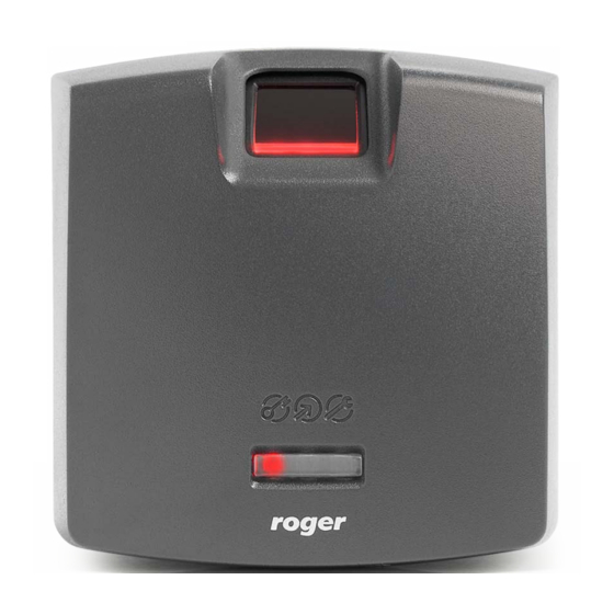
Roger RFT1000 User Manual
Reader in racs 5
Hide thumbs
Also See for RFT1000:
- User manual (20 pages) ,
- Integration manual (16 pages) ,
- Quick start manual (2 pages)
Table of Contents
Advertisement
Quick Links
© 2016 ROGER sp. z o.o. sp.k. All rights reserved. This document is subject to the Terms of Use in their current version published at
the
www.roger.pl
website of the Roger sp. z o.o. sp.k. company (hereinafter referred to as ROGER).
Roger Access Control System
RFT1000 reader in RACS 5
User Manual
Firmware version: 1.4.4 or newer
Hardware version: 1.1
Document version: Rev. E
Advertisement
Table of Contents

Subscribe to Our Youtube Channel
Summary of Contents for Roger RFT1000
- Page 1 Hardware version: 1.1 Document version: Rev. E © 2016 ROGER sp. z o.o. sp.k. All rights reserved. This document is subject to the Terms of Use in their current version published at www.roger.pl website of the Roger sp. z o.o. sp.k. company (hereinafter referred to as ROGER).
-
Page 2: Table Of Contents
4.1.1 Configuration of communication parameters ..............8 4.1.2 Recognition modes ......................9 4.1.4 Inputs ........................... 9 4.2 Communication with RFT1000 (VISO) ................10 4.3 User enrolment in 1:N mode ..................... 10 4.4 User enrolment in 1:1 mode ..................... 10 4.4.1 Master Authorisation ....................11 4.5 User identification ...................... -
Page 3: Introduction
RFT1000 readers in RACS 5 access control system. Additional information on RACS 5 configuration can be found in the Application Note AN006 which is available at www.roger.pl. The application of RFT1000 reader in RACS 4 and third party systems is described in dedicated documents which are also available at www.roger.pl. -
Page 4: Installation
RFT1000 in RACS 5 User Manual.doc 2021-09-14 Fig. 1 The example of RFT1000 operation with MC16-PAC-1-KIT 3. I NSTALLATION 3.1 Terminals and connection diagram 4/13... - Page 5 RFT1000 in RACS 5 User Manual.doc 2021-09-14 Fig. 2 RFT1000 terminals Table 2. RFT1000 terminals Terminal Description Positive power supply contact, 12VDC Negative power supply contact reference potential RS485 communication bus and input lines Tamper switch, 24V/50mA Tamper switch, 24V/50mA...
-
Page 6: Led Indicators
3.4 Inputs RFT1000 reader is equipped with two (IN1, IN2) inputs which can be configured as NO/NC with RogerVDM software. Inputs can be assigned with functions using RogerVDM software and VISO... -
Page 7: Wall Mounting
Damages to scanner surface are beyond the scope of warranty. · RFT1000 reader should be installed in shaded and dry place, far from heat and moisture. It is necessary to avoid dust and abrupt temperature changes. The reader cannot be installed in places exposed to direct sunlight. -
Page 8: Configuration
4. In the opened window (fig.6) select RFT1000 v1.0 device, firmware v1.4 and Ethernet communication channel. 5. IP address and port of RFT1000 reader is automatically detected by RogerVDM software if the reader and PC with RogerVDM are in the same subnet and communication between them is not blocked. -
Page 9: Recognition Modes
Input lines , which can be displayed by means of the command Configuration in the top menu of RogerVDM software. When RFT1000 reader is installed in RACS 5 system only the function [5]: Card Reader Mode is applicable. Other available functions are used beyond RACS systems. In general, input functions of Roger devices depending on assigned functions can be momentary or constant type. -
Page 10: Communication With Rft1000 (Viso)
RogerSVC services, controller detection and door creating in VISO software. All these steps are explained in the document AN006 RACS 5 Quick Start Guide. RFT1000 after connection to MC16 controller must be detected on RS485 bus. If the readers is operated in 1:N mode then it must be additionally configured in VISO software as follows: 1. -
Page 11: Master Authorisation
6. Upload settings to controller. Note: In 1:1 mode do not define RFT1000 reader in VISO software and do not assign users with any fingerprint templates in VISO software. Table 5. Maximal number of fingerprint templates on Mifare cards Card Max. -
Page 12: Full Memory Reset
3. Select the command Tools in the top menu of RogerVDM software and then select Update Firmware. 4. In the opened window select RFT1000 firmware file (*.frg extension) by means of the button Select file 5. Select the button Update in order to upload the firmware to RFT1000 6. -
Page 13: Ordering Information
RFT1000 in RACS 5 User Manual.doc 2021-09-14 5. O RDERING INFORMATION Table 7 Ordering information Product Description RFT1000 Fingerprint and Mifare Ultralight/Classic proximity card reader. MFC-2 13.56 MHz Mifare Classic ISO size thin PVC card, 1k bytes memory. MFC-3 13.56 MHz Mifare Classic ISO size thin PVC card, 4k bytes memory.


Need help?
Do you have a question about the RFT1000 and is the answer not in the manual?
Questions and answers