Emerson PACSystems IC695CPE400 Quick Start Manual
64mb rackless cpu
Hide thumbs
Also See for PACSystems IC695CPE400:
- Quick start manual (33 pages) ,
- Quick start manual (33 pages)
Table of Contents
Advertisement
Quick Links
Advertisement
Table of Contents

Related Manuals for Emerson PACSystems IC695CPE400


Summary of Contents for Emerson PACSystems IC695CPE400
- Page 1 ™ PACSystems IC695CPE400 64MB Rackless CPU GFK-3002G May 2021...
-
Page 2: Table Of Contents
Contents Contents ....................i Front Panel Description ................1 User Features ..................2 Switches ....................6 Displays and Indicators (LEDs) ..............7 OLED Display ....................7 Front-Panel Ethernet Ports ................11 Serial COM Port .................... 12 Video Display Port ..................12 Field Agent Port .................... -
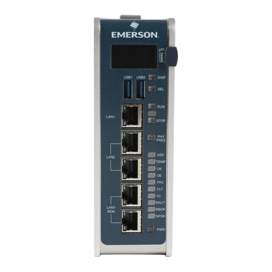
Page 3: Front Panel Description
Front Panel Description Figure 1: Display, Lights, and Connectors on the CPE400 IC695CPE400 Rackless CPU Quick Start Guide GFK-3002G... -
Page 4: User Features
User Features The PACSystems™ RX3i CPE400, part of Emerson’s Industrial Internet Control System, is the industry’s first outcome optimizing controller. It augments real-time deterministic control with Field Agent technology, delivering near real time advice through market analysis, fleet and enterprise data, or asset/process knowledge to optimize the outcomes that today’s businesses require. - Page 5 edge apps. Running the Field Agent concurrently with the real-time control applications allows the CPE400 to rapidly leverage external data. External monitoring may be used to analyze and optimize entire business operations. The analysis can then be used to dynamically adjust real-time industrial controls to align with changing business objectives in today’s Industrial Internet age.
- Page 6 Media Redundancy Protocol (MRP) allows the CPE400 to participate in a ▪ PROFINET I/O network with MRP ring technology. This eliminates the I/O network as a single point of failure. The CPE400 may be used as either a Media Redundancy Manager or Media Redundancy Client. Effective with firmware release 9.30, the CPE400 supports Hot Standby ▪...
- Page 7 Effective with firmware release 10.15, the CPE400 supports Sequence of ▪ Events recording through the Embedded PROFINET Controller when used with up to five IC695PNS101 Advanced PROFINET Scanner modules and a pair of dedicated C program blocks designed to configure and collect SoE records and provide diagnostics.
-
Page 8: Switches
▪ Switches All user-accessible switches are provided as pushbuttons on the front panel as described below. Pushbutton Function DISP Permits user to navigate menus in the OLED display. Permits user to select the menu item on the OLED display. Activates OLED Menu to select RUN/Enabled or RUN/Disabled Mode for the embedded PLC. -
Page 9: Displays And Indicators (Leds)
Displays and Indicators (LEDs) OLED Display The monochrome organic light-emitting diode (OLED) display is used to display CPE400 system menus. It interacts with the DISP pushbutton, which jogs the cursor from one menu item to the next, and with the SEL pushbutton, which activates the currently indicated menu item for further action. - Page 10 Status Indicators (LEDs) LED State Operating State On Green PLC is in RUN mode. MODE PLC is in STOP mode. Blinking CPU is updating an internal programmable in unison hardware device. On Green TPM Physical Presence (not functional). PRES On Green Activity detected on Solid State Disk. No activity detected on Solid State Disk.
- Page 11 LED State Operating State On Green Output scan is enabled. Output scan is disabled. One or more Overrides active in I/O Reference Yellow Table(s). No Overrides active in any I/O Reference Table. On Red PLC is in STOP/Faulted mode: a fatal fault has occurred.
- Page 12 Front Ethernet Indicators (LAN1, LAN2, LAN3 RJ45 Built-in LEDs) LED State Operating State Link The corresponding link has been established. Status Green (upper) Blinking Traffic is detected at the corresponding port. Green No connection established at corresponding port. Link Corresponding data speed is 1 Gbps or 100 Mbps. Speed Green (lower)
-
Page 13: Front-Panel Ethernet Ports
Front-Panel Ethernet Ports LAN1 connects to the uppermost RJ45 connector. It is not switched. LAN2 connects to the middle two RJ45 connectors. These two ports are switched internally. LAN3 connects to the two lower RJ45 connectors. These two ports are switched internally. -
Page 14: Serial Com Port
Serial COM Port Figure 2: Underside Ports & The RJ45 port marked Serial COM is Connections located on the underside of the CPE400, as shown in Figure 2. Effective with firmware release 9.40, the CPE400 supports the serial port. This port supports Serial IO protocol. -
Page 15: Energy Pack Connector
Reference Manual, GFK-2222 or later. For more detailed information regarding Field Agent, refer to the Field Agent User’s Guide, GFK-2993. The FAOK LED, located on the front panel, indicates the status of the Field Agent interface. Energy Pack Connector The CPE400 compatible Energy Pack, IC695ACC403, is supplied with a purpose-built cable, IC695CBL003, which installs in the 24 VDC In and Energy Pack Control &... -
Page 16: Hardware Installation
As the consignee, it is your responsibility to register a claim with the carrier for damage incurred during shipment. Emerson will fully cooperate with you, however, should such action be necessary. After unpacking the equipment, record all serial numbers. Serial numbers are required if you should need to contact Customer Care during the warranty period. - Page 17 For installation to standards, refer to the Installation and Maintenance Requirements document, GFK-3004. Note the thermal requirements for mounting the equipment (Figure 3). Mount on the DIN rail per Figure 1. Incline the unit so that the upper hooks of the DIN rail adaptor engage with the upper edge of the DIN rail.
- Page 18 Figure 4: Mounting on DIN Figure 3: Thermal Spacing Requirements Rail adjacent device above Air flow max. 70°C 25mm 50mm 50mm Figure 5: Dismounting from DIN Rail Air flow adjacent device below IC695CPE400 Rackless CPU Quick Start Guide GFK-3002G...
- Page 19 If using the panel-mount adaptor, two options are available: mount using two screws (Figure 6) or, for more secure mounting, mount using four screws (Figure 7). Figure 6: Two-Screw Panel Mount Figure 7: Four-Screw Panel Mount IC695CPE400 Rackless CPU Quick Start Guide GFK-3002G...
-
Page 20: Installation In Hazardous Areas
Installation in Hazardous Areas Refer to the Installation and Maintenance Requirements document, GFK- 3004. Connect to Power Supply Figure 8: 24 VDC Power The 24Vdc power input connector is located Input Connector on the underside of the CPE400, as shown in Figure 8. - Page 21 The user-supplied SELV power supply must Figure 9: 24 VDC Power supply voltage in the range of 18Vdc to Input Module Connector 30Vdc. Once the power supply cable (or compatible Energy Pack ACC403) has been attached to the CPE400 and the power supply has been turned on, the unit will start booting.
- Page 22 CAUTION EQUIPMENT REPAIR REQUIRED – Internal components must be repaired at the factory; they are not field replaceable. Contact the support team at the link provided at the end of this document. Overcurrent protection The function protects the internal circuitry from overcurrent conditions before serious damage can occur, such as overheating of the equipment.
-
Page 23: Module Start-Up
Module Start-up You Will Need: This PACSystems Rackless RX3i CPU. ▪ A compatible SELV 24Vdc, 48W power supply (72W if Energy Pack ▪ attached). (Optionally) A compatible Energy Pack, IC695ACC403, and corresponding ▪ cable. If no Energy Pack is to be attached, use the power supply cable described in ▪... -
Page 24: Basic Start-Up Steps
Basic Start-up Steps For startup and configuration of the CPE400, complete the following steps. For full details on CPE400 operation, refer to the PACSystems RX3i and CPU Reference Manual, GFK-2222. 1. Mount the CPE400, as described in section Installation and per the Installation and Maintenance Requirements document, GFK-3004. -
Page 25: Configuration
Note: In the event of loss of power with the ACC403 Energy Pack connected and charged up, the CPE400 remains on for 4 seconds to backup user memory into its non-volatile memory. Configuration To configure, the CPE400, connect the computer running the PME programming software to any of the front-panel Ethernet ports. -
Page 26: Start The Embedded Field Agent (Efa)
details, refer to the PACSystems RX3i PROFINET IO Controller User Manual, GFK-2571. Figure 10: PME Navigator Showing PROFINET Node on LAN2 Start the Embedded Field Agent (EFA) After providing the CPE400 with power, the Embedded Field Agent (EFA) application will begin to boot. The FAOK LED will start blinking to indicate when the EFA has booted and is ready for user logins. -
Page 27: Log Into The Web Console
Log into the Web Console 1. Connect a computer to the EFA’s IICS Cloud Port or EFA Port. 2. Configure the computer’s network adapter to be an address on the Field Agent network. The EFA’s default IICS Cloud Port or EFA Port is assigned 172.31.0.100 with ▪... - Page 28 Note: Browsing to the Web Console too soon may result in seeing an Authentication Required or similar drop-down/pop-up dialog. Entering a user name and password into this dialog will not permit a log-in to the Web Console. Wait for the Field Agent to fully boot as indicated by the FAOK LED and re-attempt to browse to the Web Console.
- Page 29 7. A prompt to change the default password displays. Complete the form to change the default password. 8. The password complexity requirements display if the chosen password is not sufficiently complex. After changing the password, log in using the new password. 9.
- Page 30 To change the WAN IP address Verify that the WAN Ethernet cable is connected to the IICS Cloud port / EFA Port. If a network proxy is needed to connect the field agent to the WAN, refer to the section Configure a Network Proxy. From the Web Console, navigate to the Technician Console, Network Configuration page.
- Page 31 DHCP can be used for networks where a DHCP server is available, and a static IP address for networks where each device is manually assigned an address. Click the Save button to accept the changes. Note: The DNS servers can also be configured to be obtained automatically or specified statically.
- Page 32 Agent Updater page in the Web Console under Technician Console, Field Agent Updater. Internet reachability can be tested by using either the default Update URL or any other desired URL and pressing the Test Connection button. Figure 15: Test Connection Succeeded If the URL is reachable, a Test Connection Succeeded message is displayed below the Test Connection button after the button is pressed.
- Page 33 Figure 16: Technician Console, Time Sync Configuration Using NTP Time Synchronization By default, time synchronization is configured to use the time.windows.com NTP Server. If a valid network path to the Internet exists, time will be synchronized when the Field Agent boots and continuously while running.
-
Page 34: Redundancy Configuration
new server was successfully configured, a success statement will be displayed and the updated time will be displayed. If the time and date was more than 20 minutes out of date prior to time synchronization occurring after pressing the Save button, the Web Console session may end and an error message may be presented indicating that the session’s timeout had been reached. - Page 35 of the Primary CPU to the upper LAN3 port of the Secondary CPU and connect the lower LAN3 port of the Primary to the lower LAN3 port of the Secondary. Note that no additional hardware, other than the two redundant CPUs, may be connected to LAN3. To enable redundancy in a CPE400 project, select the CPE400 target in the PME Navigator and use the Property Inspector to change the Enable Redundancy target property to True.
-
Page 36: Additional Information
IC695CPE400 RX3i 64MB Rackless CPU w/Field Agent GFK-3004 Installation and Maintenance Requirements Field Agent User’s Guide GFK-2993 PAC Systems DNP3 Outstation User Manual GFK-3103 User manuals, product updates and other information sources are available on the Support website https://www.emerson.com/en-us/support IC695CPE400 Rackless CPU Quick Start Guide GFK-3002G... -
Page 37: General Contact Information
All Rights Reserved. We reserve the right to modify or improve the designs or specifications of the products mentioned in this manual at any time without notice. Emerson does not assume responsibility for the selection, use or maintenance of any product.
Need help?
Do you have a question about the PACSystems IC695CPE400 and is the answer not in the manual?
Questions and answers