Lantronix xPico 110 Integration Manual
Wired device server module
Hide thumbs
Also See for xPico 110:
- Quick start manual (3 pages) ,
- User manual (17 pages) ,
- Quick start manual (2 pages)

Related Manuals for Lantronix xPico 110


Summary of Contents for Lantronix xPico 110
- Page 1 xPico Wired Device Server Module Integration Guide Part Number 900-782-R Revision A March 2017...
-
Page 2: Intellectual Property
Technical Support Online: www.lantronix.com/support Sales Offices For a current list of our domestic and international sales offices, go to the Lantronix web site at www.lantronix.com/about/contact Disclaimer All information contained herein is provided “AS IS.” Lantronix undertakes no obligation to update the information in this publication. -
Page 3: Revision History
This device is intended only for OEM Integrators. The OEM integrator should be aware of the following important issues. Revision History Date Rev. Comments March 2017 Initial document. For the latest revision of this product document, please check our online documentation at www.lantronix.com/support/documentation. xPico® 110 Wired Device Server Integration Guide... -
Page 4: Table Of Contents
LEDs _____________________________________________________________ 17 General Purpose I/O Pins _____________________________________________ 17 Reset Pins _________________________________________________________ 18 Evaluation Board Schematics for xPico 110 _______________________________ 19 3. Mounting Instructions and PCB Footprint Reflow Profile Guideline ______________________________________________ 25 MSD (Moisture Sensitive Device) Control for the Module ____________________ 26 Product Information Label _____________________________________________ 27 4. -
Page 5: List Of Figures
Table 2-10 RS232 Connections (Serial Transceiver Required) ........16 Table 2-11 RS422/485 Connections (Serial Transceiver Required) ........ 16 Table 2-12 xPico Status LED Output Signals for xPico 110 ..........17 Table 2-13 Configurable I/O Pins for xPico 110 ............... 17 Table 2-14 Reset Signals .................... -
Page 6: Introduction
1. Introduction About the Integration Guide This integration guide provides the information needed to integrate a Lantronix® xPico® 110 wired device server module into customer-printed circuit boards. This document is intended for engineers responsible for integrating xPico 110 into their product. -
Page 7: Functional Description
As one of the smallest wired device server modules, the xPico 110 can be utilized in designs typically intended for chip solutions. A key difference between the xPico 110 wired device server module as compared to other devices in the market is that there is virtually no need to write a single line of code, translating to a much lower development cost and faster time-to-market. -
Page 8: Block Diagram
2: Functional Description Block Diagram The following drawing is a block diagram of the xPico 110 wired device server module. Figure 2-2 xPico 110 Block Diagram xPico® 110 Wired Device Server Integration Guide... -
Page 9: Pcb Interface
2: Functional Description PCB Interface The xPico 110 unit has a serial interface compatible with data rates up to 921,600 bps (in high- performance mode). The serial signals (RX, TX, RTS, CTS, and all CPs) are 3.3V CMOS logic level and 5V tolerant. - Page 10 2: Functional Description Signal Name Pin # Primary Reset Internal Driver Function State Pull-up Strength SERIAL SIGNALS – PORT 1 TXD1 Serial-1 Transmit Output Data RTS1 Serial-1 Ready-To- Output Send/Serial Transmit Enable RXD1 Serial-1 Receive Input Active Data 56K to 122K CTS1 Serial-1 Clear-To-...
- Page 11 2: Functional Description Signal Name Pin # Primary Reset Internal Driver Function State Pull-up Strength CP12 Configurable IO - Input Active 56K to 122K CP13 Configurable IO - Input Active 56K to 122K CP14 Configurable IO - Input Active 56K to 122K CP15 Configurable IO -15...
-
Page 12: Figure 2-4 Xpico 110 Castellation Pin-Out
Note 1: The CP pins can be configured as pull-up or pull-down. Note 2: It is highly recommended to connect RTS and CTS for serial port 1. Figure 2-4 xPico 110 Castellation Pin-Out xPico® 110 Wired Device Server Integration Guide... -
Page 13: Ethernet Interface
2: Functional Description Ethernet Interface The xPico 110 wired device server module integrates an internal 10/100 Mbps Ethernet MAC and PHY. An external magnetic module and RJ45 is required in order to connect to a standard 10/100Mbps Ethernet network. Table 2-5 Ethernet Interface Signals for xPico 110... -
Page 14: Figure 2-7 Ethernet Connection Example
Ethernet Port for more details on Ethernet connection and routing, http://www.lantronix.com/pdf/appnotes/Connect-LTRX-Embed-Module-to-Wired-Ethernet_AN.pdf. The xPico 110 module can also be powered from POE using a POE magnetic and POE powered device controller. Lantronix uses the Silabs Si3402 POE controller to power the xPico development board via POE. -
Page 15: Serial Interface
2: Functional Description Serial Interface The xPico 110 has two external serial interfaces. The signal levels on the serial interface are 3.3V logic level with 5V tolerant inputs. The serial interfaces require an external transceiver in order to connect to external RS232, RS485, or RS422 networks. The signals of Serial Port 1 may... -
Page 16: Figure 2-9 Serial Port Example
2: Functional Description Figure 2-9 Serial Port Example Table 2-10 RS232 Connections (Serial Transceiver Required) xPico Signal DCE Connector DTE Connector Signal (Logic) Description DB25 Signal DB25 Signal RXDx RXDx TXDx Data In TXDx Data Out TXDx RXDx RTSx H/W Flow Control Output RTSx CTSx CTSx... -
Page 17: Leds
System status LED, active high General Purpose I/O Pins The xPico 110 wired device server module has 16 configurable I/O pins. Listed below are the configurable I/O pins. These pins are 3.3V CMOS logic level and 5V input tolerant. Table 2-13 Configurable I/O Pins for xPico 110... -
Page 18: Reset Pins
2: Functional Description Reset Pins The xPico 110 wired device server module has two signals for use as reset signals. Signal EXT_RESET# is a hardware controlled input signal that will reboot the xPico processor when asserted low. Signal DEFAULT# is polled by the xPico software. When DEFAULT# is asserted low for six seconds, the unit will reset the system to the default manufacturing settings and reboot the unit. -
Page 19: Evaluation Board Schematics For Xpico 110
2: Functional Description Evaluation Board Schematics for xPico 110 DISLAIMER: Circuits and components in evaluation board Figure 2-15 Evaluation Board Schematic, Sheet 1 of 6 schematics are for application Module Curre nt Se nse 3V3_M examples only. Customers should always consult component vendors... -
Page 20: Figure 2-16 Evaluation Board Schematic, Sheet 2 Of 6
2: Functional Description Figure 2-16 Evaluation Board Schematic, Sheet 2 of 6 Install Jumpe rs to conne ct to DB9 Se rial Port 1 RS232/RS485/RS422 JP17 TXDA 4.7uF 0.1uF p2,4 TXD1 RXDA 0.1uF, 50V p2,4 RXD1 SERIAL PORT 1 RTSA RTS1 DTRA CTSA... -
Page 21: Figure 2-17 Evaluation Board Schematic, Sheet 3 Of 6
2: Functional Description Figure 2-17 Evaluation Board Schematic, Sheet 3 of 6 RS232 Port 2 Headers 4.7uF 0.1uF 0.1uF, 50V 0.1uF, 50V SERIAL PORT 2 Install Jumpe rs from pins 1 to 2 for DB9 Se rial Port 1 Install Jumpe rs from pins 2 to 3 for USB/Se rial Port 0.1uF, 50V JP18 0.1uF, 50V... -
Page 22: Figure 2-18 Evaluation Board Schematic, Sheet 4 Of 6
2: Functional Description Figure 2-18 Evaluation Board Schematic, Sheet 4 of 6 POE Power Supply Circuit xPico® 110 Embedded Device Server Integration Guide... -
Page 23: Figure 2-19 Evaluation Board Schematic, Sheet 5 Of 6
2: Functional Description Figure 2-19 Evaluation Board Schematic, Sheet 5 of 6 Components in this page are not populated if Ethernet Circuit is not used. Signals in this box be twe e n RJ45 and Magne tic ne e d to be isolate d by 1500Vrms to all othe r signals. -
Page 24: Figure 2-20 Evaluation Board Schematic, Sheet 6 Of 6
Note: Since the Evaluation Board is common for both xPico 110 and xPico Wi-Fi device servers, the USB circuit above is only for xPico Wi-Fi units, and not applicable to xPico 110 device servers. -
Page 25: Mounting Instructions And Pcb Footprint
Reflow equipment is needed at nine heater zones at minimum. Lantronix recommends a forced air type reflow oven with nitrogen. ♦ Lantronix recommends that the peak temperature at the solder joint be within 235°C ~ 245°C, and the maximum component temperature should not exceed 260°C. ♦... -
Page 26: Msd (Moisture Sensitive Device) Control For The Module
After baking, the floor time of module should be recalculated. The xPico 110 device server cannot be exposed to more than three reflow cycles. The xPico 110 embedded device server is moisture sensitive and needs to be handled within proper MSL 3 guidelines to avoid damage from moisture absorption. After the moisture barrier bag (MBB) is opened, the part should go through reflow for board assembly within 48 hours at factory conditions of <30°C/60% RH, or stored at <10% RH. -
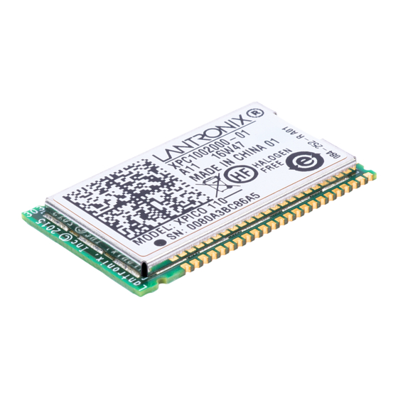
Page 27: Product Information Label
The product information label contains important information about your specific unit, such as its part number, revision, manufacturing date code, product model, country of origin, datamatrix barcode and MAC address. Figure 3-2 xPico Product Label Lantronix Datamatrix Part Number Barcode... -
Page 28: Specifications Electrical Specifications
Table 4-1 Absolute Maximum Ratings Parameter Symbol Units Supply Voltage Operating Temperature °C Storage Temperature °C Table 4-2 xPico 110 Recommended Operating Conditions Parameter Symbol Typical Units Supply Voltage 3.15 3.46 Supply Voltage Ripples CC_PP... -
Page 29: Technical Specifications
Storage capacity: 384 Kbytes Temperature Operating range: -40°C to +85°C (-40°F to 185°F) Warranty For details on the Lantronix warranty policy, go to our web site at www.lantronix.com/support/warranty. Included Software Windows 98/NT/2000/XP-based Lantronix® DeviceInstaller™ configuration software and Windows based Com Port Redirector EMI Compliance See A:Compliance. -
Page 30: Xpico 110 Mechanical Dimensions
4: Specifications xPico 110 Mechanical Dimensions Figure 4-4 Device Dimensions (in mm), Part 1 of 2 xPico® 110 Embedded Device Server Integration Guide... -
Page 31: Figure 4-5 Device Dimensions (In Mm), Part 2 Of 2
4: Specifications Figure 4-5 Device Dimensions (in mm), Part 2 of 2 Figure 4-6 Recommended Footprint (in mm) xPico® 110 Embedded Device Server Integration Guide... -
Page 32: A: Compliance
Compliance (According to ISO/IEC Guide 22 and EN 45014) Manufacturer’s Name & Address: Lantronix, Inc. 7535 Irvine Center Drive, Suite 100, Irvine, CA 92618 USA Declares that the following product: Product Name Model: xPico® 110 Wired Device Server Module Conforms to the following standards or other normative documents: Note: Tested when installed on the evaluation board. -
Page 33: Figure A-3 Certificate Of Compliance For Halogen Free
Figure A-3 Certificate of Compliance for Halogen Free xPico® 110 Embedded Device Server Integration Guide... -
Page 34: Federal Communication Commission Interference Statement
Lantronix, Inc. 7535 Irvine Center Drive Suite 100 Irvine, CA 92618 USA Tel: 949-453-3990 Fax: 949-453-3995 RoHS, REACH and WEEE Compliance Statement Please visit http://www.lantronix.com/legal/rohs/ for Lantronix's statement about RoHS, REACH and WEEE compliance. xPico® 110 Embedded Device Server Integration Guide...
Need help?
Do you have a question about the xPico 110 and is the answer not in the manual?
Questions and answers