Table of Contents
Advertisement
Quick Links
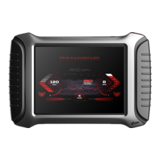
A80 BT Intelligent Diagnosis System
A80 user manual
1. This manual is designed for the usage of A80, applying to A80 automotive
diagnosis platform.
No part of this manual can be reproduced, stored in a retrieval system or transmitted, in any
form or by any means (electronic, mechanical, photocopying, recording, or otherwise),
without the prior written permission of Xtool.
2. This electronic control system diagnostic unit is designed for professional vehicle
maintenance technicians. It has a certain reliability, however, it can not exclude vehicle
damage and loss caused by customer technical problems, vehicle problems or other factors, so
users need to take risks.
3. Use the device only as described in this manual. The user will be responsible solely for the
after-effects of violating the laws and regulations caused by using the product or its data
information, Xtool will not bear any legal responsibility for that.
4. Xtool shall not be liable for any incidental or consequential damages or for any economic
consequential damages arising from the accidents of individual users and the third parties,
misuse or abuse of the device, unauthorized change or repair of the device, or the failure
made by the user not to use the product according to the manual.
5. All information, specifications and illustrations in this manual are based on the latest
configurations and functions available at the time of printing. Xtool reserves the right to make
changes at any time without notice.
6.
is the registered trademark of Shenzhen Xtooltech Co., Ltd.
7.In countries that the trademarks, service marks, domain names, logos and the name of the
company are not registered, Xtool claims that it still reserves the ownership of the
unregistered trademarks, service marks, domain names, logos and the company name. All
1
Advertisement
Table of Contents

Subscribe to Our Youtube Channel
Related Manuals for Xtool A80


Summary of Contents for Xtool A80
- Page 1 Xtool will not bear any legal responsibility for that. 4. Xtool shall not be liable for any incidental or consequential damages or for any economic consequential damages arising from the accidents of individual users and the third parties, misuse or abuse of the device, unauthorized change or repair of the device, or the failure made by the user not to use the product according to the manual.
-
Page 2: Table Of Contents
You may not use the trademarks, service marks, domain names, logos and company name of Xtool or other companies mentioned without written permission from the trademark holder. -
Page 3: Chapteri About A80 Bt
A80 BT Intelligent Diagnosis System 4.2 Test function: ......................18 4.3 Read ECU: ......................21 4.4 Read DTCs: ......................22 4.5 Clear DTCs: ......................23 4.6 Read live Data: ......................24 4.7 Special function: ..................... 25 4.8 Actuating components test: ..................25 5. - Page 4 A80 BT Intelligent Diagnosis System 1.1 Front view 1.2 Back view...
-
Page 5: Layout Of A80 Bt Tablet
A80 BT Intelligent Diagnosis System 2. Layout of A80 BT Tablet 2.1 Top View of A80 BT Tablet ① ② ③ ④ ⑤ ①USB3.0 interface: Wired data transmission ②Mini HDMI interface: Transmission of audio and video ③DB15 interface: Subsequent extended reservation port ④DC charging port: Charge for equipment, use 12V power supply... -
Page 6: Outline Diagram Of Vci Diagnostic Kit
A80 BT Intelligent Diagnosis System ①Seat adapter: This is reserved for the socket, and can be charged with charging. 2.3 Outline diagram of VCI diagnostic kit ①Display: For voltage display ②OBD interface (head): Used to connect vehicles with international standard OBDII diagnostic seats. -
Page 7: A80 Bt Technical Parameters
A80 BT Intelligent Diagnosis System VCI diagnostic box function: After inserting the vehicle diagnostic seat, it connects with A80 BT host computer by Bluetooth to realize wireless data transmission. 2.4 A80 BT technical parameters Operating system: Android Processor: quad core processor 1.8GHz Memory: 2GRAM, 32GROM Display / touch screen: 1024·768 resolution, 8 inch LED... -
Page 8: Chapter Ii How To Use A80 Bt
A80 BT Intelligent Diagnosis System Appearance size: 275·183·33.9 (mm) Chapter II How to use A80 BT A80 BT activation 1.1 In order not to affect the using and upgrading of newly released software, please be sure to activate A80 BT. - Page 9 A80 BT Intelligent Diagnosis System 1.2 First turn on the A80 BT host, enter the tablet setting function to enable the WLAN function, and connect to the wireless network. Click the A80 BT Diagnostics icon to activate the page: 1. Enter the activation code on the certificate;...
-
Page 10: A80 Bt Main Interface And Function Buttons Description
A80 BT Intelligent Diagnosis System to install. 2. A80 BT main interface and function buttons description 2.1 Main interface After A80 BT boot, the main interface and sub menu are shown below.▼ 2.2 Sub-menu and function buttons... - Page 11 A80 BT Intelligent Diagnosis System Functional Buttons Functional descriptions Diagnostic functions and special functions enter the button, and then select the desired functions for operation, such as reading diagnostic information, viewing data flow parameters, performing motion tests, special functions, etc.
- Page 12 A80 BT Intelligent Diagnosis System corresponding date and model to view. By selecting “Setting”, users can access the language setting and other system related settings. Online communication cloud Platform. After the user activates, you can upgrade the newly developed diagnostic software by directly clicking the one-click upgrade.
-
Page 13: Toolbar Functional Buttons
A80 BT Intelligent Diagnosis System This feature can accept Remote Assistance from the Xtool company Technical Support Center. 2.3 Toolbar functional buttons Functional Descriptions Buttons Return to previous interface decrease volume increase volume Return to the main interface of Android system Display recent usage procedures Press this button for screen captures. -
Page 14: Connection Diagnosis
3.1 Vehicle Connection test (1)The A80 BT host is connected to the vehicle through the VCI diagnostic box with the main test line. (2)Turn on the car ignition switch and press the A80 BT key to diagnose the vehicle (see diagram below). -
Page 15: Precautions Before Use
A80 BT Intelligent Diagnosis System ① A80 BT Mainframe ② VCI box (can be directly connected to the vehicle diagnostic seat or select ③⑤ Accessory after connecting the vehicle diagnostic seat) ③ Adapter cable (optional for non-standard OBD II 16pin connectors) ④... -
Page 16: Diagnosis
You should cancel the task before returning to the main interface for shutdown. (8)The use of A80 BT should be lightly handled, as far as possible to avoid vibration or impact. To ensure the service life of the touchscreen, touch the screen gently. -
Page 17: Menu Selection
A80 BT Intelligent Diagnosis System 4.1 Menu selection: (1)After the VCI box is connected to the car and the A80 BT host is successfully paired with the wireless Bluetooth, the diagnostic interface can be performed as shown in the following figure (2)The menu can be selected according to your needs: Choose... -
Page 18: Test Function
A80 BT Intelligent Diagnosis System (3)In addition to common system troubleshooting, the development team also develops a range of special diagnostic functions for some vehicles, as follows. 4.2 Test function: (1)Using "BMW car" as an example, select "Royal Car V8.70", and then select the "GX9"... - Page 19 A80 BT Intelligent Diagnosis System The main function menu for different cars is slightly different, and the following options are included in the common main features menu: Read version information: This function reads the ECU version information and displays it as “system identification” or “system information”...
- Page 20 A80 BT Intelligent Diagnosis System Read ECU: read the current fault code in the ECU. Read DTCs: Read the fault codes of the history store in the ECU. Clear DTCs: Clear the current and historical fault code memory stored in the ECU. It can be cleared only after all faults have been eliminated.
-
Page 21: Read Ecu
A80 BT Intelligent Diagnosis System is 80-105 degrees Celsius, the operating voltage and time of each sensor and actuator should be. Actuation components test: The main purpose is to determine whether these actuator components are working properly. Special Features: Special models only. -
Page 22: Read Dtcs
A80 BT Intelligent Diagnosis System 4.4 Read DTCs: Select the "Read fault code" function to read the electronic control ECU stored in the fault code, read the fault code when the screen will display the read fault code and fault code definition, as shown in the... -
Page 23: Clear Dtcs
A80 BT Intelligent Diagnosis System Tip: When the fault vehicle is detected, if the "system normal" or "No Trouble code" is displayed, the ECU does not store the relevant fault code or some fault phenomenon is not in the ECU monitoring range,... -
Page 24: Read Live Data
A80 BT Intelligent Diagnosis System code and the history of the fault code to clear all, clear the fault code before you need to confirm the failure code to record. As shown in the following figure. (2)Click "Yes" confirmation after clearing the fault code, such as normal communication will show "failure code cleanup success"... -
Page 25: Special Function
A80 BT Intelligent Diagnosis System please go to the diagnostic report inside the data playback for review. 4.7 Special function: The special functions of different vehicle systems will also be different. 4.8 Actuating components test: Test conditions: Follow the instructions, for example: The engine is not running and the ignition switch is turned on. -
Page 26: Setting
A80 BT Intelligent Diagnosis System (1)Return the menu to "dynamic diagnostic data" to see the "Action test" function menu, choose to display the system can be used to perform action test of the Actuator component menu. Tip: The "Action test" function is a part of the system to perform... - Page 27 A80 BT Intelligent Diagnosis System following 6 options are set: Language: Select the language and select the desired language in the language options on the right. Units: Select units of measure, metric or imperial tick...
- Page 28 1.Host click on the gear icon to enter settings, tap Bluetooth, and then click Search Bluetooth, Bluetooth name for the corresponding serial number ordiagnostic. 2、Then go to A80 BT app click Settings, turn on Bluetooth, tick, as shown in the following image:...
- Page 29 A80 BT Intelligent Diagnosis System Self-test: Check the VCI box yourself to see if there is a malfunction...
-
Page 30: Diagnose Report
A80 BT Intelligent Diagnosis System 6. Diagnose report Diagnostic Report is used for viewing and printing the saved files, such as Live Data, Trouble Codes or pictures generated in the process of diagnosis, users also can view a record of which cars have been previously tested. -
Page 31: Data Playback
The Data playback feature lets you see which cars, which systems, and playback of recorded data streams freeze frames. One-click upgrade: The A80 BT device no longer requires a card to be upgraded, just open the app and click Upgrade, as shown in the following figure. -
Page 32: Xtool Cloud System
Xtool users, but also access to an online database that provides extensive repair and... -
Page 33: Remote Control
Remote Assistance. How to accept support from the Xtool Technology Center 9.1 Turn on A80 BT and go to the A80 BT App 9.2 Click the "remote Control" application to open the TeamViewer interface. - Page 34 A80 BT Intelligent Diagnosis System the staff to complete the operation.
-
Page 35: Chapter Iii Location Of Diagnostic Link Connectors On Different Vehicle Models
A80 BT Intelligent Diagnosis System Chapter III Location of Diagnostic link connectors on Different vehicle Models 1. Diagnostic link connectors locations of various vehicle models: *AUDI A6: the OBD plug is on the lower left side of the dashboard, use SMART OBDII-16 connector. - Page 36 A80 BT Intelligent Diagnosis System *Benz S320,220 Chassis: the OBD plug is below the dashboard, use SMART OBDII-16 connector. *Benz C180: the OBD plug is on the left hand side of the engine bay, use Benz-38 connector. *Benz 300SEL 140 chassis: the OBD plug is on the left hand side of the engine bay, use Benz-38...
- Page 37 A80 BT Intelligent Diagnosis System *GM Buick: the OBD plug is below the dashboard, use SMART OBDII-16 connector. *GM Buick GL8 : the OBD plug is below the dashboard, use SMART OBDII-16 connector. *VW POLO: the OBD plug is below the dashboard, use SMART OBDII-16 connector.
- Page 38 A80 BT Intelligent Diagnosis System *BMW 735I: the OBD plug is in the right hands side of the engine bay, use BMW-20 connector. *VW Passat B5: the OBD plug is behind the gearlever and beside the parking brake lever. Lift the cover...
-
Page 39: Location Diagram Of Vehicle Diagnostic Link Connectors
A80 BT Intelligent Diagnosis System 2. Location diagram of vehicle diagnostic link connectors: Location diagram of pick-up truck diagnostic link connectors: Location diagram of utility vehicles diagnostic link connectors: Link diagram of small car diagnostic link connectors:... -
Page 40: Diagnostic Link Connectors Terminal Definition And Communication Protocols
A80 BT Intelligent Diagnosis System NOTE: Each vehicle manufacturer may use additional pins to diagnose a variety of systems. Not every manufacturer uses the same standard. The function on a certain pin will vary from manufacturer to manufacturer. Verify with the manufacturer. - Page 41 A80 BT Intelligent Diagnosis System Pin definition (reference material) Various pin definitions as follows: 1, Manufacturer definition 2, SAE J1850 bus positive 3, Manufacturer definition 4, Bodywork site 5, Signal site 6, ISO 15765-4 defined CAN high 7, ISO9141 and ISO14230 defined K line...
- Page 42 A80 BT Intelligent Diagnosis System 11, Manufacturer definition 12, Manufacturer definition 13, Manufacturer definition 14, ISO 15765-4 defined CAN low 15, ISO9141 and ISO14230 defined L line 16, Permanent positive voltage [1]1, 3, 8, 9, 11, 12 and 13 are defined by manufacturer.
-
Page 43: Chapter Iv Additional Information
A80 BT Intelligent Diagnosis System Chapter IV Additional Information 1. Description of OBDII and the function of sensor components 1.1 OBDII function description In 1994, the American Society of Automotive Engineers proposed the second generation of self-diagnosis system for on-board faults, namely OBD-II. - Page 44 A80 BT Intelligent Diagnosis System and OBD-I has been completely abandoned, other vehicles are generally OBD-I and OBD-II coexist. Electronic technology is applied to the engine management system. In addition to basic functions such as fuel injection and ignition functions, as well as on-board (OBD) function.
-
Page 45: Sensor Element Function
A80 BT Intelligent Diagnosis System development, which is further than OBD II, is on the agenda. The OBD III system mainly uses a small car wireless transceiver system to automatically notify the management department of the VIN, fault code and location of the vehicle through wireless cellular communication, satellite communication or GPS system. - Page 46 A80 BT Intelligent Diagnosis System Sensor connection example diagram (as shown below)▼ (1)ECU (Electronic Control Unit) The ECU is the control center of the electronically controlled engine, which can control the action of each actuator by receiving the engine operation information transmitted by each sensor.
- Page 47 A80 BT Intelligent Diagnosis System engine's operation is highly variable, so the calculation efficiency should be high. The final stage is controlled by the output voltage, which provides sufficient power to regulate the common rail pressure operating units (Actuator) and shut off the plunger supply. In addition, the actuator controls engine functions (e.g.
- Page 48 A80 BT Intelligent Diagnosis System up the dead point is in the compression stroke and then in the firing or exhaust stroke. This information is not available from the crankshaft position during starting. In contrast, the information generated by the crankshaft sensor is sufficient to determine the engine state while the vehicle is running.
- Page 49 A80 BT Intelligent Diagnosis System (optional). The sensor has a temperature-dependent resistance, the temperature coefficient of the resistor is negative, and the high-sensitivity NTC (negative temperature coefficient thermistor) resistance increases with temperature. It is a part of voltage divider circuit powered by 5V support.
- Page 50 A80 BT Intelligent Diagnosis System path. The plug-in sensor can be mounted in the air filter or in the measuring tube of the air guiding section. The measuring tubes are available in a variety of sizes depending on the maximum air flow required by the engine.
-
Page 51: Common Faults And Elimination Of Electronic Control System
A80 BT Intelligent Diagnosis System installed after the air intake heating device (if equipped). It is forbidden to enter the sensor during painting or cleaning. (6)Accelerator pedal sensor Unlike ordinary distribution pumps or in-line pumps, in diesel electrical control devices, the driver's acceleration requirements are no... - Page 52 A80 BT Intelligent Diagnosis System the fault still does not occur again, the occasional fault will be automatically cleared. After turning off the ignition switch 150 minutes, the microcomputer enters the self-holding stage, if the fuel injection and ignition system is repaired during this period, then the fault code that has been stored should be recalled and removed.
- Page 53 A80 BT Intelligent Diagnosis System clear the fault code. If there is no DRBII, the ignition switch can be turned ON/OFF 50 times and the fault code is cleared. Volvo Car Fault Self-Diagnostic System The interface of the Volvo series of self-diagnostic system is in the right front corner of the car body, the engine cover is opened, and the front left headlights have two diagnostic seats A and B.
- Page 54 A80 BT Intelligent Diagnosis System Hole 3 → ABS System Hole 5 → Turbocharging System Hole 6 → Ignition System Hole 7 → Instrument Diagnostic System Block B: Hole 1 → Central Air Conditioning Hole 2 → Constant Speed Control System Hole 5 →...
- Page 55 A80 BT Intelligent Diagnosis System 2 control component action test; 3 Each control element operates simultaneously to control the test; 4 Develop component motion command control test; 5 numerical reading analysis instructions; 6 Reset the microcomputer memory command. When diagnosing the car, you can use the jumper on the diagnostic...
- Page 56 A80 BT Intelligent Diagnosis System (installed in the upper left corner of the instrument cluster). To clear the fault code, turn on the ignition switch and connect the Tc and El terminals of the diagnostic interface with a jumper. Keep the car still, and press the brake pedal continuously for more than 8 times in 3 seconds.
- Page 57 FCC Statement This device complies with part 15 of the FCC rules. Operation is subject to the following two conditions: (1) this device may not cause harmful interference, and (2) this device must accept any interference received, including interference that may cause undesired operation. Changes or modifications not expressly approved by the party responsible for compliance could void the user's authority to operate the equipment.
Need help?
Do you have a question about the A80 and is the answer not in the manual?
Questions and answers