Table of Contents
Advertisement
Quick Links
Advertisement
Table of Contents

Subscribe to Our Youtube Channel
Related Manuals for EXFO IQS-2150


Summary of Contents for EXFO IQS-2150
- Page 1 User Guide IQS-2150 Light Source for IQS Platforms...
- Page 2 EXFO Inc. (EXFO). Information provided by EXFO is believed to be accurate and reliable. However, no responsibility is assumed by EXFO for its use nor for any infringements of patents or other rights of third parties that may result from its use.
-
Page 3: Table Of Contents
Contents Contents Certification Information ......................v 1 Introducing the IQS-2150 Light Source ............1 Main Features .........................1 Available Models ........................2 Typical Applications ........................2 Conventions ..........................3 2 Safety Information ..................5 3 Getting Started with Your Light Source ............. 7 Inserting and Removing Test Modules ..................7 Starting the Light Source Application ...................12... - Page 4 9 Warranty ......................53 General Information ......................53 Liability ..........................53 Exclusions ..........................54 Certification ..........................54 Service and Repairs .......................55 EXFO Service Centers Worldwide ..................56 A Technical Specifications ................57 B SCPI Command Reference ................59 Quick Reference Command Tree ...................60 Product-Specific Commands—Description ................61 Index .........................77...
-
Page 5: Certification Information
Electronic test and measurement equipment is exempt from FCC part 15, subpart B compliance in the United States of America and from ICES-003 compliance in Canada. However, EXFO Inc. makes reasonable efforts to ensure compliance to the applicable standards. The limits set by these standards are designed to provide reasonable protection against harmful interference when the equipment is operated in a commercial environment. -
Page 7: Introducing The Iqs-2150 Light Source
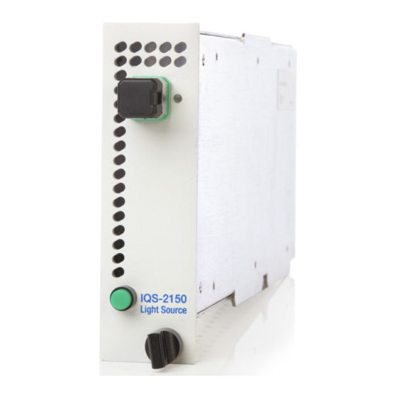
Main Features The IQS-2150 Light Source is designed for scientific and industrial applications using the IQS Platforms. The IQS-2150 Light Source includes a choice of multimode LEDs and single-mode DFB laser emitters, in single- and dual-wavelength configurations, for both singlemode and multimode test applications. -
Page 8: Available Models
For easy repeat access, the software stores multiple power level and modulation configurations. Its Windows-based software allows the IQS-2150 Light Source to integrate easily into any test system. The IQS-2150 Light Source supports local control (via the IQS Manager software) and remote control (through GPIB, RS-232, or Ethernet TCP/IP using SCPI commands or the provided LabVIEW drivers). -
Page 9: Conventions
Introducing the IQS-2150 Light Source Conventions Conventions Before using the product described in this guide, you should understand the following conventions: ARNING Indicates a potentially hazardous situation which, if not avoided, could result in death or serious injury. Do not proceed unless you understand and meet the required conditions. -
Page 11: Safety Information
Safety Information ARNING Do not install or terminate fibers while a light source is active. Never look directly into a live fiber and ensure that your eyes are protected at all times. ARNING The use of controls, adjustments and procedures, namely for operation and maintenance, other than those specified herein may result in hazardous radiation exposure or impair the protection provided by this unit. - Page 12 Safety Information Your IQS-2150 Light Source is a Class 1 laser or LED product in compliance with standards IEC 60825-1: 2007 and 21 CFR 1040.10, except for deviations pursuant to Laser Notice No. 50, dated June 24, 2007. Invisible laser radiation may be encountered at the output port.
-
Page 13: Getting Started With Your Light Source
Never insert or remove a module while the controller unit and its expansion units are turned on. This will result in immediate and irreparable damage to both the module and unit. AUTION To avoid damaging your unit, use it only with modules approved by EXFO. Light Source... - Page 14 2b. Gently pull the top of the protective cover downwards, to remove it from the unit grooves. Protective cover Retaining screw knob 3. Position the module so that its front panel is facing you and the top and bottom protruding edges are to your right. IQS-2150...
- Page 15 Getting Started with Your Light Source Inserting and Removing Test Modules 4. Insert the protruding edges of the module into the grooves of the unit’s module slot. Protruding edges (right side of module) Retaining screw knob Retaining screw 5. Push the module all the way to the back of the slot, until the retaining screw makes contact with the unit casing.
- Page 16 1. While pulling gently on the knob, turn it counterclockwise until it stops. The module will slowly be released from the slot. Retaining screw knob 2. Place your fingers underneath the module or hold it by the retaining screw knob (NOT by the connector) and pull it out. IQS-2150...
- Page 17 Getting Started with Your Light Source Inserting and Removing Test Modules Connector Retaining screw knob AUTION Pulling out a module by a connector could seriously damage both the module and connector. Always pull out a module by the retaining screw knob. 3.
-
Page 18: Starting The Light Source Application
Getting Started with Your Light Source Starting the Light Source Application Starting the Light Source Application Your IQS-2150 Light Source module can be configured and controlled from its dedicated IQS Manager application (available only in IQS Manager 4.0 or later). - Page 19 Getting Started with Your Light Source Starting the Light Source Application Note: Pressing the LED push button will only enable you to switch to the module application. The laser emission will not be activated. Note: To start the corresponding monitor window at the same time, click Start App.
- Page 20 Remote : Module controlled remotely, but local commands can also be used. Lockout : Module controlled remotely only. Module/unit status Current date and time For more information about automating or remotely controlling the IQS-2150 Light Source, refer to your platform user guide. IQS-2150...
-
Page 21: Exiting The Application
Getting Started with Your Light Source Exiting the Application Data Display In addition to the Control Center, the main window also contains the data display, where the source status indicator, as well as values for wavelength, modulation, and attenuation controls are shown (see figure below). Nominal wavelength Source status... -
Page 23: Setting Up Your Light Source
Note: You do not need to turn on the IQS-2150 Light Source or connect it to a DUT to set it up. To turn on the source, see Operating Your Light Source on page 27. -
Page 24: Selecting A Wavelength
Setting Up Your Light Source Selecting a Wavelength Selecting a Wavelength If you are using a dual-wavelength module, you can select a wavelength to perform your tests. When the source is activated, the wavelength appears in the top right corner. IQS-2150... - Page 25 Setting Up Your Light Source Selecting a Wavelength To select the desired wavelength: Click the appropriate button in the Wavelength panel. A green light identifies the selected wavelength. When you select a wavelength, you will see the message Stabilization in progress...
-
Page 26: Setting The Attenuation
Setting Up Your Light Source Setting the Attenuation Setting the Attenuation You can modify the power of the IQS-2150 Light Source output by attenuating the emitted signal. With some IQS-2150 Light Source models, the Attenuation control is grayed out during the stabilization period, which occurs after you have selected a wavelength if the source is activated. - Page 27 Setting Up Your Light Source Setting the Attenuation The attenuation value in the data display will then indicate the increased or decreased attenuation. As you change the attenuation value, you will notice that the numbers change from green to orange. After you release the attenuation controls, they revert to their original green color to indicate that the change has been applied to the source (when it is active).
-
Page 28: Selecting A Modulation Frequency
Selecting a Modulation Frequency Selecting a Modulation Frequency You can modulate the laser output of the IQS-2150 Light Source to simulate data transfer. A number of modulation frequencies are available. The modulation can be set to different values to better suit your testing needs. - Page 29 Setting Up Your Light Source Selecting a Modulation Frequency To select a modulation frequency: 1. Select a modulation frequency by choosing a value in the Modulation panel, as shown in the following figure. A green light identifies the selected modulation frequency. To indicate a successful selection, Stabilization in progress appears in the data display (only if the source is an active laser).
-
Page 30: Saving And Recalling Configurations
Setting Up Your Light Source Saving and Recalling Configurations Saving and Recalling Configurations Once you have set the IQS-2150 Light Source parameters, you can save your custom configuration and recall it at any time. You can also recall the factory-defined settings. - Page 31 Setting Up Your Light Source Saving and Recalling Configurations To recall a configuration: 1. Select the Configuration function tab. 2. Click Open. 3. Select the configuration file you wish to recall and confirm your action. You are returned to the application and the new parameters are set. To revert to factory settings: 1.
-
Page 33: Operating Your Light Source
To ensure maximum power and to avoid erroneous readings: Always inspect fiber ends and make sure that they are clean as explained below before inserting them into the port. EXFO is not responsible for damage or errors caused by bad fiber cleaning or handling. - Page 34 EXFO uses good quality connectors in compliance with EIA-455-21A standards. To keep connectors clean and in good condition, EXFO strongly recommends inspecting them with a fiber inspection probe before connecting them. Failure to do so will result in permanent damage to the connectors and degradation in measurements.
-
Page 35: Installing The Exfo Universal Interface (Eui)
Operating Your Light Source Installing the EXFO Universal Interface (EUI) Installing the EXFO Universal Interface (EUI) The EUI fixed baseplate is available for connectors with angled (APC) or non-angled (UPC) polishing. A green border around the baseplate indicates that it is for APC-type connectors. -
Page 36: Activating Or Deactivating Light Emission
Before activating the source, read carefully Safety Information on page 5. Upon source activation, the set parameter values are used. Therefore, make sure the source setup is correct before activation. Data display Red arrows Source status indicator Active LED Source On/Off button IQS-2150... -
Page 37: Viewing Results
33. Viewing Results You cannot view results directly using the IQS-2150 Light Source software. To view results, you must use modules and systems which perform tests. For more information, refer to test modules or system user guides, or call EXFO. -
Page 39: Monitoring Light Source Modules
Monitoring Light Source Modules When using your IQS-2150 Light Source module, either alone or with other modules in a test setup, you can view module data and status using its monitor window in IQS Manager. Using Monitor Windows Monitor windows display basic data about modules. A combination of resizable windows allows you to create an integrated data display (refer to the platform user guide). - Page 40 3. Click Start Monitor to apply your selection. IQS Manager will display the selected monitor windows on the Monitors function tab. Note: To start the highlighted module’s corresponding application at the same time, click Start App. & Monitor. The application will appear in a different window. IQS-2150...
- Page 41 Monitoring Light Source Modules Using Monitor Windows Remove Monitor button Rearrange Monitors button (1 or 2 columns) Close All Monitor window button arrow buttons Light Source...
-
Page 42: Using Quicktools
2. Using the arrow button in the upper left corner, select QuickTools. The corresponding monitor window flashes when QuickTools is activated. Note: If you want to open the actual application for your module rather than QuickTools, click Show Controller. IQS-2150... - Page 43 Monitoring Light Source Modules Using QuickTools For the IQS-2150 Light Source, one of the two QuickTools utility versions will be displayed, depending on the selected module, as shown in the following figure. Single- Dual- wavelength wavelength source source QuickTools QuickTools...
- Page 44 the selection arrows on both sides of the list (for details, see Selecting a Wavelength on page 18). Note: For single-source IQS-2150 modules, the Wavelength panel is not displayed. From the Modulation section, select a modulation frequency by ...
-
Page 45: Maintenance
Maintenance To help ensure long, trouble-free operation: Always inspect fiber-optic connectors before using them and clean them if necessary. Keep the unit free of dust. Clean the unit casing and front panel with a cloth slightly dampened with water. -
Page 46: Cleaning Fixed Connectors
Do not try to disassemble the unit. Doing so would break the connector. ARNING Looking into the optical connector while the light source is active WILL result in permanent eye damage. EXFO strongly recommends to TURN OFF the unit before proceeding with the cleaning procedure. - Page 47 9. Continue to turn as you withdraw the cleaning tip. 10. Repeat steps 7 to 9, but this time with a dry cleaning tip (2.5 mm tip provided by EXFO). Note: Make sure you don’t touch the soft end of the cleaning tip and verify the cleanliness of the cotton tip.
-
Page 48: Cleaning Eui Connectors
ARNING Looking into the optical connector while the light source is active WILL result in permanent eye damage. EXFO strongly recommends to TURN OFF the unit before proceeding with the cleaning procedure. - Page 49 6d. Verify connector surface with a portable fiber-optic microscope (for example, EXFO’s FOMS) or fiber inspection probe (for example, EXFO’s FIP). 7. Put the EUI back onto the instrument (push and turn clockwise).
-
Page 50: Recalibrating The Unit
Under normal use, the recommended interval for your IQS-2150 Light Source is: one year. For newly delivered units, EXFO has determined that the storage of this product for up to six months between calibration and shipment does not affect its performance (EXFO Policy PL-03). -
Page 51: Recycling And Disposal (Applies To European Union Only)
To ensure that your unit conforms to the published specifications, calibration may be carried out at an EXFO service center or, depending on the product, at one of EXFO’s certified service centers. Calibrations at EXFO are performed using standards traceable to national metrology institutes. -
Page 53: Troubleshooting
Solving Common Problems The following is a list of common problems along with their possible causes and some recommended actions to solve them. Note: In all cases, if problem persists after performing the recommended actions, contact EXFO. Problem Possible Cause Recommended Action LED push button does not Power not on. -
Page 54: Viewing Online Documentation
Troubleshooting Viewing Online Documentation Viewing Online Documentation An online version of the IQS-2150 Light Source user guide is available at all times from the application. To access the online user guide: Click Help in the function bar. IQS-2150... -
Page 55: Contacting The Technical Support Group
Contacting the Technical Support Group To obtain after-sales service or technical support for this product, contact EXFO at one of the following numbers. The Technical Support Group is available to take your calls from Monday to Friday, 8:00 a.m. to 7:00 p.m. - Page 56 Select the Technical Support tab to view phone numbers and active Internet links to EXFO’s Technical Support Group. Use these links to send an information request by e-mail or to access EXFO’s web site. Select the Module Information tab to view the module identification, ...
-
Page 57: Transportation
Troubleshooting Transportation Transportation Maintain a temperature range within specifications when transporting the unit. Transportation damage can occur from improper handling. The following steps are recommended to minimize the possibility of damage: Pack the unit in its original packing material when shipping. ... -
Page 59: Warranty
SPECIAL, INCIDENTAL, OR CONSEQUENTIAL DAMAGES. Liability EXFO shall not be liable for damages resulting from the use of the product, nor shall be responsible for any failure in the performance of other items to which the product is connected or the operation of any system of which the product may be a part. -
Page 60: Exclusions
Warranty Exclusions Exclusions EXFO reserves the right to make changes in the design or construction of any of its products at any time without incurring obligation to make any changes whatsoever on units purchased. Accessories, including but not limited to fuses, pilot lamps, batteries and universal interfaces (EUI) used with EXFO products are not covered by this warranty. -
Page 61: Service And Repairs
5. Return the equipment, prepaid, to the address given to you by support personnel. Be sure to write the RMA number on the shipping slip. EXFO will refuse and return any package that does not bear an RMA number. -
Page 62: Exfo Service Centers Worldwide
Crossing), No. 467, support.asia@exfo.com National Highway 107, Xixiang, Bao An District, Shenzhen, China, 518126 To view EXFO's network of partner-operated Certified Service Centers nearest you, please consult EXFO's corporate website for the complete list of service partners: http://www.exfo.com/support/services/instrument-services/ exfo-service-centers. IQS-2150... -
Page 63: A Technical Specifications
The following technical specifications can change without notice. The information presented in this section is provided as a reference only. To obtain this product’s most recent technical specifications, visit the EXFO Web site at www.exfo.com. a, b TECHNICAL SPECIFICATIONS DFB Laser Specifications... -
Page 65: Bscpi Command Reference
SCPI Command Reference This appendix presents detailed information on the commands and queries supplied with your IQS-2150 Light Source. MPORTANT Since the IQS controllers and expansion units can house many instruments, you must explicitly specify which instrument you want to remotely control. -
Page 66: Quick Reference Command Tree
SCPI Command Reference Quick Reference Command Tree Quick Reference Command Tree Command Parameter(s) SNUMber? SOURce[1..n] INTernal FREQuency <ModulationFreq[<wsp>HZ]> FREQuency? POWer ATTenuation <Attenuation[<wsp>DB]>|MAXim um|MINimum|DEFault ATTenuation? [MAXimum|MINimum|DEFault] STATe <PowerState> STATe? WAVelength UPPer|LOWer WAVelength? WAVelength COUNt? LOWer? UPPer? STATus? IQS-2150... -
Page 67: Product-Specific Commands-Description
SCPI Command Reference Product-Specific Commands—Description Product-Specific Commands—Description :SNUMber? Description This query returns a value indicating the serial number of the module. Syntax :SNUMber? Parameter(s) None Response Syntax <SerialNumber> Response(s) SerialNumber: The response data syntax for <SerialNumber> is defined as a <STRING RESPONSE DATA> element. - Page 68 DATA> element followed by an optional <SUFFIX PROGRAM DATA> element. The allowed <SUFFIX PROGRAM DATA> element is The <ModulationFreq> parameter is the new modulation frequency: 270, 1000, 2000, 100000 (Dither) or 0 (CW). Example(s) SOUR:POW:STAT ON SOUR:AM:INT:FREQ 2000Hz See Also SOURce[1..n]:AM:INTernal:FREQuency? IQS-2150...
- Page 69 SCPI Command Reference Product-Specific Commands—Description :SOURce[1..n]:AM:INTernal: FREQuency? Description This query returns a value indicating the current internal modulation frequency. If the source is in CW mode, the function will return 0. *RST sets the modulation frequency to 0 Hz (CW). Syntax :SOURce[1..n]:AM:INTernal:FREQuency? Parameter(s)
- Page 70 MAXimum allows to set the instrument to the greatest supported value. DEFault allows the instrument to select a value for the <Attenuation> parameter. The <Attenuation> parameter is the new power attenuation in dB. The power attenuation is always a positive value. IQS-2150...
- Page 71 SCPI Command Reference Product-Specific Commands—Description :SOURce[1..n]:POWer:ATTenuation Example(s) SOUR:POW:STAT ON SOUR:POW:ATT 2 Notes Instrument must be in the Ready state to execute this command. See Also SOURce[1..n]:POWer:ATTenuation? Light Source...
- Page 72 DATA> elements for this parameter are: MAXimum|MINimum|DEFault. MINimum is used to retrieve the instrument's smallest supported value. MAXimum is used to retrieve the instrument's greatest supported value. DEFault is used to retrieve the instrument's default value. Response Syntax <Attenuation> IQS-2150...
- Page 73 SCPI Command Reference Product-Specific Commands—Description :SOURce[1..n]:POWer:ATTenuation? Response(s) Attenuation: The response data syntax for <Attenuation> is defined as a <NR3 NUMERIC RESPONSE DATA> element. The <Attenuation> response is the power attenuation of the source, in dB. Example(s) SOUR:POW:STAT ON SOUR:POW:ATT 3 SOUR:POW:ATT? See Also SOURce[1..n]:POWer:ATTenuation...
- Page 74 ON corresponds to 1 and OFF corresponds to 0. The <PowerState> parameter is the new power state of the source. Example(s) SOUR:POW:STAT ON Notes Instrument must be in the Ready state to execute this command. See Also SOURce[1..n]:POWer:STATe? IQS-2150...
- Page 75 SCPI Command Reference Product-Specific Commands—Description :SOURce[1..n]:POWer:STATe? Description This query returns a value indicating the state of the optical source (on or off). *RST sets the optical source to OFF. Syntax :SOURce[1..n]:POWer:STATe? Parameter(s) None Response Syntax <PowerState> Response(s) PowerState: The response data syntax for <PowerState> is defined as a <NR1 NUMERIC RESPONSE DATA>...
- Page 76 LOWer, switches to the lowest wavelength. Example(s) SOUR:POW:WAV LOW Wait 3 seconds. SOUR:POW:STAT ON Notes Instrument must be in the Ready state to execute this command. This command can cause the instrument to enter the Stabilizing state. See Also SOURce[1..n]:POWer:WAVelength? SOURce[1..n]:POWer:WAVelength:LOWer? SOURce[1..n]:POWer:WAVelength:UPPer? IQS-2150...
- Page 77 SCPI Command Reference Product-Specific Commands—Description :SOURce[1..n]:POWer:WAVelength? Description This query returns a value indicating which wavelength is currently selected. *RST sets the selected wavelength to the LOW value. Syntax :SOURce[1..n]:POWer:WAVelength? Parameter(s) None Response Syntax <SelectedSources> Response(s) SelectedSources: The response data syntax for <SelectedSources>...
- Page 78 Response(s) NbWavelength: The response data syntax for <NbWavelength> is defined as a <NR1 NUMERIC RESPONSE DATA> element. The <NbWavelength> response is the number of wavelengths available on the instrument: 1, one wavelength available 2, two wavelengths available Example(s) SOUR:POW:WAV:COUN? IQS-2150...
- Page 79 SCPI Command Reference Product-Specific Commands—Description :SOURce[1..n]:POWer:WAVelength: LOWer? Description This query returns a value indicating the lower wavelength. *RST has no effect on this command. Syntax :SOURce[1..n]:POWer:WAVelength:LOWer? Parameter(s) None Response Syntax <LowerWavelength> Response(s) LowerWavelength: The response data syntax for <LowerWavelength> is defined as a <NR3 NUMERIC RESPONSE DATA>...
- Page 80 The response data syntax for <UpperWavelength> is defined as a <NR3 NUMERIC RESPONSE DATA> element. The <UpperWavelength> response is the highest source wavelength value in meters. Example(s) SOUR:POW:WAV:UPP? Notes Not available on single-source instruments. See Also SOURce[1..n]:POWer:WAVelength SOURce[1..n]:POWer:WAVelength? SOURce[1..n]:POWer:WAVelength:LOWer? IQS-2150...
- Page 81 SCPI Command Reference Product-Specific Commands—Description :STATus? Description This query returns a value indicating the status of the module (READY, BUSY, etc.). Syntax Parameter(s) None Response Syntax Response(s) Status: Example(s) STAT? Returns READY (Module is ready.) Light Source...
-
Page 83: Index
30 active LED............1 after-sales service ........49 equipment returns........55 application contacting EXFO support from ....50 baseplate ..........29 exiting ........... 15 main window description ...... 12 connector adapter ......... 29 EUI connectors, cleaning ......42 setting up .......... - Page 84 ..........56 mounting EUI connector adapter ....29 setting up attenuation, light source......20 light source ..........17 shipping to EXFO......... 55 online user guide ........48 slot number ..........14 opening monitor window ......34 software. see application operating the light source.....
- Page 85 Index source port............ 1 source. see light source specifications, product ........ 57 status bar ............ 14 storage requirements ........39 symbols, safety..........3 technical specifications........ 57 technical support ........49, 50 temperature for storage......39 title bar ............14 transportation requirements ....39, 51 user guide.
- Page 86 CHINESE REGULATION ON RESTRICTION OF HAZARDOUS SUBSTANCES NAMES AND CONTENTS OF THE TOXIC OR HAZARDOUS SUBSTANCES OR ELEMENTS CONTAINED IN THIS EXFO PRODUCT EXFO Indicates that this toxic or hazardous substance contained in all of the homogeneous materials for this part is below the limit requirement in SJ/T11363-2006...
- Page 87 MARKING REQUIREMENTS Product Environmental protection use period (years) Logo This E product EXFO Battery If applicable.
- Page 88 Tel.: 1 978 367-5600 · Fax: 1 978 367-5700 EXFO FINLAND Elektroniikkatie 2 FI-90590 Oulu, FINLAND Tel.: +358 (0) 403 010 300 · Fax: +358 (0) 8 564 5203 TOLL-FREE (USA and Canada) 1 800 663-3936 © 2015 EXFO Inc. All rights reserved. Printed in Canada (2015-07) ...
Need help?
Do you have a question about the IQS-2150 and is the answer not in the manual?
Questions and answers