
Related Manuals for EXFO IQS-8500 Series


Summary of Contents for EXFO IQS-8500 Series
- Page 1 User Guide Ethernet and Fibre Channel Application IQS-8500 Series and IQS-8120NGE/8130NGE for IQS-600...
- Page 2 EXFO Inc. (EXFO). Information provided by EXFO is believed to be accurate and reliable. However, no responsibility is assumed by EXFO for its use nor for any infringements of patents or other rights of third parties that may result from its use.
-
Page 3: Table Of Contents
Contents Certification Information ....................... ix 1 Introducing the Ethernet and Fibre Channel Application ......1 Conventions ..........................3 2 Safety Information ..................5 Laser Safety Warnings ......................5 Installation Instruction Warnings ....................6 3 Getting Started .................... 9 IQS Manager Installation ......................9 Inserting and Removing Test Modules ..................9 Turning the Unit On ........................9 4 Physical Interfaces and LEDs .............. - Page 4 Test Logger .........................131 8 Port Tabs ....................133 Electrical TX ........................134 Electrical RX ........................136 Optical TX ...........................138 Optical RX ...........................140 Interface Setup (Ethernet) ....................142 Interface Setup (Fibre Channel) ..................146 Network ..........................150 Advanced Auto-Neg. TX .....................154 Advanced Auto-Neg. RX .....................159 IQS-8500 Series and IQS-8120NGE/8130NGE...
- Page 5 9 Traffic Analyzer Tabs ................161 Ethernet TX .........................162 Ethernet RX ........................165 Ethernet Statistics .......................168 PBB-TE ..........................170 Higher Layers ........................172 Flow Control ........................174 Traffic Filters ........................177 Traffic Filter Configuration ....................182 Traffic Filter Stats ........................184 Capture ..........................186 Graph ..........................191 FC TX ..........................192 FC RX ..........................195 FC Latency ..........................197 FC Statistics ........................199...
- Page 6 19 Common Tab .....................363 Performance Monitoring (PM) ....................363 20 System Tabs ....................367 Preferences .........................368 Default/Ethernet Test Preferences ..................370 IPv6 Test Preferences ......................373 FC Test Preferences ......................376 Module Information ......................378 Software Options ........................380 Clock Synchronization ......................385 Remote Control ........................390 IQS-8500 Series and IQS-8120NGE/8130NGE...
- Page 7 24 Troubleshooting ..................447 Solving Common Problems ....................447 Contacting the Technical Support Group ................448 Transportation ........................448 25 Warranty ....................449 General Information ......................449 Liability ..........................450 Exclusions ...........................451 Certification ........................451 Service and Repairs ......................452 EXFO Service Centers Worldwide ..................453 Ethernet and Fibre Channel Application...
- Page 8 MAC Configuration ......................498 MPLS Configuration ......................499 UDP Configuration ......................501 TCP Configuration ......................501 Advanced TOS/DS .......................502 Ping ............................504 Filter Selection ........................506 Truncation Calculator ......................507 Field Match Configuration ....................508 Triggered Frame Details ......................510 Data Capture Export ......................511 Index .......................513 viii IQS-8500 Series and IQS-8120NGE/8130NGE...
-
Page 9: Certification Information
Electronic test and measurement equipment is exempt from FCC Part 15 compliance in the United States and from IC ICES 003 compliance in Canada. However, EXFO Inc. (EXFO) makes reasonable efforts to ensure compliance to the applicable standards. The limits set by these standards are designed to provide reasonable protection against harmful interference when the equipment is operated in a commercial environment. - Page 10 Laser This product complies with 21 CFR 1040.10 and with EN 60825-1. This product may employ a Class 1 or Class 1M laser SFP or XFP . The laser classification is reproduced on the SFP/XFP . IQS-8500 Series and IQS-8120NGE/8130NGE...
- Page 11 2006/95/EC - The Low Voltage Directive 2004/108/EC - The EMC Directive 2006/66/EC - The Battery Directive 93/68/EEC - CE Marking And their amendments Manufacturer’s Name: EXFO Inc. Manufacturer’s Address: 400 Godin Avenue Quebec, Quebec Canada, G1M 2K2 Equipment Type/Environment: Test & Measurement / Industrial Trade Name/Model No.:...
- Page 12 I, the undersigned, hereby declare that the equipment specified above conforms to the above Directives and Standards. Manufacturer Signature: Full Name: Stephen Bull, E. Eng Position: Vice-President Research and Development Address: 400 Godin Avenue, Quebec (Quebec), Canada, G1M 2K2 Date: February 1, 2009 IQS-8500 Series and IQS-8120NGE/8130NGE...
- Page 13 2006/95/EC - The Low Voltage Directive 2004/108/EC - The EMC Directive 2006/66/EC - The Battery Directive 93/68/EEC - CE Marking And their amendments Manufacturer’s Name: EXFO Inc. Manufacturer’s Address: 400 Godin Avenue Quebec, Quebec Canada, G1M 2K2 Equipment Type/Environment: Test & Measurement / Industrial Trade Name/Model No.:...
-
Page 15: Introducing The Ethernet And Fibre Channel Application
Introducing the Ethernet and Fibre Channel Application Fully integrated test solution for performance assessment of Fibre Channel and Ethernet transport networks. Complete EtherSAM™ (ITU-T Y.1564) test suite. EtherSAM is the new standard for testing Ethernet mobile backhaul and commercial services Throughput, back-to-back, latency and frame loss measurements as ... - Page 16 VLAN ID/Priority and MPLS ID/COS flows. This user guide covers the Ethernet and Fibre Channel testing of the following products: Ethernet (Electrical) Fibre Channel Model Electrical Optical 10/100/1000 Mbps 100/1000 Mbps 10 Gbps 1x/2x 4x/10x IQS-8510B IQS-8510G IQS-8525 IQS-8535 IQS-8120NGE IQS-8130NGE IQS-8500 Series and IQS-8120NGE/8130NGE...
-
Page 17: Conventions
Introducing the Ethernet and Fibre Channel Application Conventions Conventions Before using the product described in this guide, you should understand the following conventions: ARNING Indicates a potentially hazardous situation which, if not avoided, could result in death or serious injury. Do not proceed unless you understand and meet the required conditions. -
Page 19: Safety Information
Safety Information Laser Safety Warnings ARNING When the LASER LED is on, the IQS-8500 Series and IQS-8120NGE/8130NGE is receiving/emitting an optical signal. ARNING Do not install or terminate fibers while a laser source is active. Never look directly into a live fiber, and ensure that your eyes are protected at all times. -
Page 20: Installation Instruction Warnings
To reduce the risk of fire, use only No. 26 AWG or larger telecommunication line cord. AUTION No user serviceable parts are contained inside. Contact the manufacturer regarding service of this equipment. AUTION Keep all ventilation openings clear and unobstructed. IQS-8500 Series and IQS-8120NGE/8130NGE... - Page 21 Safety Information Installation Instruction Warnings MPORTANT All wiring and installation must be in accordance with local building and electrical codes acceptable to the authorities in the countries where the equipment is installed and used. AUTION Electrostatic Discharge (ESD) Sensitive Equipment: Plug-in modules can be damaged by static electrical discharge.
-
Page 23: Getting Started
Getting Started If the Ethernet and Fibre Channel Application has been purchased at the same time as the IQS-600, the Ethernet and Fibre Channel Application module is pre-installed with the appropriate IQS Manager software version. IQS Manager Installation The IQS Manager is the baseline software and thus needs to be installed on the IQS-600 before using the Ethernet and Fibre Channel Application module. -
Page 25: Physical Interfaces And Leds
Physical Interfaces and LEDs This section describes all IQS-8500 Series and IQS-8120NGE/8130NGE models, connectors (ports), and LEDs available on each module. IQS-8510B Model The IQS-8510B always comes with two electrical 10/1000/1000 Mbps Ethernet ports and two optical ports that can be used either for... - Page 26 Note: Port #1 is the port enabled with the IQS-8510B-1 module for 1000Base-T testing. LEDs Status Description LINK/ACT Ethernet link up. (Green) Ethernet link down. Flashing TX/RX activity. DUPLEX Full Duplex mode. (Yellow) Half Duplex mode. Flashing Collisions are detected. IQS-8500 Series and IQS-8120NGE/8130NGE...
- Page 27 Physical Interfaces and LEDs IQS-8510B Model Optical 100/1000 Mbps Ethernet or 1x/2x Fibre Channel The IQS-8510B-1 and IQS-8510B-2 modules provide respectively one or two optical ports for 1000Base-X Ethernet or Fibre Channel 1x/2x testing. The optical 100Base-FX Ethernet and Fibre Channel 1x/2x are available through software options.
- Page 28 Link up. (Green) Link down. Flashing TX/RX activity. DUPLEX Full Duplex mode. (Yellow) Half Duplex mode, or when using Available 100Base-X or Fibre Channel interface. with Ethernet Flashing Collisions are detected in half duplex mode. interface only IQS-8500 Series and IQS-8120NGE/8130NGE...
-
Page 29: Iqs-8510G Model
Physical Interfaces and LEDs IQS-8510G Model IQS-8510G Model IQS-8510G-LAN: One 10 Gigabit Ethernet LAN PHY (10.3125 Gbps) port (LC connector type). IQS-8510G-WAN: One 10 Gigabit Ethernet WAN PHY (9.953 Gbps) port (LC connector type). IQS-8510G-LAN/WAN: One 10 Gigabit Ethernet LAN/WAN PHY (10.3125 / 9.953 Gbps) port (LC connector type). - Page 30 Note: Do not replace an XFP while the test is running to avoid distorting results. First stop the test, replace the XFP, and then restart the test. Note: Only use EXFO supported XFPs. Using non-supported XFPs can affect the performance and accuracy of the optical port.
- Page 31 LEDs LASER LED: The red LASER LED is on when the IQS-8500 Series and IQS-8120NGE/8130NGE is emitting an optical laser signal. LINK/ACT LED: The LINK/ACT LED is on when the link is up, off when the link is down, and flashing when frames are transmitted and/or received.
- Page 32 IQS-8525 and IQS-8535 Models IQS-8525 Fibre Channel (1x/2x/4x) and Ethernet (10/100/1000M) analyzer. IQS-8535 Fibre Channel (1x/2x/4x/10x) and Ethernet (10/100/1000M / 10Gig) analyzer. Ethernet 10/100/1000M Clock (REF OUT) FC 1x/2x/4x Ethernet 100/1000M External Clock FC 10x Ethernet 10G IQS-8500 Series and IQS-8120NGE/8130NGE...
-
Page 33: Iqs-8525 And Iqs-8535 Models
Physical Interfaces and LEDs IQS-8525 and IQS-8535 Models The following table shows the list of available ports as well as a description and signals supported for each model. Port labelled Description Supported signal(s) Model FC 1x/2x/4x Optical IN/OUT port small Fibre Channel 1x, 2x, and 4x IQS-8525 ETHERNET... - Page 34 Physical Interfaces and LEDs IQS-8525 and IQS-8535 Models LEDs Status Description LINK/ACT Ethernet link up. (Green) Ethernet link down. Flashing TX/RX activity. DUPLEX Full Duplex mode. (Yellow) Half Duplex mode. Flashing Collisions are detected. IQS-8500 Series and IQS-8120NGE/8130NGE...
- Page 35 Physical Interfaces and LEDs IQS-8525 and IQS-8535 Models Optical Fibre Channel 1x/2x/4x or Ethernet 100/1000 Mbps The IQS-8525 module provides one optical port for Fibre Channel 1x/2x/4x testing. The optical Ethernet 100Base-FX and 1000Base-X are available through software options. Fibre Channel 1x/2x/4x and Ethernet testing are available through software options on the IQS-8535 model.
- Page 36 LEDs for Optical Ports Status Description LASER An optical signal is generated (Red) No optical signal is generated RX LED used Link up for Ethernet Link down and Fibre Channel Flashing TX/RX activity Link/Activity status IQS-8500 Series and IQS-8120NGE/8130NGE...
- Page 37 Physical Interfaces and LEDs IQS-8525 and IQS-8535 Models Fibre Channel 10x and 10G Ethernet The IQS-8525/IQS-8535 provides an optical port for Fibre Channel 10x or 10 Gigabit Ethernet LAN/WAN testing capability. Insert one of the following XFP optical transceiver into the ...
- Page 38 Note: Do not replace an XFP while the test is running to avoid distorting results. First stop the test, replace the XFP, and then restart the test. Note: Only use EXFO supported XFPs. Using non-supported XFPs can affect the performance and accuracy of the optical port.
- Page 39 IQS-8525 and IQS-8535 Models LEDs LASER LED: The red LASER LED is on when the IQS-8500 Series and IQS-8120NGE/8130NGE is emitting an optical laser signal. LINK/ACT LED: The LINK/ACT LED is on when the link is up, off when the link is down, and flashing when frames are transmitted and/or received.
-
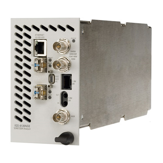
Page 40: Iqs-8120Nge And Iqs-8130Nge Models
External Clock FC 10x Ethernet 10G Note: Only the ports related to the Ethernet and Fibre Channel application are covered by this user guide; refer to the SONET/SDH user guide for more information on the other ports. IQS-8500 Series and IQS-8120NGE/8130NGE... - Page 41 Port connector type is RJ-45 for category 5 unshielded twisted pair (UTP) connection. Note: Refer to section A for cable specifications. Connect the 10/100/1000 electrical signal to be tested to the port ETHERNET 10/100/1000 of the IQS-8500 Series and IQS-8120NGE/8130NGE module. Ethernet and Fibre Channel Application...
- Page 42 Physical Interfaces and LEDs IQS-8120NGE and IQS-8130NGE Models LEDs Status Description LINK/ACT Ethernet link up. (Green) Ethernet link down. Flashing TX/RX activity. DUPLEX Full Duplex mode. (Yellow) Half Duplex mode. Flashing Collisions are detected. IQS-8500 Series and IQS-8120NGE/8130NGE...
- Page 43 IQS-8120NGE and IQS-8130NGE Models Optical 100/1000 Mbps Ethernet or 1x/2x/4x Fibre Channel The IQS-8500 Series and IQS-8120NGE/8130NGE module provides one optical port for 1000Base-X Ethernet testing or Fibre Channel 1x/2x/4x testing. The optical 100Base-FX Ethernet and Fibre Channel 1x/2x/4x are available through software options.
- Page 44 LEDs for Optical Ports Status Description LASER An optical signal is generated (Red) No optical signal is generated RX LED used Link up for Ethernet Link down and Fibre Channel Flashing TX/RX activity Link/Activity status IQS-8500 Series and IQS-8120NGE/8130NGE...
- Page 45 Physical Interfaces and LEDs IQS-8120NGE and IQS-8130NGE Models 10G Ethernet and Fibre Channel 10x The IQS-8525/IQS-8535 provides an optical port for 10 Gigabit Ethernet LAN/WAN or Fibre Channel 10x testing capability. Insert one of the following XFP optical transceiver into the 10-11.3G ...
- Page 46 Note: Do not replace an XFP while the test is running to avoid distorting results. First stop the test, replace the XFP, and then restart the test. Note: Only use EXFO supported XFPs. Using non-supported XFPs can affect the performance and accuracy of the optical port.
- Page 47 IQS-8120NGE and IQS-8130NGE Models LEDs LASER LED: The red LASER LED is on when the IQS-8500 Series and IQS-8120NGE/8130NGE is emitting an optical laser signal. LINK/ACT LED: The LINK/ACT LED is on when the link is up, off when the link is down, and flashing when frames are transmitted and/or received.
-
Page 49: Introducing The Smart User Interface
Starting the Module Application To Start the IQS-8500 Series and IQS-8120NGE/8130NGE Application: 1. Once your IQS-8500 Series and IQS-8120NGE/8130NGE module is installed, turn on the IQS-600. 2. In the IQS Manager main window, under Modules, press IQS-8500 Series and IQS-8120NGE/8130NGE once to select the module. - Page 50 Exiting the SUI while a test is created and standalone is enabled: Exiting the application will maintain the module alive as the Standalone mode is enabled. Are you sure you want to exit? IQS-8500 Series and IQS-8120NGE/8130NGE...
-
Page 51: Main Window
Introducing the Smart User Interface Main Window Main Window Minimize Tabs Help Application name Exit Tab(s) Tab’s Content Battery level / AC power Global test status Remote Test controls Date and time status Ethernet and Fibre Channel Application... - Page 52 Setup tab is part of the TEST tab and allows setting up the test. Refer to page 68 for more information. Once the test is created, other tabs containing one or two tabs are enabled allowing configuration of test parameters and viewing of the test status and results. IQS-8500 Series and IQS-8120NGE/8130NGE...
- Page 53 Introducing the Smart User Interface Main Window For Dual ports (IQS-8510B only), see the figure below for the localization of the port number on each tabs. Port 1 Port 2 Ethernet and Fibre Channel Application...
- Page 54 Expert Mode Tabs on page 425 System tab; refer to page 367 for more information. Tools tab; refer to page 391 for more information. About tab; gives information on EXFO company, contact, and product software release version. IQS-8500 Series and IQS-8120NGE/8130NGE...
- Page 55 Main Window Application Title Displays the software application title which is [x] - EXFO followed by the application name. Where x is the slot ID in which the module is inserted. A module description appears in front of the [x] slot ID when defined in IQS Manager.
- Page 56 Press OK and the help information is immediately displayed. It is also possible to navigate through the help information once the help window is open. IQS-8500 Series and IQS-8120NGE/8130NGE...
- Page 57 Introducing the Smart User Interface Main Window Exit For IQS-8510B, IQS-8510G, IQS-8525, and IQS-8535: The exit button ( X ) closes the current application. If a test is created, one of the following confirmation messages is displayed, based on the standalone feature status (enabled or not).
-
Page 58: Global Test Status And Controls
H (History): Indicates that alarms/errors occurred in the past. A grey background indicates that the test did not run yet, a green background indicates that no alarm/error has occurred, while a red background indicates that at least one alarm/error has occurred. IQS-8500 Series and IQS-8120NGE/8130NGE... - Page 59 Introducing the Smart User Interface Global Test Status and Controls Current status: Indicates the current alarm/error status of the test. A grey background indicates that the test is not running (--), a green background indicates that there is no alarm/error (NO ALARM), while a red background indicates that at least one alarm/error condition has occurred in the last second (ALARM).
- Page 60 : Provides access to 10 default or customer defined test case Favorites configurations. See Favorites on page 48 for more information. Only available when the test is running. Only available when the test is not running (Stop). IQS-8500 Series and IQS-8120NGE/8130NGE...
- Page 61 Global Test Status and Controls Remote Status Indicates whether the remote control feature is enabled/disabled and indicates the number of connections established with the IQS-8500 Series and IQS-8120NGE/8130NGE when enabled. Indicates that the remote control feature is disabled. Refer to the IQS-600 user guide for more information on how to enable it.
-
Page 62: Favorites
Allows to select a test case configuration. The test case configuration selected by default is the first one in the list. Note: Test cases not supported by the current IQS-8500 Series and IQS-8120NGE/8130NGE model and its options will not be created. - Page 63 Introducing the Smart User Interface Favorites Overwrite Selected Favorite Content The factory test case configurations can be modified as well as their default names. Favorite Name: Allows changing the name of the test case configuration file. A maximum of 32 characters are allowed in the name.
-
Page 64: Test Report Generation
Job Information: These parameters are used to identify the source of the report and are not mandatory. Enter the following job information if required: Job ID, Contractor, Customer, Operator Name, and Comment. Up to 256 characters are allowed for each parameter. IQS-8500 Series and IQS-8120NGE/8130NGE... - Page 65 Introducing the Smart User Interface Test Report Generation Report Settings: These parameters are used to identify the report and are not mandatory. Enter the following report information if needed: Report Title, Report Header, Selected Logo, and Report Format. Press Browse to select a different logo, then press Open. Report Format: Select the report file format.
- Page 66 Local memory (IQS-600): The file is saved locally on the IQS-600 memory. Network drive: The file is saved on a network drive. USB drive or Compact Flash: The file is saved on a removable drive. Close button: Closes the report generation settings window. IQS-8500 Series and IQS-8120NGE/8130NGE...
- Page 67 Introducing the Smart User Interface Test Report Generation Sections Tab Pre-defined selection: Allows selecting the type of report, and the window underneath allows selecting what will be part of the report. The default setting is Summary Report. Choices are: Summary Report selects the Summary report section only. Test Case Report selects all the report sections.
-
Page 68: Typical Tab Elements
LED indicates that there is no alarm/error, while a red LED indicates that at least one alarm/error condition has occurred in the last second. Note: The H and C LEDs are updated every second. IQS-8500 Series and IQS-8120NGE/8130NGE... - Page 69 Introducing the Smart User Interface Typical Tab Elements Alarm/Error Measurements Note: Alarms/Errors are only monitored once the test is started. Seconds: Gives the total number of the seconds in which one or more alarm/error occurred. Count: Gives the number of occurrences of a specific error. The count ...
- Page 70 Left and right scroll buttons are used to respectively move left and right allowing to see more tabs. The left and right scroll buttons are not always displayed; they are only displayed when required.1 Left and Right scroll buttons IQS-8500 Series and IQS-8120NGE/8130NGE...
-
Page 71: Tab Configuration
Introducing the Smart User Interface Tab Configuration Tab Configuration Once the test is created, other tabs next to the Test tabs are enabled allowing configuration of test parameters and viewing of the test status and results. A tab configuration button is available at the top-right part of each tab. Tab Configuration buttons Top tab Page/Tab... - Page 72 Tab name can be up to 35 characters long including the “/” and spaces. Top Page indicates the tab displayed at the top of the tab. Bottom Page indicates the tab displayed at the bottom of the tab. IQS-8500 Series and IQS-8120NGE/8130NGE...
- Page 73 Introducing the Smart User Interface Tab Configuration Defined Tabs Allows the selection of a tab. Up and down arrows are used to respectively move the selected page up or down in the list. Insert button allows the insertion of a new tab after the selected tab (the one highlighted) A maximum of 30 tabs can be displayed.
- Page 74 Return to the default page configuration layout. OK Button Accepts the page layout changes and jumps to the selected page (Defined tabs). Cancel Button Cancels the changes and returns to the page from where the tab configuration was launched. IQS-8500 Series and IQS-8120NGE/8130NGE...
-
Page 75: Keyboard Usage
Introducing the Smart User Interface Keyboard Usage Keyboard Usage The SUI pops up different keyboards to modify data. Following are the usual keyboard keys: Left arrow: Moves the cursor one position to the left. Right arrow: Moves the cursor one position to the right. ... - Page 76 Numerical keyboards: Allows entering integer/decimal values. For integer unsigned or signed values For rate values: Allows entering the rate values (0 through 9, and exponent) For IP address, Subnet Mask and Default Gateway values IQS-8500 Series and IQS-8120NGE/8130NGE...
- Page 77 Introducing the Smart User Interface Keyboard Usage Time Keyboard: Allows entering a time value. Date keyboard: Allows selecting a date by pressing the date on the calendar. Use the left and right arrow to switch from one month to another or press the month area for quick month selection.
- Page 78 Introducing the Smart User Interface Keyboard Usage Hexadecimal keyboards: Allows entering hexadecimal values (0 through 9 and A through F) For MAC address For IPv6 address IQS-8500 Series and IQS-8120NGE/8130NGE...
- Page 79 Introducing the Smart User Interface Keyboard Usage Full keyboard: Allows entering numbers, letters and some other characters. The Back, Del, Shift and space bar keys have the same functionality as a regular PC keyboard. Trace message keyboard (WAN): Allows entering alphanumerical ...
- Page 80 001 1100 IS4 Information Separator 4 000 1101 CR Carriage Return 001 1101 IS3 Information Separator 3 000 1110 SO Shift-Out 001 1110 IS2 Information Separator 2 000 1111 SI Shift-In 001 1111 IS1 Information Separator 1 IQS-8500 Series and IQS-8120NGE/8130NGE...
-
Page 81: Creating And Starting A Test Case
Creating and Starting a Test Case A test case can be created using one of the following methods: Test Setup allows the creation of the test case by travelling through the signal structure. See Introducing the Test Setup on page 68. See Test Case Availability to determine the test cases supported by the unit. -
Page 82: Introducing The Test Setup
Configuration section allows parameters configuration for each node of the test. Test Name represents the name of the test connection used to identify the test. The default setting is TEST. Note: The other configuration section parameters are described for each specific test. IQS-8500 Series and IQS-8120NGE/8130NGE... - Page 83 Creating and Starting a Test Case Introducing the Test Setup Test Setup Controls: Back returns to the previous configuration step allowing to see, change or delete what had been selected. Next switches to the next configuration step. The Next button is ...
- Page 84 The test path is created through the configuration of each layer that must be crossed by the signal under test. The test path can contain the following steps depending on the test application type: For IQS-8510B: For IQS-8510G: For IQS-8120NGE/IQS-8130NGE and IQS-8525/IQS-8535: IQS-8500 Series and IQS-8120NGE/8130NGE...
- Page 85 Creating and Starting a Test Case Introducing the Test Setup Steps Available with The Test step is the root of the test case. It allows the configuration All tests of the test name, test application type, Interface Type, topology, and Clock Mode.
-
Page 86: Test Case Availability
Ethernet BERT Test Case Ethernet Frame Analyzer Test Case including Multiple-Stream, Through Mode, MPLS, and PBB-TE testing. Ethernet Smart Loopback Test Case Ethernet TCP Throughput Test Case Fibre Channel BERT Test Case Through Mode only available on the IQS-8510B. IQS-8500 Series and IQS-8120NGE/8130NGE... -
Page 87: Ethersam (Y.1564) Test Case
Creating and Starting a Test Case EtherSAM (Y.1564) Test Case EtherSAM (Y.1564) Test Case ITU-T Y.1564 is the newly introduced standard for turning-up and troubleshooting carrier Ethernet services. This new methodology is completely adapted to today’s Ethernet services especially mobile backhaul and commercial services. - Page 88 1f. Leave the Dual Test Set check box cleared. For Dual Test Set test case, refer to Ethernet EtherSAM (Y.1564) and RFC 2544 Dual Test Set Test Cases on page 80. 1g. Press Next. IQS-8500 Series and IQS-8120NGE/8130NGE...
- Page 89 Creating and Starting a Test Case EtherSAM (Y.1564) Test Case 2. Port configuration: 2a. Select the port Connector Type (Optical or Electrical RJ-45). Optical is automatically selected for the Ethernet 10G interface. 2b. For IQS-8510B, select the port number by pressing on Port 1 or Port 2.
- Page 90 Speed, Duplex, and Flow Control parameters. Not available with Ethernet 10G. Refer to Interface Setup (Ethernet) on page 142 for more information. 4b. Set the VLAN parameters when required. Refer to Network on page 150 for more information. IQS-8500 Series and IQS-8120NGE/8130NGE...
- Page 91 Creating and Starting a Test Case EtherSAM (Y.1564) Test Case 4c. Select the Frame Format. Choices are Ethernet II and 802.3 SNAP . For 802.3 SNAP , select the Organizationally Unique Identifier (OUI). Refer to Network on page 150 for more information.
- Page 92 Ethernet II and 802.3 SNAP. Refer to Framing Configuration on page 494 for more information. 5e. Set the VLAN parameters when required. Refer to VLAN Configuration on page 482 for more information. 5f. Press Finish to complete the test setup. IQS-8500 Series and IQS-8120NGE/8130NGE...
- Page 93 Creating and Starting a Test Case EtherSAM (Y.1564) Test Case 6. Services must be enabled before starting the test. For enabling Services and for additional configuration parameters, refer to EtherSAM Tabs on page 325. 7. Press the Start button to start the test. At least one of the EtherSAM (Y.1564) sub tests (Service Configuration Test or Service Performance Test) has to be enabled to start the test.
-
Page 94: Ethernet Ethersam (Y.1564) And Rfc 2544 Dual Test Set Test Cases
IQS-8120NGE/IQS-8130NGE, or RTU-310/RTU-310G. A Dual Test Set test case must be first created on the remote module then on the local module as described in the following procedure. The results from local-to-remote and remote-to-local are available on the local testing unit. IQS-8500 Series and IQS-8120NGE/8130NGE... - Page 95 Creating and Starting a Test Case Ethernet EtherSAM (Y.1564) and RFC 2544 Dual Test Set Test Cases To create an EtherSAM (Y.1564) or RFC 2544 Dual Test Set test case, first create the test on the remote module as follow: 1.
- Page 96 Note: At this point you should have a link up indicated in the Tree view tab. A green LED indicates a link up while a red LED indicates a link down. For electrical port, if the link is down, make sure that the Ethernet port crossover setting is correct. 2c. Press Next. IQS-8500 Series and IQS-8120NGE/8130NGE...
- Page 97 Creating and Starting a Test Case Ethernet EtherSAM (Y.1564) and RFC 2544 Dual Test Set Test Cases 3. Optical configuration for Ethernet 10G interface only: 3a. Select the Transceiver Mode Choices are Local Area Network (LAN) for regular Ethernet interface (10.31250Gb/s) and Wide Area Network (WAN) for Ethernet stream encapsulated inside a SONET/SDH frame structure (9.95328Gb/s).
- Page 98 When the test is created as remote on a unit or on a compatible unit (IQS-8510B, IQS-8510G, IQS-8525/IQS-8535, IQS-8120NGE/IQS-8130NGE, or RTU-310/RTU-310G), the SUI is limited to the following: Test Setup, Tools, System, and About tabs; favorites, save, load, and report functionality. No test configuration and results are available. IQS-8500 Series and IQS-8120NGE/8130NGE...
- Page 99 Creating and Starting a Test Case Ethernet EtherSAM (Y.1564) and RFC 2544 Dual Test Set Test Cases Create the test on the local module as follow: 1. On the local module, proceed with the test creation as described above (starting with step 1 on page 81) at the exception of the following parameters: 1a.
- Page 100 Connection section. For IPv6, entering a Global IPv6 destination address requires that the interface Global IPv6 Address is defined. The Remote ID and its Status are displayed if the module is detected. Skip to step 1g. IQS-8500 Series and IQS-8120NGE/8130NGE...
- Page 101 Creating and Starting a Test Case Ethernet EtherSAM (Y.1564) and RFC 2544 Dual Test Set Test Cases 1e. Press Scan Subnet to scan the subnet to find remote compatible modules (IQS-8510B, IQS-8510G, IQS-8525/IQS-8535, IQS-8120NGE/IQS-8130NGE, AXS-850 Series (RFC 2544 only), FTB-860 Series, FTB-810/880 Series, or RTU-310/RTU-310G). The subnet scan will work only when both remote and local modules are on the same subnet.
- Page 102 3. On the local module, press the Start button to start the test. The Start button will be available only when the connection between the two IQS-8500 Series and IQS-8120NGE/8130NGE units is established. At least one of the test procedures (For EtherSAM (Y.1564): Service Configuration Test or Service Performance Test;...
-
Page 103: Ethernet Rfc 2544 Test Case
Creating and Starting a Test Case Ethernet RFC 2544 Test Case Ethernet RFC 2544 Test Case RFC 2544: Allows Ethernet Throughput, Back-to-Back, Frame Loss, and Latency performance tests in accordance with RFC 2544 specifications. Note: For bi-directional (Dual Test Set) test, see Ethernet EtherSAM (Y.1564) and RFC 2544 Dual Test Set Test Cases on page 80. - Page 104 Refer to Latency on page 317 for more information. 1e. Leave the Dual Test Set check box cleared. For Dual Test Set test case, refer to Ethernet EtherSAM (Y.1564) and RFC 2544 Dual Test Set Test Cases on page 80. 1f. Press Next. IQS-8500 Series and IQS-8120NGE/8130NGE...
- Page 105 Creating and Starting a Test Case Ethernet RFC 2544 Test Case 2. Port configuration: 2a. Select the port Connector Type (Optical or Electrical RJ-45). Optical is automatically selected for the Ethernet 10G interface. 2b. For IQS-8510B, select the port number by pressing on Port 1 or Port 2.
- Page 106 Not available with Ethernet 10G. Refer to Interface Setup (Ethernet) on page 142 for more information. 4b. Set the IP Version (IPv4 or IPv6). IP Version is only available when the IPv6 software option (SK-IPV6) is enabled. 4c. Press Next. IQS-8500 Series and IQS-8120NGE/8130NGE...
- Page 107 Creating and Starting a Test Case Ethernet RFC 2544 Test Case 5. Traffic stream configuration 5a. For IPv4, select the Automatic IP Address check box to dynamically obtain an IP address from a DHCP (Dynamic Host Configuration Protocol) server or set the source and destination IP addresses, Subnet Mask, and the Default Gateway.
- Page 108 Back-to-Back, Frame Loss or Latency) has to be enabled to start the test. Test procedures that are enabled will be performed following this order: Throughput, Back-to-Back, Frame Loss, and Latency. 8. For additional results, refer to RFC 2544 Tabs on page 299. IQS-8500 Series and IQS-8120NGE/8130NGE...
-
Page 109: Ethernet Bert Test Case
Creating and Starting a Test Case Ethernet BERT Test Case Ethernet BERT Test Case Allows Ethernet unframed and Layer 1 up to Layer 4 traffic generation with specific test pattern for Bit Error Rate analysis. Typical BERT applications in Single Port: Typical BERT application in Dual Ports (IQS-8510B only): Ethernet and Fibre Channel Application... - Page 110 However, before pressing Finish, press Back several times to return to the port setup window, select the second port and proceed with the rest of the configuration for the second port. IQS-8500 Series and IQS-8120NGE/8130NGE...
- Page 111 Creating and Starting a Test Case Ethernet BERT Test Case 2c. For Electrical RJ-45, if required, select the Ethernet port crossover check box to inverse the pin-to-pair assignment of the UTP cable used. Note: At this point you should have a link up indicated in the Tree view tab. A green LED indicates a link up while a red LED indicates a link down.
- Page 112 MAC address, type/length, and FCS bytes). Ethernet II 802.3 SNAP Note: For Layer 3 and Layer 4, choose Ethernet Framed Layer 2 and refer to Stream Generation Tabs - Overview on page 202 once the test is created. IQS-8500 Series and IQS-8120NGE/8130NGE...
- Page 113 Creating and Starting a Test Case Ethernet BERT Test Case 4b. For Ethernet Unframed, select the Enable Sync check box to allow any receiver to bit-sync every second by inserting an IFG of 12 bytes with SOF. The Enable Sync check box is not selected by default.
- Page 114 VLAN and its parameters (VLAN Config button). For more information on VLAN refer to MAC on page 220. 5f. Enter the Frame Size. For more information on Frame Size refer to Size on page 211. IQS-8500 Series and IQS-8120NGE/8130NGE...
- Page 115 Creating and Starting a Test Case Ethernet BERT Test Case 5g. Enter the Maximum Rate (%), the default setting is 100% for all speeds except for 10Gbps WAN which is 92.3076923076923%. Refer to Traffic Shaping on page 215 for more information. 5h.
-
Page 116: Ethernet Frame Analyzer Test Case
Frame Analyzer test allows also to perform IPTV, Through Mode, MPLS, and PBB-TE testing. IPTV and Through Mode are only available with IQS-8510B. Typical Frame Analyzer application in Single Port: Typical Frame Analyzer application in Dual Ports (IQS-8510B only): Typical Frame Analyzer application in Through Mode: IQS-8500 Series and IQS-8120NGE/8130NGE... - Page 117 Creating and Starting a Test Case Ethernet Frame Analyzer Test Case To create a Frame Analyzer test case: 1. Test configuration: 1a. Select Ethernet 10/100/1000 or Ethernet 10G as the Interface Type. Interface Type is not available with IQS-8510G. 1b. For IQS-8510B: Select the Topology test type: Single Port or Dual Ports.
- Page 118 Note: At this point you should have a link up indicated in the Tree view tab. A green LED indicates a link up while a red LED indicates a link down. For electrical port, if the link is down, make sure that the Ethernet port crossover setting is correct. 2d. Press Next. IQS-8500 Series and IQS-8120NGE/8130NGE...
- Page 119 Creating and Starting a Test Case Ethernet Frame Analyzer Test Case 3. Optical configuration for Ethernet 10G interface only: 3a. Select the Transceiver Mode Choices are Local Area Network (LAN) for regular Ethernet interface (10.31250Gb/s) and Wide Area Network (WAN) for Ethernet stream encapsulated inside a SONET/SDH frame structure (9.95328Gb/s).
- Page 120 Note: For dual ports, if PBB-TE or MPLS feature has been enabled on the first port, only the same feature may be enabled on the second port. Note: For IPTV and Through Mode tests press Finish, otherwise press Next. IQS-8500 Series and IQS-8120NGE/8130NGE...
- Page 121 Creating and Starting a Test Case Ethernet Frame Analyzer Test Case 5. Traffic stream configuration: 5a. Select the traffic stream to be configured, then set its parameters. Up to 10 streams can be configured with Frame Analyzer test. IPv4 IPv6 5b.
- Page 122 Layer 4, refer to Stream Generation Tabs on page 201. 7. Press the Start button to start the test. 8. For additional results, refer to Traffic Analyzer Tabs on page 161 and Stream Analyzer Tabs on page 239. IQS-8500 Series and IQS-8120NGE/8130NGE...
-
Page 123: Ethernet Smart Loopback Test Case
Creating and Starting a Test Case Ethernet Smart Loopback Test Case Ethernet Smart Loopback Test Case Allows transmitting back the received Ethernet stream of data while interchanging the source and destination addresses of the MAC and IP , in addition to the source and destination ports for UDP and TCP layers. To create a Smart Loopback test case: 1. - Page 124 Note: At this point you should have a link up indicated in the Tree view tab. A green LED indicates a link up while a red LED indicates a link down. For electrical port, if the link is down, make sure that the Ethernet port crossover setting is correct. 1h. Press Next. IQS-8500 Series and IQS-8120NGE/8130NGE...
- Page 125 Creating and Starting a Test Case Ethernet Smart Loopback Test Case 2. Optical configuration for Ethernet 10G interface only: 2a. Select the Transceiver Mode Choices are Local Area Network (LAN) for regular Ethernet interface (10.31250Gb/s) and Wide Area Network (WAN) for Ethernet stream encapsulated inside a SONET/SDH frame structure (9.95328Gb/s).
- Page 126 3e. Press Finish to complete the test setup. The Alarm summary tab is automatically displayed. 4. Press the Start button to start the test. 5. For additional results, refer to Traffic Analyzer Tabs on page 161. IQS-8500 Series and IQS-8120NGE/8130NGE...
-
Page 127: Ethernet Tcp Throughput Test Case
Creating and Starting a Test Case Ethernet TCP Throughput Test Case Ethernet TCP Throughput Test Case TCP Throughput (not available with Ethernet 10G interface): Allows sending TCP/IP traffic to the network and provides an average of the TCP Throughput based on the successfully transported bytes over the test time. Two units running a TCP Throughput test are required. - Page 128 3c. Set the IP Address (IPv4), Automatic IP address, Subnet Mask, and Default Gateway parameters. Refer to Source IP Configuration on page 152 for more information. 3d. Press Finish to complete the test setup. The Alarm summary tab is automatically displayed. IQS-8500 Series and IQS-8120NGE/8130NGE...
- Page 129 Creating and Starting a Test Case Ethernet TCP Throughput Test Case 4. Press the TCP Throughput tab and TCP Throughput Configuration tab. 4a. Select Remote as the TCP Mode. 4b. Enter the IP address of the local module in the Listening IP Address field.
-
Page 130: Fibre Channel Bert Test Case
1a. Select Fibre Channel as the Interface Type. Fibre Channel is only available with BERT test. 1b. For IQS-8510B: Select the Topology test type: Single Port or Dual Ports. 1c. Select BERT as the Application Type. 1d. Press Next. IQS-8500 Series and IQS-8120NGE/8130NGE... - Page 131 Creating and Starting a Test Case Fibre Channel BERT Test Case 2. Port configuration: 2a. For IQS-8510B, select the port number by pressing on Port 1 or Port 2. For IQS-8510B in Dual Ports, select the first port and proceed with the rest of the configuration for the first port.
- Page 132 Header and CRC. Refer to Size on page 231 for more information on the frame size. Note: There is nothing to configure for FC Framed Layer 1 and FC Framed Layer 2. 3b. Press Next. IQS-8500 Series and IQS-8120NGE/8130NGE...
- Page 133 Creating and Starting a Test Case Fibre Channel BERT Test Case 4. Framing configuration (available with FC Framed Layer 2 only): 4a. Set the network parameters. Refer to Interface Setup (Fibre Channel) on page 146 for more information. 4b. Select the Login check box to generate a login process when pressing on the Login button.
-
Page 135: Summary Tabs
Summary Tabs The summary tabs allow to configure the test parameters and to view the test status and results. Available with Page Ethernet Fibre Channel Test Summary Alarm Summary Not supported on IQS-8510G. Test Summary Gives the test configuration, status, and timer configuration. Press TEST, Summary, and Test. - Page 136 Enable Criteria check box cleared. Global Verdict for EtherSAM test: Indicates the actual test PASS or FAIL verdict. A FAIL verdict is declared when a Link Down, LOS, or any SLA parameter fails during the test. IQS-8500 Series and IQS-8120NGE/8130NGE...
- Page 137 Summary Tabs Test Summary SAM Test Status: Indicates the EtherSAM test status message. Test Status Desciption Pending (--) No sub test is started. A sub test is currently running. Running... Data Transfer... A sub test is running but no test traffic is being transmitted.
- Page 138 Throughput (Not available on IQS-8510G). Only BERT is available with Fibre Channel. Test Name: The name of the test connection is used to identify the test. A maximum of 8 characters are allowed. The default setting is TEST. IQS-8500 Series and IQS-8120NGE/8130NGE...
- Page 139 Summary Tabs Test Summary Clock Configuration Clock Mode indicates the clock mode selected during the test setup. Available with 10Gig-E WAN interface only. Possible choices are: Clock Mode LAN WAN Internal: Internal clock of the unit (STRATUM 3). Internal is the only available clock when 10GigE LAN transceiver mode is selected with Frame Analyzer, BERT, or RFC 2544 test.
- Page 140 Time field is updated to indicate the time the test will stop. User Duration: Allows the selection of the test duration when User Defined has been selected for duration. Choices are from 1 second to 30 days. The default setting is 15 minutes. IQS-8500 Series and IQS-8120NGE/8130NGE...
- Page 141 Note: When using Visual Guardian Lite for remote control, the timer configuration values will be based on the PC clock and not on the IQS-8500 Series and IQS-8120NGE/8130NGE. Make sure to consider the time zone differential if it exists between the PC and the IQS-8500 Series and IQS-8120NGE/8130NGE. Alarm Analysis LOC indicates that the IQS-8510G is unable to synchronize with the selected test clock.
-
Page 142: Alarm Summary
Dual ports test (IQS-8510B) Note: The list of available alarms and errors depends on the test case. For Dual Ports test, available with IQS-8510B, the alarms and errors are independently displayed for Port 1 and Port 2 when applicable. IQS-8500 Series and IQS-8120NGE/8130NGE... - Page 143 Summary Tabs Alarm Summary Test Global: Indicates the presence of any alarms/errors related to the test such as Port, WIS, Ethernet, Pattern, High Layer Protocol, Fibre Channel, and Other. Fibre Channel is not available with IQS-8510G. Log Full: Indicates that the logger exceeds it maximum capacity of 5000 events.
- Page 144 Pattern (BERT): Indicates the presence of any alarms/errors related to pattern testing such as No Traffic, Pattern Loss, and Bit Error. Indicates also the Bit Error rate and count. Other: Indicates all other alarms/errors such as SDT (Available with Ethernet BERT test only). IQS-8500 Series and IQS-8120NGE/8130NGE...
-
Page 145: Test Logger
Summary Tabs Test Logger Test Logger Press TEST, Summary, and Alarm. The Test Logger lists the test status/events. Total Events Indicates the total number of recorded events. Note: The Logger lists a maximum of 5000 events, over that amount the logger stops recording and the log full alarm is activated. - Page 146 Count: Indicates the number of occurrences of the error. Rate: Indicates the error rate. Note: In the Duration, Count and Rate columns, Pending indicates that the alarm/error condition persists or was persisting when the test was stopped. IQS-8500 Series and IQS-8120NGE/8130NGE...
-
Page 147: Port Tabs
Port Tabs The port tabs allow to configure different port parameters and to view the port analysis. Note: The available tabs listed depend on the activated test path. Available with Page Ethernet Fibre Channel Electrical TX Electrical RX Optical TX Optical RX Interface Setup (Ethernet) Interface Setup (Fibre Channel) -
Page 148: Electrical Tx
Press TEST, Port, and Electrical TX. Configuration Ethernet port crossover: Allows selecting the type of cable used. When disabled, the cable used should be straight through. When enabled, the cable used should be crossover. IQS-8500 Series and IQS-8120NGE/8130NGE... - Page 149 Port Tabs Electrical TX Frequency Note: Frequency offset generation is only available on the IQS-8510B. However, it is not available for 10Base-T test and when Through Mode is selected. Frequency Offset (ppm): Allows entering a positive or a negative frequency offset in ppm.
-
Page 150: Electrical Rx
100Base-T For IQS-8510B: 125000000 bps ±12500 bps (±100 ppm) For IQS-8120NGE/IQS-8130NGE and IQS-8525/IQS-8535: 125000000 bps ±15000 bps (±120 ppm) 1000Base-T For IQS-8510B: 1250000000 bps ±125000 bps (±100 ppm) For IQS-8120NGE/IQS-8130NGE and IQS-8525/IQS-8535: 1250000000 bps ±150000 bps (±120 ppm) IQS-8500 Series and IQS-8120NGE/8130NGE... - Page 151 Port Tabs Electrical RX Frequency Analysis Note: Frequency Analysis is not available for 10Base-T test. Frequency (bps): Indicates the frequency of the input signal. Frequency Offset: Indicates the offset between the standard rate specification and the rate of the input signal. Max.
-
Page 152: Optical Tx
Note: Alarm generation is not available with RFC 2544 test. Type LOS (Loss Of Signal): Turns off the output port laser signal. On/Off button: Allows enabling the alarm generation. This setting is disabled (Off) by default. IQS-8500 Series and IQS-8120NGE/8130NGE... - Page 153 Port Tabs Optical TX Frequency Note: Frequency offset is not available when Through Mode (IQS-8510B only) is selected. Frequency Offset (ppm): Available with FC 1x/2x/4x/10x, and 10 Gig-E interfaces only. Allows entering a positive or a negative frequency offset in ppm. The default setting is 0. Actual Frequency (bps): Available with FC 1x/2x/4x/10x, and 10 Gig-E ...
-
Page 154: Optical Rx
1000 Mbps IQS-8510B: 1.25 Gbps ± 125 Kbps (±100 ppm) IQS-8120NGE/IQS-8130NGE/IQS-8525/IQS-8525: 1.25 Gbps ± 150 Kbps (±120 ppm) 10 Gig-E LAN IQS-8510G: 10.3125 Gbps ± 1031.25 Kbps (±100 ppm) IQS-8120NGE/IQS-8130NGE/IQS-8525/IQS-8525: 10.3125 Gbps ± 1392.1875 Kbps (±135 ppm) IQS-8500 Series and IQS-8120NGE/8130NGE... - Page 155 Port Tabs Optical RX Interface Standard Rate Specification 10 Gig-E WAN IQS-8510G: 9.95328 Gbps ± 995.33 Kbps (±100 ppm) IQS-8120NGE/IQS-8130NGE/IQS-8525/IQS-8525: 9.95328 Gbps ± 1343.6928 Kbps (±135 ppm) FC 1x 1.0625 Gbps ± 127.5 Kbps (±120 ppm) FC 2x 2.125 Gbps ± 255 Kbps (±120 ppm) FC 4x 4.25 Gbps ±...
-
Page 156: Interface Setup (Ethernet)
Press TEST, Port1/2, and Interface. Configuration Note: The port configuration parameters are disabled when Advanced Auto-Neg. TX on page 154 is enabled. For IQS-8510B, allAll port 1 and port 2 configuration parameters are coupled when Through Mode is selected. IQS-8500 Series and IQS-8120NGE/8130NGE... - Page 157 Port Tabs Interface Setup (Ethernet) Enable Auto-Negotiation (Not available on IQS-8510G) The Auto-Negotiation should be selected if the remote connected port is also set to Auto-Negotiation, otherwise it should be deactivated. When selected, the Ethernet and Fibre Channel Application will indicate to the remote port which parameters to use.
- Page 158 Note: Flow Control should be set to None with Half Duplex mode. Local Clock Only available for 1Gbps electrical when auto-negotiation is disabled. Choices are Local, Remote, and Automatic. The default setting is Automatic. IQS-8500 Series and IQS-8120NGE/8130NGE...
- Page 159 Port Tabs Interface Setup (Ethernet) Status Link: A green Link LED indicates that there is a link at the input port of the corresponding Ethernet interface. A grey LED indicates that there is no link at the input port of the corresponding Ethernet interface. Auto-Negotiation: Indicates the auto-negotiation status (Not available ...
-
Page 160: Interface Setup (Fibre Channel)
Active mode when the PSP (Link Protocol) check box is cleared. The PSP (Link Protocol) check box is selected by default. Speed Select the speed of the connected FC interface. Choices are 1X, 2X, 4X, and 10X. IQS-8500 Series and IQS-8120NGE/8130NGE... - Page 161 Port Tabs Interface Setup (Fibre Channel) Login The capability to log in is available only if a successful link has been established with Framed Layer 2. Enable: Allows, when the Enable check box is selected, to either generate a login process when clicking on the Login button, or to accept a remote Login command.
- Page 162 Advertised BB_Credit when the Enable Login check box is selected. Changing the Advertised BB_Credit requires to manually re-send a login using the Login button. The capability to log in is available only with Framed Layer 2 when a successful link has been established. IQS-8500 Series and IQS-8120NGE/8130NGE...
- Page 163 Buffer-to-Buffer Flow Control Enable: The Enable check box is forced selected when Login is selected. The IQS-8500 Series and IQS-8120NGE/8130NGE will send a Received Ready (R_RDY) automatically after receiving a frame when the Enable check box is selected. Note: Since R_RDY are inserted between frames and have higher priority, in certain condition they may affect the TX throughput.
-
Page 164: Network
Coupled to stream check box is selected. Thus only the source MAC Address, and MPLS parameters are configurable. The Coupled to stream check box is selected by default. The Coupled to stream check box is not available with RFC 2544, Smart Loopback, and TCP Throughput tests. IQS-8500 Series and IQS-8120NGE/8130NGE... - Page 165 Port Tabs Network Source MAC Configuration MAC Address: A default and unique Media Access Control (MAC) address is automatically given to the Ethernet port. Select the MAC Address field if the MAC address has to be changed for this port and enter the new MAC address.
- Page 166 This setting is disabled by default. Note: IP Address and Subnet Mask are not available when the Automatic IP Address check box is selected. However, the IP Address obtained from the DHCP server will be displayed in the IP Address field. IQS-8500 Series and IQS-8120NGE/8130NGE...
- Page 167 Port Tabs Network For IPv6: Displays the Link-Local IPv6 Address, Global IPv6 Address, and Default Gateway Address. IPv6 Config button allows to configure the IPv6 addresses. Refer to IPv6 Address Configuration on page 487 for more information. Frame Format Frame Format allows to select Ethernet II or 802.3 SNAP frame ...
-
Page 168: Advanced Auto-Neg. Tx
The Auto-Negotiation will use either the Configuration (Speed, Duplex and Flow Control) settings, or the Local Capabilities when enabled. The port configuration settings from the Interface Setup (Ethernet) on page 142 are disabled when Advanced Auto-Neg. Mode is enabled. IQS-8500 Series and IQS-8120NGE/8130NGE... - Page 169 Port Tabs Advanced Auto-Neg. TX Configuration The Speed, Duplex, and Flow Control can be modified only when the Enable Local Capabilities is disabled. Speed: Select the speed of the connected interface. Choices are: For electrical port: 10Mbps, 100Mbps, 1Gbps, and Auto. For optical port: 1Gbps.
- Page 170 Asym. & Sym. Asym. & Sym. On both sides the RX and TX pause is enabled. Backpressure is performed on both sides. Note: Only None is available for BERT analyzer test. Note: Flow Control should be set to None with Half Duplex mode. IQS-8500 Series and IQS-8120NGE/8130NGE...
- Page 171 Port Tabs Advanced Auto-Neg. TX Auto-Neg. Fault Register Fault Type: Allows the generation of a fault during the negotiation process. Changing the fault type, while enabled, will automatically restart the negotiation process. The fault condition will be generated only once when pressing on the Negotiate button.
- Page 172 When Automatic is selected as speed, the auto-negotiation uses the following prioritization scheme to ensure that the highest common denominator ability is chosen (electrical interfaces) 1000Base-T full duplex 1000Base-T half duplex 100Base-TX full duplex 100Base-TX half duplex 10Base-T full duplex 10Base-T half duplex IQS-8500 Series and IQS-8120NGE/8130NGE...
-
Page 173: Advanced Auto-Neg. Rx
Port Tabs Advanced Auto-Neg. RX Advanced Auto-Neg. RX Note: Advanced auto-negotiation is not available with the optical 100 Mbps and 10 Gig-E interfaces. Press TEST, Port1/2, and Advanced Auto-Neg RX. Status Link: A green Link LED indicates that there is a link at the input port of ... - Page 174 Applies the detected auto-negotiation parameters to the port setup configuration. Link Partner Capabilities Indicates the detected link partner capabilities. Note: Only the capabilities based on the Ethernet and Fibre Channel Application’s physical port selected for the test will be displayed. IQS-8500 Series and IQS-8120NGE/8130NGE...
-
Page 175: Traffic Analyzer Tabs
Traffic Analyzer Tabs Note: The available Traffic Analyzer tabs depend on which test path is activated. Available with Test Page Frame Smart BERT Analyzer 2544 Loopback Throughput Ethernet Ethernet TX Ethernet RX Ethernet Statistics PBB-TE Higher Layers Flow Control Traffic Filters Traffic Filter Configuration Traffic Filter Stats... -
Page 176: Ethernet Tx
Link Down: Generates a continuous PCS error (block error). Local Fault: Generates a local fault sequence. Remote Fault: Generates a remote fault sequence. On/Off button: The On/Off button is used to activate/deactivate the selected alarm. This setting is disabled (Off) by default. IQS-8500 Series and IQS-8120NGE/8130NGE... - Page 177 Traffic Analyzer Tabs Ethernet TX PHY Error Injection Type: The following error is available with both manual and automated injection modes: Symbol (100/1000Mbps) or Block (10Gbps). Amount: Allows the selection of the amount of manual error to be generated.
- Page 178 (On). The Continuous check box is cleared by default. On/Off button: The On/Off button is used to activate/deactivate the selected automated error at the rate specified or continuously. This setting is disabled (Off) by default. IQS-8500 Series and IQS-8120NGE/8130NGE...
-
Page 179: Ethernet Rx
Traffic Analyzer Tabs Ethernet RX Ethernet RX Press TEST, Traffic Analyzer, and Eth. RX. Configuration Oversize Monitoring Enables the monitoring of the Oversize error. Alarms Analysis Link Down: Indicates that the Ethernet connection is down. The Ethernet connection is down when there is a local or a remote fault condition. - Page 180 Oversize Monitoring is enabled (see page 165). Runt: The number of received frames that are smaller than 64 bytes with an invalid FCS. Undersize: The number of received frames smaller than 64 bytes with a valid FCS. IQS-8500 Series and IQS-8120NGE/8130NGE...
- Page 181 Traffic Analyzer Tabs Ethernet RX The following errors are only available with Half Duplex mode. Not available when Through Mode (IQS-8510B) is selected. Not available with IQS-8510G. Collision (10/100/1000Mbps): Indicates the number of collisions on the link. Late Collision (10/100/1000Mbps): Indicates the number of ...
-
Page 182: Ethernet Statistics
Unicast: The number of Unicast frames transmitted/received without any FCS errors. N-Unicast (Non-Unicast): The sum of Multicast and Broadcast frames transmitted/received without any FCS errors. Total: The number of frames transmitted/received without any FCS error. IQS-8500 Series and IQS-8120NGE/8130NGE... - Page 183 Traffic Analyzer Tabs Ethernet Statistics Frame Size Count: Gives the count of each received frame size (valid and invalid). Total: Gives the percentage ratio of each received frame size based on the total count of frames. < 64: frames with less than 64 bytes. ...
-
Page 184: Pbb-Te
Unicast: The number of PBB-TE Unicast frames transmitted/received without any FCS errors. N-Unicast (Non-Unicast): The sum of PBB-TE frames transmitted/received without any FCS errors. Total: The number of PBB-TE frames transmitted/received without any FCS error. IQS-8500 Series and IQS-8120NGE/8130NGE... - Page 185 Traffic Analyzer Tabs PBB-TE PPB-TE Frame Size Count: Gives the count of each received PBB-TE frame size (valid and invalid). Total: Gives the percentage ratio of each received PBB-TE frame size based on the total count of frames. <...
-
Page 186: Higher Layers
UDP Checksum: Indicates that the UDP segments received have invalid UDP checksum. UDP Checksum is not available with TCP Throughput test (IQS-8510B). TCP Checksum (IQS-8510B): Indicates that the TCP segments received have invalid TCP checksum. TCP Checksum is only available with TCP Throughput test. IQS-8500 Series and IQS-8120NGE/8130NGE... - Page 187 Traffic Analyzer Tabs Higher Layers MPLS Note: MPLS is only availabe when enabled from the test setup. Frame Count: Indicates repectively the count of transmitted (TX) and received (RX) MPLS EtherType (0x8847 or 0x8848) frames regardless if FCS is good or not. RX Throughput Bandwidth: Gives the receiving MPLS data rate expressed in Mbps.
-
Page 188: Flow Control
100 Mbps 0 to 65535 0 to 335539.2 μs 1000 Mbps 0 to 65535 0 to 33553.92 μs 1 Gbps 0 to 65535 0 to 3355.392 μs 10 Gbps 0 to 65535 0 to 3355392 ns IQS-8500 Series and IQS-8120NGE/8130NGE... - Page 189 Traffic Analyzer Tabs Flow Control Note: When entering a value in μs/ns it will be rounded to the closest multiple of 0.512 μs for 1000 Mbps, 5.12μs for 100 Mbps, 51.2μs for 10 Mbps, and 51.2 ns. Unit: Select the measurement unit. Choices are Quanta and μsns (nanoseconds).
- Page 190 Frames TX: Indicates the number of transmitted flow control pause frames. Frames RX: Indicates the number of received flow control frames having a MAC address equal to 01:80:C2:00:00:01 or equal to the MAC address of the receiving port. IQS-8500 Series and IQS-8120NGE/8130NGE...
-
Page 191: Traffic Filters
Traffic Analyzer Tabs Traffic Filters Traffic Filters Allows gathering statistics according to the programmed filters. Up to 10 filters can be enabled and defined. Note: The Filters tab is only available when the Advanced Traffic Filtering software option (SK-ADV-FILTERS) is not enabled. Refer to Software Options on page 380. - Page 192 S-VLAN ID VLAN #3 ID E-VLAN ID VLAN #1 Priority C-VLAN Priority VLAN #2 Priority S-VLAN Priority E-VLAN Priority VLAN #3 Priority IPv4 IPv4 Destination Address IPv4 Source Address IPv4 TOS IPv4 Precedence IPv4 Protocol IPv4 DiffServ IQS-8500 Series and IQS-8120NGE/8130NGE...
- Page 193 Traffic Analyzer Tabs Traffic Filters Category Filter Comment IPv6 IPv6 Destination Address IPv6 Source Address IPv6 Flow Label IPv6 Next Header Apply only to the last next header occurrence when extension headers are used. IPv6 Traffic Class IPv6 Precedence IPv6 DiffServ Higher Apply to IPv4 and IPv6.
- Page 194 See Filter on page 186 for more information. Note: It is not possible to modify or disable a filter that is already in use for capture. IQS-8500 Series and IQS-8120NGE/8130NGE...
- Page 195 Traffic Analyzer Tabs Traffic Filters Frame Count Indicates the number of frame matching the configured filter’s criteria. Throughput Indicates throughput statistics of frame matching the configured filter’s criteria. Bandwidth: Gives the receiving data rate expressed in Mbps. Utilization: Gives the percentage of line rate utilization. ...
-
Page 196: Traffic Filter Configuration
When no parenthesis are used, a logical AND will have precedence over a logical OR. Not: When selected, add the logical negation (not equal) operator for the operand filter defined at its right. IQS-8500 Series and IQS-8120NGE/8130NGE... - Page 197 Traffic Analyzer Tabs Traffic Filter Configuration Filter: Allows the selection of the filter to be used. The default setting is None. See Filter on page 178 for the filter list. Value: Allows entering the value associated to the selected filter. See Overview on page 202 for more information on possible values.
-
Page 198: Traffic Filter Stats
Allow the selection of the filter number (1 to 10). Enabled Time Indicates the time during which the filter is enabled (see Enable on page 183). Frame Count Indicates the number of frame matching the configured filter’s criteria. IQS-8500 Series and IQS-8120NGE/8130NGE... - Page 199 Traffic Analyzer Tabs Traffic Filter Stats Throughput Indicates throughput statistics of frame matching the configured filter’s criteria. Bandwidth: Gives the receiving data rate expressed in Mbps. Utilization: Gives the percentage of line rate utilization. Frame Rate: Gives the receiving number of frames (including bad ...
-
Page 200: Capture
506 for more information. None indicates that there is no filter selected meaning that all received frames will be captured. Note: The selected filter will be reserved for data capture and will not be available for filter configuration. IQS-8500 Series and IQS-8120NGE/8130NGE... - Page 201 Traffic Analyzer Tabs Capture Frame Length Allows to select the length of the frame that will be saved in the capture buffer. Complete captures the entire frames. Truncated captures only the first specified number of bytes per frame.
- Page 202 Refer to Field Match Configuration on page 508 for more information. Cfg. Status: Indicates the status of the configured field match configuration: Valid or Invalid. A valid status is required to be able to start the capture. IQS-8500 Series and IQS-8120NGE/8130NGE...
- Page 203 Traffic Analyzer Tabs Capture Trigger Position: Allows the selection of the triggered frame position within the buffer. Post-Trigger: The trigger frame is located at the beginning of the buffer meaning that the buffer will contain the triggered frame with the following frames.
- Page 204 Export button: Allows to export the data capture into a .pcap file format and to view the file using Wireshark. Refer to Data Capture Export on page 511 for more information. IQS-8500 Series and IQS-8120NGE/8130NGE...
-
Page 205: Graph
Traffic Analyzer Tabs Graph Graph Gives the graph showing the test measurement results. Press TEST, Traffic Analyzer, and Graph. The X axis shows the time in seconds while the Y axis shows the percentage utilization. Ethernet and Fibre Channel Application... -
Page 206: Fc Tx
PSP (Link Protocol) check box is selected (Refer to PSP (Link Protocol) on page 146). On/Off button: The On/Off button is used to activate/deactivate the selected automated error continuously. This setting is disabled (Off) by default. IQS-8500 Series and IQS-8120NGE/8130NGE... - Page 207 Traffic Analyzer Tabs FC TX PHY Error Injection Type: The following errors are available with both manual and automated injection modes: Symbol Error for FC 1x/2x/4x, and Block Error for FC 10x. Amount: Allows the selection of the amount of manual error to be ...
- Page 208 (On). The Continuous check box is cleared by default. On/Off button: The On/Off button is used to activate/deactivate the selected automated error at the rate specified or continuously. This setting is disabled (Off) by default. IQS-8500 Series and IQS-8120NGE/8130NGE...
-
Page 209: Fc Rx
Traffic Analyzer Tabs FC RX FC RX Press TEST, Traffic Analyzer, and FC RX. Alarm Analysis Link Down: Indicates that the fibre channel connection is down. The fibre channel connection is down if there is a local or a remote fault condition including LOS, loss of code-group synchronization, and PSP failure (when enabled). - Page 210 Undersize: An Undersize error is declared when a Framed Layer 2 with a valid FCS is smaller than 36 bytes in length. Total Error Count: Indicates the total number of errors including all the above errors. IQS-8500 Series and IQS-8120NGE/8130NGE...
-
Page 211: Fc Latency
Traffic Analyzer Tabs FC Latency FC Latency Note: Available with FC Framed Layer 1 and FC Framed Layer 2 only. Press TEST, Traffic Analyzer, and Latency. Latency is only available when the two following conditions are met: Framed Layer 1 or Framed Layer 2 has been selected from the BERT ... - Page 212 Maximum: Indicates the maximum time taken for a bit to travel from the IQS-8500 Series and IQS-8120NGE/8130NGE transmitter back to its receiver after crossing a far-end loopback test set. Minimum: Indicates the minimum time taken for a bit to travel from ...
-
Page 213: Fc Statistics
Traffic Analyzer Tabs FC Statistics FC Statistics Note: Available with FC Framed Layer 1 and FC Framed Layer 2 only. Press TEST, Traffic Analyzer, and FC Stats. Traffic Statistics TX Frames: Indicates the number of Fibre Channel frames transmitted including frames with errors and aborted frames. -
Page 215: 10 Stream Generation Tabs
10 Stream Generation Tabs Note: Stream generation is not available with Smart Loopback and TCP Throughput (IQS-8510B) tests. When IPTV is enabled (IQS-8510B), the stream Configuration is only available in Dual Ports topology on Port 2. Stream generation tabs are not available when Through Mode is selected. Available with Fibre Ethernet... -
Page 216: Overview
Up to 16 characters are allowed. The default stream names are Stream 1 to Stream 10. Rate: Indicates the stream rate. The rate is calculated according to the configured traffic shaping (from Transmit Mode and TX Rate fields on page 215). IQS-8500 Series and IQS-8120NGE/8130NGE... - Page 217 Stream Generation Tabs Overview Enable: Allows enabling the corresponding stream. However, the stream will be generated only when the Enable TX - On/Off button is at the On position when the test is started. Note: The Individual stream can be enabled/disabled even when the test is started and running.
- Page 218 ARP not resolved, link down, etc., may prevent the stream to be transmitted. The Enable TX - On/Off button is not available when Coupled Start/Enable TX (refer to Default/Ethernet Test Preferences on page 370) is selected. IQS-8500 Series and IQS-8120NGE/8130NGE...
- Page 219 Stream Generation Tabs Overview For BERT and RFC 2544 tests on IQS-8510B and IQS-8510G No: Indicates the stream identification number. Only one stream is available with BERT and RFC 2544. Stream Name: Indicates the stream name and is not editable. The ...
- Page 220 Binary: The pattern will automatically be converted in binary or in hexadecimal when enabling/disabling Binary. Note: Network, and Transport are not available with RFC 2544 test. Only data link frame size is available with BERT - Framed Layer 1 test. IQS-8500 Series and IQS-8120NGE/8130NGE...
- Page 221 Stream Generation Tabs Overview Data Link: Select the data link type (layer 2). Choices are Ethernet II and 802.3 SNAP . Note: Network, and Transport are not available with RFC 2544 test. Only data link frame size is available with BERT - Framed Layer 1 test. Network: Select the network traffic type (layer 3).
- Page 222 20 bytes IPv6 40 bytes Note: Changing one of the traffic type value will affect the two other traffic type values. Note: Sending traffic with frame size >1518 in switched network may result in losing all frames. IQS-8500 Series and IQS-8120NGE/8130NGE...
-
Page 223: Stream Configuration
Stream Generation Tabs Stream Configuration Stream Configuration Press TEST, Stream Gen, and Stream Config. Stream No. For Frame Analyzer, select the stream number from the list. Only stream number 1 is available for BERT test. Stream Profile Note: For Frame Analyzer test only, allows to emulate Voice ( ), Video ( ), or Data (... - Page 224 MPLS is enabled. The default setting is IPv6 when MPLS is not enabled and MPLS/IPv6 when MPLS is enabled. Note: When the stream profile is set to either voice or video, Network is automatically set to IPv4 or IPv6. IQS-8500 Series and IQS-8120NGE/8130NGE...
- Page 225 Stream Generation Tabs Stream Configuration Transport: Select the transport traffic type (layer 4). Choices are UDP, TCP , and None. The default setting is UDP . Transport is automatically set to None when Network is set to None. Transport is automatically set to UDP when the stream profile is set to either voice or video.
- Page 226 B-VLAN 4 bytes MPLS 4 bytes per label (up to two labels) Stream Tag 50 bytes 8 bytes 20 bytes Ethernet Header 14 bytes LLC and SNAP Headers 8 bytes IPv4 20 bytes IPv6 40 bytes IQS-8500 Series and IQS-8120NGE/8130NGE...
- Page 227 Stream Generation Tabs Stream Configuration For BERT test: For Framed Layer 1, only the Data Link (Ethernet) is configurable from 48 to 10000 for 10Mbps, and 16000 for 100Mbps/1000Mbps/10Gbps. For Framed Layer 2, choices are: Frame Size Minimum Maximum Traffic Type 100/1000 Mbps 10 Mbps...
- Page 228 20 bytes IPv6 40 bytes Note: Changing one of the traffic type value will affect the two other traffic type values. Note: Sending traffic with frame size >1518 in switched network may result in losing all frames. IQS-8500 Series and IQS-8120NGE/8130NGE...
- Page 229 Stream Generation Tabs Stream Configuration Traffic Shaping Transmit Mode: Allows the selection of the Transmit Mode for Stream 1 only. Choices are Continuous, Burst, Ramp, n-Frame, n-Burst, and n-Ramp. The default setting is Continuous. Note: Stream 2 to 10 are not configurable and set to Continuous. Note: Transmit Mode is forced to Continuous with BERT test or with Frame Analyzer when the stream profile is set to either Voice or Video.
- Page 230 Unit choices are ms (milliseconds) and s (seconds). The default setting is ms (milliseconds). Burst Count: Available with n-Burst transmit mode only. Enter the Burst Count. Choices are 1 to 225. The default setting is 1. IQS-8500 Series and IQS-8120NGE/8130NGE...
- Page 231 Stream Generation Tabs Stream Configuration For Ramp Traffic Shaping Note: Available for Stream 1 with Ramp and n-Ramp transmit modes. Number of Steps: Enter the number of steps. Choices are 2 to 100. The default setting is 10. Step Time: Enter the time duration of each step. Choices are 100 ...
-
Page 232: Pbb-Te
Press TEST, Stream Gen, and PBB-TE. Stream No. Select the stream number from the list. Source B-MAC Address: Indicatesthe source Backbone MAC address for the selected stream. The source B-MAC Address is only configurable through the Network tab on page 150. IQS-8500 Series and IQS-8120NGE/8130NGE... - Page 233 Stream Generation Tabs PBB-TE Destination B-MAC Address: Enter the destination Backbone MAC address for the selected stream. The default setting is 00:00:00:00:00:00. I-TAG (Backbone Service Instance Tag) SID (Service Instance Identifier): Enter the I-TAG SID which identifies the backbone service instance of the selected stream. Choices are 0 through 16777215.
-
Page 234: Mac
When User Defined is selected, enter the OUI hexadecimal value (000000 to FFFFFF). EtherType is available when Network is set to None and allows to enter the EtherType hexadecimal value (0000 to FFFF). Note: Refer to Stream Configuration on page 209 for more information. IQS-8500 Series and IQS-8120NGE/8130NGE... - Page 235 Stream Generation Tabs Source MAC Address: Indicates the MAC address of the selected stream. Note: The source MAC Address is only configurable through the Network on page 150. Destination MAC Address: Enter the destination MAC address for the selected stream. The default setting is FE:FE:FE:FE:FE:FE.
- Page 236 VLAN ID for each enabled VLAN layer. Possible values are 0 through 4095. The value 4095 is reserved while 0 and 1 have specific utility. VLAN Config.: Allows VLAN parameters configuration. Refer to VLAN Configuration on page 482 for more information. IQS-8500 Series and IQS-8120NGE/8130NGE...
-
Page 237: Mpls
Stream Generation Tabs MPLS MPLS Allows MPLS configuration of streams with up to two layers of MPLS labels, COS/EXP and TTL parameters. Note: MPLS has to be enabled during the test setup (refer to MPLS on page 106) and the Network set to MPLS/IPv4, MPLS/IPv6, or MPLS/None (see Stream Configuration on page 209) to gives access to the MPLS configuration for the selected stream. - Page 238 3 (011 - Low) 4 (100 - High) 5 (101 - High) 6 (110 - High) 7 (111 - High) TTL (Time To Live): Select the TTL value. Choices are 0 to 255. The default setting is 128. IQS-8500 Series and IQS-8120NGE/8130NGE...
-
Page 239: Ip/Udp/Tcp
Stream Generation Tabs IP/UDP/TCP IP/UDP/TCP Note: Only available when the network stream configuration is set to IPv4, MPLS/IPv4, IPv6, or MPLS/IPv6. Press TEST, Stream Gen, and IP/UDP/TCP . Stream No. For Frame Analyzer test, select the stream number from the list. Only stream number 1 is available for RFC 2544 and BERT tests. - Page 240 MAC address corresponding to the selected destination IP address. This setting is disabled by default. UDP/TCP Port: Allows the selection of the destination port number. Choices are 0 to 65535. The default setting is 7 (echo). IQS-8500 Series and IQS-8120NGE/8130NGE...
- Page 241 Stream Generation Tabs IP/UDP/TCP IP TOS/DS for IPv4 or Traffic Class (TOS/DS) for IPv6 Enter the user defined value. Changing the TOS/DS value will affect the Advanced TOS/DS settings and vice versa. Choices are 00 to FF. The default setting is 00. Binary: Displays the user defined IP TOS/DS in binary when enabled.
-
Page 242: Payload
Pattern: Allows the selection of the test pattern that will be repeated inside the entire data payload. Choices are 00 to FF. The default setting is CC. Binary: The pattern will automatically be converted in binary or in hexadecimal when enabling/disabling Binary. IQS-8500 Series and IQS-8120NGE/8130NGE... -
Page 243: Frame Configuration (Fibre Channel)
Stream Generation Tabs Frame Configuration (Fibre Channel) Frame Configuration (Fibre Channel) Note: Frame Configuration is only available with Fibre Channel Framed Layer 1 or Framed Layer 2. Press TEST, Stream Gen, and Frame Config. Frame Delimiters SOF: The SOF represents the Start Of Frame delimiter. The default ... - Page 244 EOFa EOF - Abort EOFn EOF - Normal EOFni EOF - Normal-Invalid EOFdti EOF - Disconnect-Terminate-Invalid Class 1 or EOF - Disconnect-Deactivate-Invalid Class 4 EOFrt EOF - Remove-Terminate Class 4 EOFrti EOF - Remove-Terminate-Invalid Class 4 IQS-8500 Series and IQS-8120NGE/8130NGE...
- Page 245 Stream Generation Tabs Frame Configuration (Fibre Channel) Frame Parameter Size: Allows the selection of the frame size. The default setting is 2148 bytes. The frame size is configurable by 4 byte steps. Choices are: Frame Size (bytes) From Framing Latency Tag Latency Tag not enabled...
- Page 246 31 ... 24 23 ... 16 15 ... 8 7 ... 0 R_CTL D_ID CS_CTL S_ID TYPE F_CTL SEQ_ID DF_CTL SEQ_CNT OX_ID RX_ID PARAM R_CTL: The Routing Control is set to hexadecimal 01. Device_Data frames Solicited Data IQS-8500 Series and IQS-8120NGE/8130NGE...
- Page 247 Stream Generation Tabs Frame Configuration (Fibre Channel) D_ID: The Destination Identifier specifies the location (address) where an N-Port can find common services. The default setting is hexadecimal FFFFFE. Possible values are: D_ID Description 000000 to FFFC00 N_Port Identifier FFFC01 to Reserved for domain controllers FFFCFE FFFFF0 to...
- Page 248 Note: The source identifier address may be affected by the login process. TYPE: The Data Structure Type indicates the type of data contained in the data field. The default value is FF corresponding to Vendor specific. IQS-8500 Series and IQS-8120NGE/8130NGE...
- Page 249 Stream Generation Tabs Frame Configuration (Fibre Channel) F_CTL: The Frame Control contains control information related to the frame content. The default setting is hexadecimal 380000. Possible values are: Field Description Exchange Context 0 = Originator of Exchange 1 = Responder of Exchange Sequence Context 0 = Sequence Initiator 1 = Sequence Recipient First Sequence...
- Page 250 00 = 0 Bytes of fill 01 = 1 Byte of fill (last byte of Data Field) 10 = 2 Bytes of fill (last 2 bytes of Data Field) 11 = 3 Bytes of fill (last 3 bytes of Data Field) IQS-8500 Series and IQS-8120NGE/8130NGE...
- Page 251 Stream Generation Tabs Frame Configuration (Fibre Channel) SEQ_ID: The Sequence Identifier specifies the sequence to which the frame belongs. Choices are from 00 to FF. The default setting is hexadecimal 01. DF_CTL: Data Field Control indicates whether any optional headers are ...
-
Page 253: 11 Stream Analyzer Tabs
11 Stream Analyzer Tabs Note: Stream analyzer is only available with Frame Analyzer test. Stream analyzer tabs are not available when Through Mode (IQS-8510B) is selected. Overview For Frame Analyzer test only, the Overview tab gives stream analysis statistics and throughput for all streams. Press TEST, Stream Analyzer, and Overview. - Page 254 Seconds, count, rate and percentage values are reported. Total Throughput indicates the total measured throughput in Mbps of all valid frames (valid Throughput tag with no FCS error). IQS-8500 Series and IQS-8120NGE/8130NGE...
-
Page 255: Stream
Stream Analyzer Tabs Stream Stream Press TEST, Stream Analyzer, and Stream. Note: Available with Frame Analyzer test only. Stream No. Select the stream number from the list. RX Frame Count Indicates the number of frame received matching the selected stream ID. Stream Errors Analysis Out-Of-Sequence (OOS) is declared when a packet has its sequence ... - Page 256 Note: Delay variation measurements smaller than 15 μs will be discarded, not used for the sampling process, and “< 0.015” will be displayed as the minimum value. For the Current value, Not measurable is displayed when no delay has been measured in the last second. IQS-8500 Series and IQS-8120NGE/8130NGE...
-
Page 257: 12 Wis Tabs
12 WIS Tabs Note: The WIS tabs are only available with 10 GigE WAN transceiver mode. Not available with Smart Loopback test. Not available with IQS-8510B. Available with Ethernet Fibre Channel Page WIS TX WIS RX WIS OH RX Not available with IQS-8510G WIS TX Press TEST, WIS, and WIS TX. - Page 258 RDI-P (Remote Defect Indication - Path): Generates a “100” pattern for bits 5, 6 and 7 of the G1 byte. ERDI-PSD (Enhanced RDI - Path Server Defect): Generates a “101” pattern for bits 5, 6 and 7 of the G1 byte. IQS-8500 Series and IQS-8120NGE/8130NGE...
- Page 259 WIS Tabs WIS TX ERDI-PCD (Enhanced RDI - Path Connectivity Defect): Generates a “110” pattern for bits 5, 6 and 7 of the G1 byte. ERDI-PPD (Enhanced RDI - Path Payload Defect): Generates a “010” pattern for bits 5, 6 and 7 of the G1 byte. On/Off button: The On/Off button is used to activate/deactivate the ...
- Page 260 Note: 16-bytes selection allows typing up to 15 bytes (a CRC-7 byte will be added in front for a total of 16 bytes). Note: J0 and J1 values should be 7-bit ASCII suitable characters including the ITU T.50 Characters on page 66. IQS-8500 Series and IQS-8120NGE/8130NGE...
-
Page 261: Wis Rx
WIS Tabs WIS RX WIS RX Press TEST, WIS, and WIS RX. Error Analysis B1 (BIP-8, Bit-Interleave Parity - 8 bits): The B1 (BIP-8) error indicates a Section parity error by performing a routine even-parity check over all Section bits of the previous frame of a composite signal (located in the first STS-1 of an STS-n signal). - Page 262 LCD-P (Loss of Code-Group Delineation - Path): Indicates that the signal synchronization has been lost and valid code-groups are no longer being delineated from the received payload stream being passed to the PCS. IQS-8500 Series and IQS-8120NGE/8130NGE...
- Page 263 WIS Tabs WIS RX LOP-P (Loss Of Pointer - Path): For non-concatenated payloads, the LOP-P alarm indicates that a valid pointer is not found in N consecutive frames (where 8 N 10), or N consecutive NDFs (“1001” pattern) are detected.
-
Page 264: Wis Oh Rx
Allows verification of the transport overhead information received. Press TEST, WIS, and WIS OH RX. Binary Allows displaying all overhead values either in binary (when enabled) or hexadecimal (when disabled). This setting is disabled by default. IQS-8500 Series and IQS-8120NGE/8130NGE... - Page 265 WIS Tabs WIS OH RX Section Overhead Note: Monitor the first timeslot only. A1 and A2: Framing. The value should be hexadecimal F6 for A1 and 28 for A2. J0: Trace: STS-1 #1 of an electrical or OC-N signal. ...
- Page 266 Z3 and Z4: Growth N1: Tandem Connection Path Signal Label (C2) The C2 byte is allocated to indicate the content of the STS SPE, including the status of the mapped payloads. 1. Not supported in 10GigE standard.. IQS-8500 Series and IQS-8120NGE/8130NGE...
-
Page 267: 13 Pattern Tabs
13 Pattern Tabs Note: The Pattern tabs are only available with BERT test. Available with Page Ethernet Fibre Channel Pattern TX Pattern RX Performance Monitoring (PM) Not available with IQS-8510G Available with Ethernet/FC Framed Layer 1 and Framed Layer 2, and LAN transceiver mode. Ethernet and Fibre Channel Application... -
Page 268: Pattern Tx
CRPAT, CSPAT, CJTPAT Available with BERT Supported with Framed 1000Mbps optical test Layer 1 when Latency using Framed Layer 1. Tag is not selected, refer to page 197. Short CRTPAT, Long CRTPAT Not supported. Not available with IQS-8510G IQS-8500 Series and IQS-8120NGE/8130NGE... - Page 269 Pattern Tabs Pattern TX Invert: The generated test pattern will be inverted if the Invert check box is selected meaning that every 0 will be changed for 1 and every 1 for 0. For example, the pattern 1100 will be sent as 0011. The Invert check box is cleared by default.
- Page 270 Continuous check box is selected. This setting is disabled (Off) by default. Note: Manual and Automated error injection can run simultaneously. IQS-8500 Series and IQS-8120NGE/8130NGE...
-
Page 271: Pattern Rx
Pattern Tabs Pattern RX Pattern RX Press TEST, and Pattern. Configuration Note: See Configuration on page 254 for more information on Test Pattern, Invert, and User Pattern. Alarm Analysis Pattern Loss For Ethernet, a Pattern Loss is declared when the test sequence and the reference sequence can be unambiguously identified as out of phase. - Page 272 Mismatch ‘1’: A Mismatch ‘1’ Error indicates a bit error on a binary “1” (for example zeros that should be ones) found in the test pattern only. IQS-8500 Series and IQS-8120NGE/8130NGE...
-
Page 273: 14 Iptv Tabs
14 IPTV Tabs Note: The IPTV tabs are available with Frame Analyzer application type on the IQS-8510B module only. IPTV testing is supported on Port 1 only. In order to operate the IPTV functionality, the IPTV software option must be enabled. Refer to Available Options on page 381. -
Page 274: Iptv Testing With The Iqs-8510B
For example when connecting on a switch port an IGMP join request may be required to access each multicast streams. When connecting to a SPAN or TAP port, the auto-discovery and auto-add features allow to add stream as they are discovered. IQS-8500 Series and IQS-8120NGE/8130NGE... - Page 275 IPTV Tabs IPTV Testing with the IQS-8510B The IQS-8510B module equipped with the IPTV option can be used at different points in the network to collect data and help isolate a fault affecting the IPTV service quality as described in the figure below. While monitoring the selected stream (via its IP address) in the IPTV network, all the functions supported via the Frame Analyzer application are also simultaneously available.
-
Page 276: Discovery
Each discovered stream is represented by its IP Address and stream name. Stream names are displayed only if an Alias Map is available. See Alias Map on page 279 for more details. Streams can be sorted using IP address or Stream Name. IQS-8500 Series and IQS-8120NGE/8130NGE... - Page 277 IPTV Tabs Discovery The status of each stream, active or inactive, is visually presented as follow: Active: Streams on which MPEG-2 TS data is currently being received. Active streams are listed using black characters. Inactive: Streams that are no longer receiving MPEG-2 TS data. Inactive ...
- Page 278 Add Button: Pressing the Add button adds the selected streams to the stream monitoring list. Add with IGMP Auto-Join button: Pressing the Add with IGMP Auto-Join button adds the selected streams and issues a join request. IQS-8500 Series and IQS-8120NGE/8130NGE...
- Page 279 IPTV Tabs Discovery Selection Options Note: Selection Options is not available when Auto-Add is selected. Only non-monitored streams can be selected. Select Range selects all streams located between two selected streams including the boundaries. To select a range, select a first stream from the list, select a second stream from the list, and press Select Range to complete the selection.
-
Page 280: Overview
Stream monitoring list The monitoring table allows to view the alarm status and metrics for up to 20 streams simultaneously. The number of streams that can be monitored simultaneously is based on the installed software options. IQS-8500 Series and IQS-8120NGE/8130NGE... - Page 281 IPTV Tabs Overview To organize the streams key statistics presentation, the Overview page supports several sorting criterion levels. The main sorting criterion is the Stream Alarm Status that automatically sorts the streams from the most important alarm group to the least (Red-Yellow-Green-White). The second sorting criterion is the Stream Activity Status that can either be Active (stream information is black) or Inactive (stream information is gray).
- Page 282 Alias Map. See Alias Map on page 279 for more details. Dest IP Address: Indicates the IP address associated to the monitored stream. Port: Indicates the UDP port number associated to the monitored stream. IQS-8500 Series and IQS-8120NGE/8130NGE...
- Page 283 IPTV Tabs Overview DF (ms): The Delay Factor (DF) provides a measure of the maximum packet delay variation over a period of 1 second. In other words, the metric presents in milliseconds how much buffer would be required in the next downstream network element to compensate for the media packet jitter.
- Page 284 Yellow box indicates the number of streams with fault history. Green box indicates the number of streams with no fault history. Monitored indicates the number of streams currently collecting statistics. Inactive indicates the number of inactive or pending streams. IQS-8500 Series and IQS-8120NGE/8130NGE...
- Page 285 IPTV Tabs Overview Add Button The Add button adds streams to the stream monitoring list. The Add button is disabled when the maximum number of monitored stream is reached. Alias map list Streams can be sorted using IP address or Stream Name. Column Description Stream Name: Indicates the configured name associated to an IP address in the Alias Map.
- Page 286 224.10.10.26, 224.10.10.27, 224.10.10.28, 224.10.10.29, and 224.10.10.30. IGMP Auto-Join, when selected, enables the auto-join capability for all newly added streams. Press OK to accept the selected streams to be added to the monitoring list. Press Cancel to ignore all changes. IQS-8500 Series and IQS-8120NGE/8130NGE...
- Page 287 IPTV Tabs Overview Delete Button The Delete button removes streams from the stream monitoring list. Streams can be sorted using IP address or Stream Name. Column Description Stream Name: Indicates the configured name associated to an IP address in the Alias Map. See Alias Map on page 279 for more details. Dest IP Address: Indicates the IP address associated to the monitored stream.
- Page 288 Note: In the event the Delete button is used while the Auto-Add (see page 264) is enabled, streams that where deleted may automatically be re-added. To prevent this from happening, disable the Auto-Add and use the Manual Add (see page 264) for new stream addition. IQS-8500 Series and IQS-8120NGE/8130NGE...
- Page 289 IPTV Tabs Overview IGMP Button The IGMP button facilitates the management of the IGMP capabilities associated to the multicast streams presented in the Overview stream monitoring list. It provides specific controls (on a stream basis or for a range) that are adapted to the test case running status: stopped or started. When the test case is stopped the management controls are displayed as Enable Auto-Join and Disable Auto-Join that respectively enable and disable the ability to join or not a multicast group when a test case is...
- Page 290 Join, available when the test is started, issues a join request for the selected multicast streams and enables the IGMP auto-join function for these steams. IQS-8500 Series and IQS-8120NGE/8130NGE...
- Page 291 IPTV Tabs Overview Disable Auto-Join / Leave Button: This button toggles from Disable Auto-Join to Leave when the test is started. Disable Auto-Join, available when the test is stopped, disables the IGMP auto-join function. Leave, available when the test is started, issues a leave request for the selected multicast streams and disables the IGMP auto-join function for these streams.
- Page 292 Failed Indicates the number of monitored streams currently in failed state. Idle Indicates the number of monitored streams that have not the IGMP join request active. Close button: Closes the IGMP window. IQS-8500 Series and IQS-8120NGE/8130NGE...
- Page 293 The Alias Map must be a csv file with a predefined format: Stream Name, Destination IP address. Each stream entry must be on a separated line. For example: EXFO,244.1.1.1. The csv predefined format uses the comma “,” delimiter in English and a semi-column “;”...
- Page 294 Note: Since the alias map is managed locally by the application, make sure to use the same Alias Map when using Visual Guardian Lite. Refer to File on page 279 for more information on exporting and importing an Alias Map. IQS-8500 Series and IQS-8120NGE/8130NGE...
-
Page 295: Mdi/Tr 101 290
IPTV Tabs MDI/TR 101 290 MDI/TR 101 290 The MDI/TR 101 290 page contains the detailed statistics associated to first alert information provided in the Overview page for the Media Delivery Index and DVB Technical Report (TR) 101 290 (PCR Jitter and Priority 1) metrics. - Page 296 Stream Name or Destination IP Address. When entering a Stream Name or the Destination IP Address the search is performed immediately when pressing OK. After a search, the stream is highlighted when found, otherwise the previous selection is kept. IQS-8500 Series and IQS-8120NGE/8130NGE...
- Page 297 IPTV Tabs MDI/TR 101 290 MDI (Media Delivery Index) The use of the Media Delivery Index as a testing metric provides the tools to measure and diagnose network induced impairments for IPTV streaming media. The Delay Factor (DF) and Media Loss Rate (MLR) together provide a measure of the quality (quality-of-service) of a delivered media stream which can be directly correlated the end users ultimate Quality of Experience (QoE).
- Page 298 Clearing the Media Loss Rate (pps) check box will disable alarm reporting for this metric. Note: Higher DF threshold values than the one monitored in ideal conditions should be used in order to avoid unnecessary alarm reporting. IQS-8500 Series and IQS-8120NGE/8130NGE...
- Page 299 IPTV Tabs MDI/TR 101 290 TR 101 290 The TR 101 290 determines the integrity of the MPEG-2 Transport Stream across the network. Measurable impairments on the MPEG-2 transport stream can occur at the source or while in transit in the network. PCR Jitter (ms) (Program Clock Reference Jitter): Indicates the ...
- Page 300 MPEG-2, MPEG-4 Part 2, H.264/MPEG-4 Part 10, and VC-1 PID Error Audio: Indicates that PID in an audio stream is not received for a user defined period. Supported audio stream types detected are MPEG-1, MPEG-2, MPEG-2 AAC, AC3, and MPEG-4 AAC. IQS-8500 Series and IQS-8120NGE/8130NGE...
- Page 301 IPTV Tabs MDI/TR 101 290 TR 101 290 Threshold TR 101 290 Threshold parameters apply to all streams. PCR Jitter (ms): Defines the value at which an alarm is declared when crossed. Choices are from 1 to 1000 ms. The default setting is 10 ms. The PCR Jitter (ms) check box is selected by default.
-
Page 302: Igmp
This page is further used to configure the Join Timeout value to determine the success or failure of a join request. Note: Stopping the test case will automatically issue a leave request to release all streams in joining or joined state. IQS-8500 Series and IQS-8120NGE/8130NGE... - Page 303 IPTV Tabs IGMP To access the IGMP tab, press TEST, IPTV, and IGMP . Multicast Group Stream The Select Stream pop up allows the selection of a stream to see its statistics/thresholds. Ethernet and Fibre Channel Application...
- Page 304 The idle state is reported initially for all multicast streams that are not member of a group and doesn’t have the failed status. Enable Auto-Join / Join button: This button toggles from Enable Auto-Join to Join when the test is started. IQS-8500 Series and IQS-8120NGE/8130NGE...
- Page 305 IPTV Tabs IGMP Enable Auto-Join, available when the test is stopped, enables the IGMP auto-join function. The IGMP Auto-Join function configures the system to issue join request to join multicast groups when the test is started. Join, available when the test is started, issues a join request for the selected multicast streams and enables the IGMP auto-join function for these steams.
- Page 306 Failed: Indicates the number of failed join requests for all monitored multicast stream. Leave Request: Indicates the number of leave request for all monitored multicast stream. General Query: Indicates the number of general queries received. IQS-8500 Series and IQS-8120NGE/8130NGE...
- Page 307 IPTV Tabs IGMP Configuration IGMP Version: Indicates the supported IGMP version which is IGMP version 2. Note that version 2 is interoperable with version 3 as per RFC 3376. Join Timeout (s): The join timeout is the maximum period for the ...
-
Page 308: Stream Information
It also gives insights about the stream presence which may help understand the nature of certain metrics obtained from the MDI/TR 101 290 page. To access the Stream Info tab, press TEST, IPTV, and Stream Info. IQS-8500 Series and IQS-8120NGE/8130NGE... - Page 309 IPTV Tabs Stream Information Stream The Select Stream pop up allows the selection of a stream to see information about its structure. Select a stream from the list by pressing on it, or perform a search in the stream list by entering either its Stream Name or Destination IP Address. When entering a Stream Name or the Destination IP Address the search is done immediately when pressing OK.
- Page 310 IP Address: Indicates the IP address of the monitored stream. UDP Port: Indicates the UDP port number of the monitored stream. Ethernet Bandwidth Utilization (%): Indicates the stream bandwidth usage over the link rate. IQS-8500 Series and IQS-8120NGE/8130NGE...
- Page 311 IPTV Tabs Stream Information Rate (Mbps): Indicates the number of megabits received in the last second (Mbps) for the selected stream ID address. Average, Minimum, and Maximum rate values are also displayed. Packet Size (Bytes): Indicates the Average, Minimum, and Maximum ...
-
Page 313: 15 Rfc 2544 Tabs
15 RFC 2544 Tabs Note: The RFC 2544 tabs are only available with RFC 2544 test. Available with Page Ethernet Fibre Channel Configurationa Global Configuration nd Results Throughput Back-to-Back Frame Loss Latency Graph Not available with IQS-8510G Note: The RFC 2544 measurements are based on all valid Ethernet FCS frames received regardless of their MAC and IP addresses. -
Page 314: Global Configuration
Quantity: Quantity is only available when User Defined has been selected for distribution. Select the quantity of frame size to be used for the test. Choices are 1 through 7. The default setting is 7. IQS-8500 Series and IQS-8120NGE/8130NGE... - Page 315 RFC 2544 Tabs Global Configuration Frame Size (Bytes): RFC 2544 gives predefined frame size distribution values. For User Defined distribution, enter up to seven frame size values. Distribution Frame Size ,128, 256, 512, 1024, 1280, and 1518 RFC 2544 User Defined to 16000 The minimum frame size will be adjusted according to the frame structure...
- Page 316 “ -- ”: Indicates that the test has not run yet. In Progress: Indicates that the Throughput, Back-to-Back, Frame Loss, or Latency test is running. Completed: Indicates that the test is completed. Aborted: Indicates that the test has been interrupted (stopped). IQS-8500 Series and IQS-8120NGE/8130NGE...
- Page 317 RFC 2544 Tabs Global Configuration Latency Measurement Note: Available with IQS-8120NGE and IQS-8130NGE modules only in Dual Test Set mode. Latency Measurement Mode: Allows to select either Round-Trip (default) or One-Way as the latency measurement mode. To perform one-way latency measurement, the module must be synchronized with an external 1PPS signal (refer to Clock on page 33).
-
Page 318: Throughput
At the end, the results are validated the number of times specified (Nb of validations). The test is performed for each defined frame size. Press TEST, RFC 2544, and Throughput. Note: Throughput must be enabled from Test Procedure on page 302. IQS-8500 Series and IQS-8120NGE/8130NGE... - Page 319 RFC 2544 Tabs Throughput Configuration Test Time (MM:SS): Enter the test time value. Possible values are 1 second to 30 minutes. The default setting is 1 second (00:01). Accuracy: Enter the accuracy value. The accuracy is not based on the ...
- Page 320 Select the rate’s unit. Choices are %, and Mbps/Gbps. The default unit is %. Minimum Test Time: Indicates the minimum time the test requires to run at best condition. The minimum test time is calculated and updated once the test is started. IQS-8500 Series and IQS-8120NGE/8130NGE...
- Page 321 RFC 2544 Tabs Throughput Results Test State --: Indicates that the test has not run yet. In Progress: Indicates that the test is running. Completed: Indicates that the test is completed. Aborted: Indicates that the test has been interrupted (stopped). Status Message: Gives the test status.
- Page 322 Layer 2,3 contains the MAC layer, IP layer, and data. Layer 3 contains the IP layer, and data. Displayed Results: Select the displayed result mode: Current, Minimum, Maximum, or Average. The default setting is Current. IQS-8500 Series and IQS-8120NGE/8130NGE...
-
Page 323: Back-To-Back
RFC 2544 Tabs Back-to-Back Back-to-Back The objective of this test is to find the maximum number of frames that can be sent at maximum throughput without frame loss. A burst of frames (Max. time worth of frames) is sent with minimum inter-frame gaps to the device under test and the number of forwarded frames is counted. - Page 324 1 to 10 Bursts. The default setting is 1 Burst. Minimum Test Time (Seconds): Indicates the minimum time the test requires to run at best condition. The minimum test time is calculated and updated once the test is started. IQS-8500 Series and IQS-8120NGE/8130NGE...
- Page 325 RFC 2544 Tabs Back-to-Back Results Test State --: Indicates that the test has not run yet. In Progress: Indicates that the test is running. Completed: Indicates that the test is completed. Aborted: Indicates that the test has been interrupted (stopped). Status Message: Gives the test status.
- Page 326 Layer 2,3 contains the MAC layer, IP layer, and data. Layer 3 contains the IP layer, and data. Displayed Results: Select the displayed result mode: Current, Minimum, Maximum, or Average. The default setting is Current. IQS-8500 Series and IQS-8120NGE/8130NGE...
-
Page 327: Frame Loss
RFC 2544 Tabs Frame Loss Frame Loss The objective of this test is to find the percentage of frames that are lost due to lack of resources. Starting at full media speed, the test is performed for a specific frame size and for the specified duration (Test Time). The test is repeated by decreasing the throughput by the specified granularity (Test granularity), then the test is repeated again until there are two successive trials in which no frames are lost. - Page 328 Interface from 10Base-T 100Base-T 1000Base-T/X 10Gig-E LAN 10Gig-E WAN 92.8571428571429 Mbps 10Base-T 100Base-T 1000Base-T/X 1000 Gbps 10Gig-E LAN 10.0 10Gig-E WAN 9.2857142857142865 Select the rate’s unit. Choices are %, and Mbps/Gbps. The default setting is %. IQS-8500 Series and IQS-8120NGE/8130NGE...
- Page 329 RFC 2544 Tabs Frame Loss Minimum Test Time (Seconds): Indicates the minimum time the test requires to run at best condition. The minimum test time is calculated and updated once the test is started. Results Test State --: Indicates that the test has not run yet. In Progress: Indicates that the test is running.
- Page 330 Remote/Remote to Local rate result is displayed. This setting is only available when the test is running or completed. P1-to-P2/P2-to-P1 is only available with IQS-8510B. Displayed Results: Select the displayed result mode: Current, Minimum, Maximum, or Average. The default setting is Current. IQS-8500 Series and IQS-8120NGE/8130NGE...
-
Page 331: Latency
Latency The objective of this test is to find the time required for the sent frame to go through the device under test and return to the IQS-8500 Series and IQS-8120NGE/8130NGE. Starting by sending a stream of frames for the predefined duration (Test Time) and throughput (% Util.) at a particular... - Page 332 100 Mbps 0.005 1000 Mbps 0.005 10 Gig-E LAN 0.005 100.0 10 Gig-E WAN 0.005 92.8571428571429 10 Mbps Mbps 0.0005 100 Mbps 0.005 1000 Mbps 0.05 1000 10Gig-E LAN Gbps 0.0005 10.0 10Gig-E WAN 0.0005 9.2857142857142865 IQS-8500 Series and IQS-8120NGE/8130NGE...
- Page 333 RFC 2544 Tabs Latency Set All To: Enter a value in the Set All To and press OK to apply the value to all frame sizes. Choices are listed in the above table. Unit: Select the rate’s unit. Choices are %, and Mbps/Gbps. The ...
- Page 334 IQS-8510B. TX Frame Count: Indicates the number of transmitted frames. RX Frame Count: Indicates the number of received frames. 1. Available with IQS-8120NGE and IQS-8130NGE in Dual Test Set one-way latency measurement mode. IQS-8500 Series and IQS-8120NGE/8130NGE...
- Page 335 RFC 2544 Tabs Latency Latency Results Note: The “--” indicates that the result is not available because the test has not run yet or the measured value is not valid. For IQS-8120NGE and IQS-8130NGE in Dual Test Set one-way latency measurement mode, Not Measurable is displayed when the maximum latency is higher than 500 ms.
-
Page 336: Graph
Direction: Allows the selection of the test traffic direction. Choices are: TX-to-RX for single port topology (IQS-8510B) P1-to-P2, P2-to-P1, and Bidirectional for dual ports topology (IQS-8510B) Local to Remote, Remote to Local, and Bidirectional for dual test set. IQS-8500 Series and IQS-8120NGE/8130NGE... - Page 337 RFC 2544 Tabs Graph Unit: Select the result unit. Choices are: Sub-test Unit Default unit Throughput bps, Bps, Kbps, KBps, Mbps, MBps, Gbps, GBps, fps, and %. Back-to-Back bps, Bps, Kbps, KBps, Mbps, MBps, Gbps, GBps, fps, %, Frames/Burst Bytes/Burst, and Frames/Burst.
- Page 338 RFC 2544 Tabs Graph Displayed Results: Select the displayed results mode: Current, Minimum, Maximum, or Average. The default setting is Current. Legend: Indicates the legend used for the graph according with the direction selected. IQS-8500 Series and IQS-8120NGE/8130NGE...
-
Page 339: 16 Ethersam Tabs
16 EtherSAM Tabs Note: The EtherSAM tabs are only available with EtherSAM (Y.1564) test. The EtherSAM tabs are not available on the module set as remote dual test set. Available with Page Ethernet Fibre Channel Overview (Configuration) Services (Configuration) Ramp (Configuration) Burst (Configuration) Overview (Results) Service Configuration Test (Results) -
Page 340: Overview (Configuration)
See Services (Configuration) on page 331 for more information. The Service check boxes allow enabling the corresponding service to be part of the test. For Dual Test Set, services can only be enabled once the connection with the remote unit is established. IQS-8500 Series and IQS-8120NGE/8130NGE... - Page 341 EtherSAM Tabs Overview (Configuration) When the Service Performance Test is enabled, up to 10 services can be enabled one after the other, as long as the total TX Rate (bandwidth) is not reached (Committed). For example, if the first service is using the full bandwidth available, then no other service can be enabled.
- Page 342 The Service Performance Test is not performed for services that have their CIR check box cleared. The Service Performance Test check box is selected by default. IQS-8500 Series and IQS-8120NGE/8130NGE...
- Page 343 EtherSAM Tabs Overview (Configuration) Latency Measurement Note: Available with IQS-8120NGE and IQS-8130NGE modules in Dual Test Set mode only. Latency Measurement Mode: Allows to select either Round-Trip (default) or One-Way as the latency measurement mode. The one-way latency timestamp is synchronized with an external 1PPS clock.
- Page 344 Available displays the total TX rate (bandwidth) available for traffic generation. Note: For dual test sets, the committed and available TX rate are displayed for both Local and Remote directions. IQS-8500 Series and IQS-8120NGE/8130NGE...
-
Page 345: Services (Configuration)
EtherSAM Tabs Services (Configuration) Services (Configuration) Press TEST, EtherSAM Configuration, and Services. Service No. select the service number from the list. Service Name displays and allows to modify the service name. Press the service name field to change the name of the service. Up to 16 characters are allowed. - Page 346 MAC indicates and allows to change the selected frame destination MAC address. Refer to MAC Configuration on page 498 for more information. VLAN indicates and allows to change the selected VLAN level(s). Refer to VLAN Configuration on page 482 for more information. IQS-8500 Series and IQS-8120NGE/8130NGE...
- Page 347 EtherSAM Tabs Services (Configuration) PBB-TE indicates and allows to change the selected frame PBB-TE destination address. PBB-TE is only displayed when PBB-TE has been enabled. Refer to PBB-TE Interface configuration on page 483 for more information. MPLS indicates and allows to change the selected frame label. MPLS is ...
- Page 348 CIR+EIR, Burst Max Rate, and Frame Size values. EBS is only available when Burst Test (see page 328) and CIR+EIR are enabled. Burst Unit allows the selection of Bytes (default) or ms as the burst size unit for CBS and EBS. IQS-8500 Series and IQS-8120NGE/8130NGE...
- Page 349 EtherSAM Tabs Services (Configuration) Performance Criteria Max Jitter allows to set the maximum jitter value in millisecond (0.015 to 8000 ms), allowed for the service. The default setting is 2 ms. Max Round-Trip Latency allows to set the maximum round-trip ...
- Page 350 However, make sure that the criteria values comply to the following rule with an adequate margin, as per ITU-T Y.1564 standard, for a burst test to be valid: CIR CIR+EIR Burst Max Rate Line Rate IQS-8500 Series and IQS-8120NGE/8130NGE...
-
Page 351: Ramp (Configuration)
EtherSAM Tabs Ramp (Configuration) Ramp (Configuration) Note: The Ramp tab is only available when the ramp test is enabled (see Ramp Test on page 327). Press TEST, EtherSAM Configuration, and Ramp. Note: The ramp template is defined globally for all services but the presence of the CIR, CIR+EIR, and Traffic Policing steps are as per each Services configuration. - Page 352 Step Time The step time represents the test duration for each ramp step (from 5 to 60 seconds). Ramp Duration The ramp duration indicates the total time required to perform all the ramp steps for each service. IQS-8500 Series and IQS-8120NGE/8130NGE...
-
Page 353: Burst (Configuration)
EtherSAM Tabs Burst (Configuration) Burst (Configuration) Note: The Burst configuration is only available when the burst test is enabled (see Burst Test on page 328). Press TEST, EtherSAM Configuration, and Burst. Note: The burst template is defined globally for all services but CBS, EBS, and Burst Max Rate parameters are as per each Services configuration. - Page 354 CIR rate for the CBS test and the percentage of frames transmitted at CIR+EIR rate for the EBS test. The Burst/IR Frame Ratio is configurable from 0 to 90% (90% is the default as well as the standard’s recommended percentage value). IQS-8500 Series and IQS-8120NGE/8130NGE...
- Page 355 EtherSAM Tabs Burst (Configuration) Table Note: Result values are only available for enabled services. Services No indicates the service number. Dir.: Direction is displayed for dual test set test case providing bidirectional data. L -> R indicates results from local to remote direction. R ->...
-
Page 356: Overview (Results)
A sub test is currently running. Running... Data Transfer... A sub test is running but no test traffic is being transmitted. Completed, A sub test has completed. <Verdict> represents the <Verdict> test global verdict upon completion of the sub test. IQS-8500 Series and IQS-8120NGE/8130NGE... - Page 357 EtherSAM Tabs Overview (Results) Test Status Description A sub test has been aborted either manually (Stop) Aborted, <Reason> or by an alarm. <Reason> represents the reason why the test has been aborted. Possible reasons are: Link down alarm LOS alarm ...
- Page 358 Frame Loss from all the burst sequences and ramp steps excluding the CIR+EIR, EBS, and Traffic Policing steps. Max Jitter (ms) indicates the maximum measured delay variation. IQS-8500 Series and IQS-8120NGE/8130NGE...
- Page 359 EtherSAM Tabs Overview (Results) Max Round-Trip Latency (ms) indicates the maximum measured round trip latency (delay). For IQS-8120NGE and IQS-8130NGE in Dual Test Set, only available when round-trip latency measurement mode is selected. Max Latency (ms) indicates the maximum measured one way latency ...
- Page 360 For dual test set, both Local Verdict and Remote Verdict are available while the test is running. Once the test is completed only Verdict is displayed that combines both local and remote verdicts. Note: Each metric with a fail verdict will be displayed with a red background. IQS-8500 Series and IQS-8120NGE/8130NGE...
-
Page 361: Service Configuration Test (Results)
EtherSAM Tabs Service Configuration Test (Results) Service Configuration Test (Results) Press TEST, EtherSAM Results, and Service Configuration Test. Service No allows the selection of the service number. Service name indicates the name of the selected service number. Service Verdict indicates the pass or fail verdict for the selected ... - Page 362 Max Latency (ms) indicates the maximum measured one way latency (delay). Only available with IQS-8120NGE and IQS-8130NGE in Dual Test Set one-way latency measurement mode. Not Measurable is displayed when the maximum latency is higher than 500 ms. IQS-8500 Series and IQS-8120NGE/8130NGE...
- Page 363 EtherSAM Tabs Service Configuration Test (Results) Verdict indicates that the performance metrics (Jitter, Latency, and Frame Loss) comply (pass ) or not (fail ) to the SLA configuration for each ramp’s step and for CBS burst test. Verdict is not available for EBS burst test.
-
Page 364: Service Performance Test (Results)
Service name indicates the name of the selected service number. RX Frame Count indicates the number of frames received matching the selected service ID. IQS-8500 Series and IQS-8120NGE/8130NGE... - Page 365 EtherSAM Tabs Service Performance Test (Results) Sequence Tracking Out-Of-Sequence (OOS) is declared when a valid packet has its sequence number smaller than the previously received packet. Seconds, count, rate, and percentage values are reported. The Out-Of-Sequence will not be considered in the global verdict. Frame Loss is declared when a sequence number is missing.
- Page 366 “< 0.015” will be displayed. For the Current value, Not measurable is displayed when no delay has been measured in the last second or when the maximum latency is higher than 500 ms. IQS-8500 Series and IQS-8120NGE/8130NGE...
-
Page 367: 17 Tcp Throughput Tabs
17 TCP Throughput Tabs Note: The TCP Throughput tabs are only available with TCP Throughput test. Not available with IQS-8510G. Page TCP Throughput Configuration TCP Throughput Analysis Note: TCP Throughput software option needs to be enabled to be available. Refer to Available Options on page 381. TCP Throughput Configuration The objective of this test is to find the TCP throughput based on the successfully transported bytes over the test time. - Page 368 Listening IP Address (Available with Remote TCP Mode): On the remote unit, enter the IP Address of the local unit. The IP address 0.0.0.0 can be used to listen to any TCP stream. The default setting is 0.0.0.0. IQS-8500 Series and IQS-8120NGE/8130NGE...
- Page 369 TCP Throughput Tabs TCP Throughput Configuration Port: Enter the TCP port number. The default setting is 50201. For the local unit, the specified TCP port will be used for the TCP initialization algorithm with the remote unit. The following TCP segments sent by the local unit will use the TCP port number replied by the remote unit.
- Page 370 Unit: Select the window size unit. Choices are Bytes, KBytes and MBytes. The default setting is MBytes. Note: A TCP Throughput frame has its payload value set to all zeros and its payload size set to 1024 Bytes. IQS-8500 Series and IQS-8120NGE/8130NGE...
-
Page 371: Tcp Throughput Analysis
TCP Throughput Tabs TCP Throughput Analysis TCP Throughput Analysis Note: Only available on the local unit. Press TEST, TCP Throughput, and TCP Throughput Analysis. TCP Throughput Statistics Throughput Last: Indicates the last TCP Throughput measurement. Minimum: Indicates the smallest TCP Throughput measurement. Maximum: Indicates the highest TCP Throughput measurement. - Page 372 Minimum: Indicates the minimum round trip time in ms gathered from the TCP Throughput test. Maximum: Indicates the maximum round trip time in ms gathered from the TCP Throughput test. Average: Indicates the average round trip time in ms gathered from the TCP Throughput test. IQS-8500 Series and IQS-8120NGE/8130NGE...
-
Page 373: 18 Advanced Tab
18 Advanced Tab Note: The available Advanced tab depends on which test path is activated. Available with Page Ethernet Fibre Channel Service Disruption Time (SDT) Not available with IQS-8510G Service Disruption Time (SDT) Note: Service Disruption Time is only available with BERT test. The Service Disruption Time (SDT) corresponds to the time during which there is a disruption of service due to the absence of traffic or the detection of defects. - Page 374 20 to 99990 μs for IQS-8120NGE/IQS-8130NGE and IQS-8525/IQS-8535 10Gbps 10 to 100000 μs for IQS-8510G 10 to 99990 μs for IQS-8120NGE/IQS-8130NGE and IQS-8525/IQS-8535 Unit choices are μs, ms, and s. The default setting is 10000 μs. IQS-8500 Series and IQS-8120NGE/8130NGE...
- Page 375 Advanced Tab Service Disruption Time (SDT) No Defect Time: Available for Defect Mode only. No Defect Time represents the period without any defects before stopping SDT measurement. Choices are from 20 to 99990 μs for 10/100/1000Mbps and 10 to 99000 μs for 10Gbps. The maximum value is adjusted with respect to the test period (the max No Defect Time is obtained when the Test Period value is set to its maximum value: 300000000 μs).
- Page 376 SDT. After an SDT with Defect Mode, the C LED will only turn green after the No Defect Time has been met. The H (History) LED indicates if any SDT occurred in the past (LED is red) or not (LED is green). IQS-8500 Series and IQS-8120NGE/8130NGE...
-
Page 377: 19 Common Tab
19 Common Tab Available with Page Ethernet Fibre Channel Performance Monitoring (PM) Not available with IQS-8510G Performance Monitoring (PM) The Performance Monitoring tab gives error performance events and parameters for the circuit under test. Note: Performance Monitoring (PM) is only available with BERT test. Not available with 10Gig-E WAN transceiver mode. - Page 378 Loss Of Signal (LOS) or Link down is detected. For G.826: Gives the number of seconds within which one or more Errored Block (EB) occurred, or at least one NE defect occurred. IQS-8500 Series and IQS-8120NGE/8130NGE...
- Page 379 Common Tab Performance Monitoring (PM) SES (Severely Errored Second) For G.821: Gives the number of seconds within which a bit error ratio is 10 , or during which Loss Of Signal (LOS), Link down, or Pattern Loss is detected. For G.826: Gives the number of seconds within which EB count is ...
- Page 380 BBE in available time (AS) to total frames (fps - Frames per second) in available time during a fixed measurement interval. The count of total frames excludes all frames during SESs. BBER = BBE ÷ ((AS - SES) * fps) IQS-8500 Series and IQS-8120NGE/8130NGE...
-
Page 381: 20 System Tabs
20 System Tabs The System tab gives access to tabs containing general functions related to the IQS-8510B operation. Available with Page Ethernet Fibre Channel Preferences Preferences Default/Ethernet Test Preferences IPv6 Test Preferences FC Test Preferences Module Information Module Information Software Options Software Options Clock Clock Synchronization... -
Page 382: Preferences
Time Zone: Allows the selection of the time zone source. The default setting is Local. UTC/GMT displays the time base on the UTC time zone. Local displays the time from the IQS-600 unit or from the PC when using Visual Guardian Lite. IQS-8500 Series and IQS-8120NGE/8130NGE... - Page 383 System Tabs Preferences Test Time Display Mode: Allows the selection of the test time mode displayed in the Logger panel. The default setting is Relative. Relative displays the time elapsed since the beginning of the test for a test event. Absolute displays the date and time of a test event.
-
Page 384: Default/Ethernet Test Preferences
Allows setting the Ethernet default test parameters that will be applied every time a test is created manually using Test Setup. Changes to the default test preferences will only apply when a new test case is created. IQS-8500 Series and IQS-8120NGE/8130NGE... - Page 385 System Tabs Default/Ethernet Test Preferences Note: The default test preferences are saved per slot on the IQS-600 meaning that the configuration will not follow the module when changing the module from one slot to another. However, a configuration on a specific slot will remain when replacing a module by another module of the same model.
- Page 386 Ethernet port. Default Gateway must be enabled to enable the default gateway address field. The default setting is 0.0.0.0. Enable: Enables the default gateway IP address for both the stream and the Ethernet port. The Enable check box is not selected by default. IQS-8500 Series and IQS-8120NGE/8130NGE...
-
Page 387: Ipv6 Test Preferences
System Tabs IPv6 Test Preferences IPv6 Test Preferences Press System and Preferences/IPv6 Test Preferences. Note: The following configuration parameters apply to both the stream and the interface. Port Selector (IQS-8510B): Allows the selection of the port number to see or change its parameters. Choices are Port 1 and Port 2. The default setting is Port 1. - Page 388 Note: When the Global address mode configuration is Stateless Auto, the prefixes are obtained from the Router Advertisement messages. When no prefix is obtained, the Global address is unspecified and the next-hop is assumed to be inside the subnet. IQS-8500 Series and IQS-8120NGE/8130NGE...
- Page 389 System Tabs IPv6 Test Preferences Default Gateway Address: The Default Gateway Address is used to forward packets outside the subnet. Default Gateway Address is not available when the Global IPv6 address Mode is set to None. Mode Automatic allows automatic selection of the default gateway. ...
-
Page 390: Fc Test Preferences
However, a configuration on a specific slot will remain when replacing a module by another module of the same model. IQS-8500 Series and IQS-8120NGE/8130NGE... - Page 391 System Tabs FC Test Preferences Configuration Laser On: Allows to select Laser On every time a test is created manually using the wizard. This setting is selected by default. Interface Configuration Note: The following interface configuration parameters are available for both ports (IQS-8510B).
-
Page 392: Module Information
Gives location and description of the IQS-8500 Series and IQS-8120NGE/8130NGE module. Location Slot ID indicates the slot number where the IQS-8500 Series and IQS-8120NGE/8130NGE is inserted into. Description Assembly Hardware Revision: Indicates the product assembly hardware revision. - Page 393 System Tabs Module Information Hardware Options Gives hardware information related to the SFP/XFP . SFP/XFP: The following information is available for the inserted SFP/XFP . Module ID Port Number Vendor Name Part Number Serial Number Revision Number Connector Type: LC, MT-RJ, etc. Speed: 100Base-FX/LX, 1000Base-SX, FC-1X, FC-2X, FC-4X, 10G Type: Reach type: FC: Short Distance, LR/LW, etc.
-
Page 394: Software Options
The default directory is d:\IQSManager\User Files\<Product Name>\Key under Windows XP and Documents\User Files\<Product Name>\Key under Windows 8. Apply button sends the option key to the IQS-8500 Series and IQS-8120NGE/8130NGE. A confirmation message will be displayed. IQS-8500 Series and IQS-8120NGE/8130NGE... - Page 395 System Tabs Software Options Available Options The available software options are listed with the Status indicating what software options are installed (enabled) or not (disabled) on the module. For IQS-8510B Category Name Description Interface SK-10M-E-AP The 10Mbps Ethernet interface is enabled on both ports. SK-100M-E-AP The 100Mbps Ethernet interface is enabled on both ports.
- Page 396 Advanced Traffic Filtering SK-ADV-FILTERS SK-DATA-CAPTURE Data Capture SK-ETHERSAM Ethernet Service Activation Methodology Application Type SK-PBB-TE Provider Backbone Bridge with Traffic Engineering SK-MPLS Multi-Protocol Label Switching SK-IPV6 Internet Protocol Version 6 (IPv6) SK-TRAFFIC-SCAN Traffic Scan Troubleshooting Tool IQS-8500 Series and IQS-8120NGE/8130NGE...
- Page 397 System Tabs Software Options For IQS-8120NGE/IQS-8130NGE and IQS-8525/IQS-8535 Category Name Description Interface SK-10M-E-AP The 10Mbps Ethernet interface is enabled. SK-100M-E-AP The 100Mbps Ethernet interface is enabled. The electrical 1000Mbps Ethernet interface is enabled. SK-1000M-E SK-100M-O-AP The optical 100Mbps Ethernet interface is enabled. SK-1000M-O The optical 1000Mbps Ethernet interface is enabled.
- Page 398 Ethernet Service Activation Methodology Application SK-ETHERSAM Type SK-IPV6 Internet Protocol Version 6 (IPv6) SK-LAN LAN testing capabilities WAN testing capabilities SK-WAN SK-PBB-TE Provider Backbone Bridge with Traffic Engineering Multi-Protocol Label Switching SK-MPLS SK-TRAFFIC-SCAN Traffic Scan Troubleshooting Tool IQS-8500 Series and IQS-8120NGE/8130NGE...
-
Page 399: Clock Synchronization
System Tabs Clock Synchronization Clock Synchronization Note: Clock Synchronization is only available for Ethernet 10G and Fibre Channel 10x interfaces as well as for Dual Test Set in one-way latency measurement mode. Press System and Clock Synchronization. Configuration: Allows the selection and configuration of the input clock. This clock will be used for test synchronization if External clock has been selected during test setup and/or for the backplane configuration when External clock mode is selected. - Page 400 With ESF Framing: The Loss-of-Frame condition will be assumed when 2 FPS frame errors in 5 consecutive frames have been received. For E1: The Loss-Of-Frame condition will be assumed when three consecutive incorrect frame alignment signals have been received. IQS-8500 Series and IQS-8120NGE/8130NGE...
- Page 401 System Tabs Clock Synchronization Frequency: The Frequency alarm indicates if the received signal rate meets (green) or not (red) the following rate specifications. Signal Rate specification 1544000 ±15 bps (±9.2 ppm) 2048000 ±19 bps (±9.2 ppm) LOPPS-L (Loss Of Pulse Per Second - Local) is declared when either ...
- Page 402 (refer to Backplane on page 388 for more information). Enable: Allows enabling the selected backplane clock. Alarm Analysis LOC (Loss Of Clock): Indicates if the module is able (green) or unable (red) to synchronize with the selected test clock. IQS-8500 Series and IQS-8120NGE/8130NGE...
- Page 403 System Tabs Clock Synchronization Ref Output Note: Ref Output is only available with IQS-8510G, IQS-8535, and IQS-8130NGE. For IQS-8130NGE and IQS-8535, the REF OUT signal is automatically enabled on the REF OUT port (SMA connector) when the laser is turned ON. Note: For IQS-8120NGE and IQS-8130NGE, the Ref Output is not available in Dual Test Set one-way latency measurement mode.
-
Page 404: Remote Control
The User Information field allows a user to leave a message to other users connected on the same module. Up to 80 characters are allowed. Note: Refer to the Visual Guardian Lite user guide for more information. IQS-8500 Series and IQS-8120NGE/8130NGE... -
Page 405: 21 Tools Tabs
21 Tools Tabs Note: The Tools tabs are only available when a test is created. Available with Page Ethernet Fibre Channel Script Script Ping & Trace Ping Configuration Route Trace Route Configuration ENIU OAM ENIU Configuration ADC Configuration 802.3ah Configuration 802.3ah Statistics 802.3ah Events Traffic Scan... -
Page 406: Script
Playing a generated script for a module on a different slot would require manually editing the script file. A script can only be replayed on modules which are the same type as the one on which it was recorded. IQS-8500 Series and IQS-8120NGE/8130NGE... - Page 407 Tools Tabs Script Edit Lists the content of the current script and allows its edition. Users with writing knowledge of Visual Basic .NET (Visual Basic) programming language will be able to customize their scripts by inserting delays for example. Note that delays are not automatically inserted during recording. Output Gives status of the running script.
- Page 408 From the Script tab, press Record again to end the script recording session and save the script file. The generated script is displayed once the recording ends. Note: Only the test case path and its configuration are saved. The SUI settings and results are not saved. IQS-8500 Series and IQS-8120NGE/8130NGE...
- Page 409 Tools Tabs Script Note: However, for RFC 2544, all selected tests (Throughput, Back-to-Back, Frame Loss, and/or Latency) must complete before stopping the recording because tests that didn’t run will not be part of the script. Press Play to run the script that generates the connection and sets the parameters as recorded.
-
Page 410: Ping Configuration
Run: Press Run to start the Ping command. Configuration Timeout (ms): Enter the maximum time allowed between an ICMP echo and response. Choices are 200 ms to 10000 ms. The default setting is 4000 ms. IQS-8500 Series and IQS-8120NGE/8130NGE... - Page 411 Tools Tabs Ping Configuration Delay (ms): Available for ping only. Enter the delay between each attempt (PING). Choices are 100 to 10000 ms. The default setting is 1000 ms. Data Size (Bytes): Available for ping only. Enter the buffer size that will ...
-
Page 412: Ping Results
#: Indicates the attempt number. Status: Indicates the status of the attempt. Status Description Successful Valid ICMPv4/ICMPv6 echo reply received. User Aborted When a user has manually stopped the Ping function before the end of attempts. IQS-8500 Series and IQS-8120NGE/8130NGE... - Page 413 Tools Tabs Ping Results Status Description When an ICMPv4/ICMPv6 echo reply was not received within the Time Out defined timeout. Destination With reserved IP addresses: Specified is For IPv4: 0.0.0.0, 127.0.0.0, and all addresses above 240.0.0.0 (Class E invalid and above). For IPv6: 0::/8 (reserved/unspecified), 0::1/128 (Loopback), FF00::/8 (Multicast).
- Page 414 Ping request to be answered. Average Round Trip Time (ms): Indicates the average time required for a Ping request to be answered. Note: When MPLS is enabled, no statistics are available from the Label Switching Routers (LSRs). IQS-8500 Series and IQS-8120NGE/8130NGE...
-
Page 415: Trace Route Configuration
Trace Route Configuration Trace Route Configuration Trace Route is used to obtain the list of all routers identified between the local port (IQS-8500 Series and IQS-8120NGE/8130NGE) and the destination IP port. Press Tools, Configuration, and in the Tool List, press Trace Route. -
Page 416: Trace Route Results
The time allowed to perform the Trace Route command is too short. The remote device is not supporting ICMP messaging. The Trace Route results are displayed with the following columns: #: Indicates the attempt number. IQS-8500 Series and IQS-8120NGE/8130NGE... - Page 417 Tools Tabs Trace Route Results Status: Indicates the status of the attempt. Status Description Valid ICMPv4/ICMPv6 echo reply received. Successful User Aborted When a user has manually stopped the Ping function before the end of attempts. Time Out When an ICMPv4/ICMPv6 echo reply was not received within the defined timeout.
- Page 418 Replied From: Indicates the IP address of the replier. Time (ms): Indicates the time of response in milliseconds. Statistics Packets Transmitted: Indicates the number of sent packets. Packets Received: Indicates the number of received packets. IQS-8500 Series and IQS-8120NGE/8130NGE...
-
Page 419: Eniu Configuration
(OAM) layer between a Ethernet and Fibre Channel Application and a third party ENIU (Ethernet Network Interface Unit). Not available with 10Gig-E. Note: Only one IQS-8500 Series and IQS-8120NGE/8130NGE module can be connected at once on an ENIU. Press Tools, ENIU, and ENIU Config. -
Page 420: Adc Configuration
Note: The ADC Config tab is only available when ADC is selected as the ENIU type. In order for the configuration to work, the ADC ENIU needs to be set to EXFO mode. Not available with 10Gig-E. Press Tools, ENIU, and ADC Config. - Page 421 Valid: The remote ENIU satisfies the following conditions: support loopback, no events detected, ENIU stable, and OAM PDU version of both ENIU and EXFO are compatible. Rejected: The remote ENIU is rejected because it is sending critical event notification.
- Page 422 VLAN ID, and VLAN Priority of each disabled stream from the Stream Configuration panel will be replaced with the selected ENIU parameters. Streams that are already enabled will not be affected with the copy. System Name: Indicates the name of the detected ENIU. IQS-8500 Series and IQS-8120NGE/8130NGE...
- Page 423 Tools Tabs ADC Configuration Loopback Allows sending a loopback request to the selected ENIU. Note: If the selected ENIU becomes invalid, the loopback request cannot be sent. Request: Allows the selection of the loopback request. Choices are Enabled and Disabled. Send: Sends an Enable or Disable Loopback request as selected in the ...
-
Page 424: 802.3Ah Configuration
Press Tools, ENIU, and 802.3ah Config. OAM Mode The OAM Mode is set to Active mode and is not configurable. In Active mode, the IQS-8500 Series and IQS-8120NGE/8130NGE will initiate the discovery process and will not respond to variable request and loopback command received. - Page 425 Tools Tabs 802.3ah Configuration Loopback Request allows the selection of the loopback request to be sent to the remote OAM link partner. Choices are Enabled and Disabled. The default setting is Enabled. The request will only be sent when pressing the Send button.
-
Page 426: 802.3Ah Statistics
Multiplier Action: Bit 2 of the State byte reports the Multiplexer Action. Forward (bit 2 is set to “0”): Device is forwarding non-OAMPDUs to the lower sublayer. Discard (bit 2 is set to “1”): Device is discarding non-OAMPDUs. IQS-8500 Series and IQS-8120NGE/8130NGE... - Page 427 Tools Tabs 802.3ah Statistics Parser Action: Bits 0 and 1 of the State byte report the Parser Action. Forward (bits 1 and 0 are set to “00”): Device is forwarding non-OAMPDUs to the higher sublayer. Loopback (bits 1 and 0 are set to “01”): Device is looping back non-OAMPDUs to the lower sublayer.
- Page 428 Link Events: Bit 3 of the OAM Configuration byte reports link event capability. Supported (bit 3 is set to “1”): DTE supports interpreting Link Events. Unsupported (bit 3 is set to “0”): DTE does not support interpreting Link Events. IQS-8500 Series and IQS-8120NGE/8130NGE...
-
Page 429: 802.3Ah Events
Tools Tabs 802.3ah Events 802.3ah Events Note: The 802.3ah Events tab is only available when 802.3ah is selected as the ENIU type. Press Tools, ENIU, and 802.3ah Events. Date Stamp: The date the last event was received. Time Stamp: The time the last event was received. ... - Page 430 Symbol Period The number of symbol events since the last reset The number of frame events since the last reset Frame Frame Period The number of frame period events since the last reset Frame Seconds The number of frame seconds events since the last reset IQS-8500 Series and IQS-8120NGE/8130NGE...
-
Page 431: Traffic Scan
Tools Tabs Traffic Scan Traffic Scan The traffic scan tool provides the capability to discover and monitor VLAN or MPLS traffic flows on the network. Note: In order to access traffic scan, a test must be created but not running. If the test is started while the traffic scan is running, the traffic scan will automatically stops. - Page 432 Monitors unlabeled frames and MPLS frames with up to two labels Port Allows the selection of the port when a dual ports test is created. For single port test, the port selected for the test is displayed. IQS-8500 Series and IQS-8120NGE/8130NGE...
- Page 433 Tools Tabs Traffic Scan Link Rate (Mbps) Indicates the network link rate based on the received frames with a valid FCS regardless if the frame matches or not the traffic flows and filters, and regardless if the traffic flow was ignored due to the limit reached (see Limit Reached on page 419).
- Page 434 VLAN ID, Priority, and TPID are used to identify a traffic flow. Any difference in one of these values, except for those set to Ignore (see Filters on page 422), will create a separated entry in the table. PBB-TE frames are ignored. Sorting Filters Fields IQS-8500 Series and IQS-8120NGE/8130NGE...
- Page 435 Tools Tabs Traffic Scan For MPLS Mode, the level of MPLS (Unlabeled, 1 Label, 2 Labels), and the values of Label ID and COS are used to identify a traffic flow. Any difference in one of these values, except for those set to Ignore (see Filters below), will create a separated entry in the table.
- Page 436 Priority requires that its VLAN ID is included in the filtering criteria. Note: Setting a VLAN ID to Ignore will automatically ignore its Priority and TPID values. Setting an MPLS ID to Ignore will automatically switch its COS’s filter to Ignore. IQS-8500 Series and IQS-8120NGE/8130NGE...
- Page 437 Tools Tabs Traffic Scan Frame Count indicates for each traffic flow, the number of frames matching the selected scan criteria and filters. Total indicates the number of frames matching the selected scan criteria and filters. Rate (Mbps) indicates for each traffic flow, the rate of frames received ...
-
Page 439: 22 Expert Mode Tabs
22 Expert Mode Tabs Note: The Expert Mode tabs are only available with BERT and RFC 2544 Ethernet tests (not available with Fibre Channel). Available with Page Ethernet Fibre Channel Expert Mode (RFC 2544) Throughput (RFC 2544) Back-to-Back (RFC 2544) Frame Loss (RFC 2544) Latency (RFC 2544) Expert Mode (BERT) -
Page 440: Expert Mode (Rfc 2544)
Expert Mode allows the configuration of the thresholds for which each statistic will be compared to declare a PASS or FAIL verdict. Press TEST and Expert Mode. Expert Mode Allows enabling/disabling the Expert Mode. This setting is disabled by default. IQS-8500 Series and IQS-8120NGE/8130NGE... - Page 441 Expert Mode Tabs Expert Mode (RFC 2544) Expert Mode Status Gives the verdict, Pass or Fail, of the Throughput, Back-to-Back, Fame Loss, and Latency tests according to the Expert Mode settings. Pass is declared if all result values meet the configured criteria. ...
-
Page 442: Throughput (Rfc 2544)
Red LED: Indicates that the threshold is not respected (Fail). Copy From Measurement button: Copy the performance results from the test that ran previously and use it as the Pass/Fail criteria. If no test ran before, default values used will be 0 bps. IQS-8500 Series and IQS-8120NGE/8130NGE... - Page 443 Expert Mode Tabs Throughput (RFC 2544) Unit: Select the unit. Choices are: bps, Kbps, Mbps, Bps, KBps, MBps, Gbps, GBps, % Util and fps (Frame Per Second). The default setting is bps. Layer: Select the Layer. Choices are Layer 1,2,3, Layer 2,3, and ...
-
Page 444: Back-To-Back (Rfc 2544)
Red LED: Indicates that the threshold is not respected (Fail). Copy From Measurement button: Copy the performance results from the test that ran previously and use it as the Pass/Fail criteria. If no test ran before, default values used will be 0 Frames/Burst. IQS-8500 Series and IQS-8120NGE/8130NGE... - Page 445 Expert Mode Tabs Back-to-Back (RFC 2544) Unit: Select the unit. Choices are: bps, Kbps, Mbps, Bps, KBps, MBps, Gbps, GBps, % Util, fps (Frame Per Second), Frames/Burst, and Bytes/Burst. The default setting is Frames/Burst. Layer: Select the Layer. Choices are Layer 1,2,3, Layer 2,3, and ...
-
Page 446: Frame Loss (Rfc 2544)
Copy From Measurement button: Copy the performance results from the test that ran previously and use it as the Pass/Fail criteria. If no test ran before, default values used will be 0% Loss. Unit: Unit is set to % Loss frames. IQS-8500 Series and IQS-8120NGE/8130NGE... - Page 447 Expert Mode Tabs Frame Loss (RFC 2544) Displayed Step: Indicates the last percentage of the speed used for the test. Possible values are 100% (or % of the maximum speed) to 0% with increment set by the Test granularity from the Frame Loss on page 313.
-
Page 448: Latency (Rfc 2544)
Copy From Measurement button: Copy the performance result minimum values from the test that ran previously and use it as the Pass/Fail criteria. If no test ran before, default values used will be 0.015 ms with Store and Forward mode. IQS-8500 Series and IQS-8120NGE/8130NGE... - Page 449 Expert Mode Tabs Latency (RFC 2544) Unit: Select the unit. Choices are s, ms, μs, and ns. The default setting is ms. Mode: Select the Mode. Choices are Cut Through and Store and Forward. The default setting is Store and Forward. Cut Through allows the calculation of the propagation time of a bit.
-
Page 450: Expert Mode (Bert)
Mode is not enabled, there is no defined criterion, or when the specific test has not run yet. Note: The verdict results are only available when the Expert Mode has been enabled and when the test is completed or stopped. IQS-8500 Series and IQS-8120NGE/8130NGE... -
Page 451: Port (Bert)
Expert Mode Tabs Port (BERT) Port (BERT) Press TEST, Expert Mode, and Port. Enable Criteria: Enable Criteria enables configuring the port (Port 1 and Port 2 for Dual Ports on IQS-8510B) Pass/Fail threshold values. This setting is disabled by default. Alarms LOS (Optical interface only): Enter the count of the seconds in which one or more LOS alarms can occur before declaring a Fail condition. - Page 452 Grey LED: Indicates that Expert is disabled or the test did not run yet. Green LED: Indicates that the threshold is respected (Pass). Red LED: Indicates that the threshold is not respected (Fail). Unit: Select the unit. Choices are: bps and ppm. The default setting is ppm. IQS-8500 Series and IQS-8120NGE/8130NGE...
-
Page 453: Ethernet (Bert)
Expert Mode Tabs Ethernet (BERT) Ethernet (BERT) Press TEST, Expert Mode, and Ethernet. Enable Criteria: Enable Criteria enables configuring the Ethernet Pass/Fail threshold values (Port 1 and Port 2 for Dual Ports on IQS-8510B). This setting is disabled by default. Alarms Enter the threshold value for Link Down. - Page 454 Green LED: Indicates that the threshold is respected (Pass). Red LED: Indicates that the threshold is not respected (Fail). Unit: Select the unit. Choices are Second, Count, and Rate. The default setting is Second. IQS-8500 Series and IQS-8120NGE/8130NGE...
-
Page 455: Pattern (Bert)
Expert Mode Tabs Pattern (BERT) Pattern (BERT) Press TEST, Expert Mode, and Pattern. Enable Criteria: Enable Criteria enables configuring the Pattern pass/fail threshold values and parameters (Port 1 and Port 2 for Dual Ports on IQS-8510B). This setting is disabled by default. Alarms Enter the threshold value for each alarm: Pattern Loss and No Traffic. - Page 456 Green LED: Indicates that the threshold is respected (Pass). Red LED: Indicates that the threshold is not respected (Fail). Unit: Select the unit. Choices are Second, Count, and Rate. The default setting is Second. IQS-8500 Series and IQS-8120NGE/8130NGE...
-
Page 457: 23 Maintenance
23 Maintenance To help ensure long, trouble-free operation: Always inspect fiber-optic connectors before using them and clean them if necessary. Keep the unit free of dust. Clean the unit casing and front panel with a cloth slightly dampened ... -
Page 458: Recalibrating The Unit
Under normal use, the recommended interval for your Ethernet and Fibre Channel Application is: 2 years. For newly delivered units, EXFO has determined that the storage of this product for up to six months between calibration and shipment does not affect its performance (EXFO Policy PL-03). -
Page 459: Recycling And Disposal (Applies To European Union Only)
(2 years) To ensure that your unit conforms to the published specifications, calibration may be carried out at an EXFO service center or, depending on the product, at one of EXFO’s certified service centers. Calibrations at EXFO are performed using standards traceable to national metrology institutes. -
Page 461: 24 Troubleshooting
24 Troubleshooting Solving Common Problems Before calling EXFO’s technical support, please read the following common problems that can occur and their respective solution. Problem Possible Cause Solution Optical Laser LED is off and The Laser On option is Ensure that the Laser ... -
Page 462: Contacting The Technical Support Group
Contacting the Technical Support Group To obtain after-sales service or technical support for this product, contact EXFO at one of the following numbers. The Technical Support Group is available to take your calls from Monday to Friday, 8:00 a.m. to 7:00 p.m. -
Page 463: 25 Warranty
25 Warranty General Information EXFO Inc. (EXFO) warrants this equipment against defects in material and workmanship for a period of XX Number of Years XX from the date of original shipment. EXFO also warrants that this equipment will meet applicable specifications under normal use. -
Page 464: Liability
Liability Liability EXFO shall not be liable for damages resulting from the use of the product, nor shall be responsible for any failure in the performance of other items to which the product is connected or the operation of any system of which the product may be a part. -
Page 465: Exclusions
Warranty Exclusions Exclusions EXFO reserves the right to make changes in the design or construction of any of its products at any time without incurring obligation to make any changes whatsoever on units purchased. Accessories, including but not limited to fuses, pilot lamps, batteries and universal interfaces (EUI) used with EXFO products are not covered by this warranty. -
Page 466: Service And Repairs
5. Return the equipment, prepaid, to the address given to you by support personnel. Be sure to write the RMA number on the shipping slip. EXFO will refuse and return any package that does not bear an RMA number. -
Page 467: Exfo Service Centers Worldwide
National Highway 107, Xixiang, Bao An District, Shenzhen, China, 518126 To view EXFO's network of partner-operated Certified Service Centers nearest you, please consult EXFO's corporate website for the complete list of service partners: http://www.exfo.com/support/services/instrument-services/ exfo-service-centers. Ethernet and Fibre Channel Application... -
Page 469: A Specifications
The following technical specifications can change without notice. The information presented in this section is provided as a reference only. To obtain this product’s most recent technical specifications, visit the EXFO Web site at www.exfo.com. Ethernet Optical Interfaces For IQS-8510B:... - Page 470 IEC 60825-1 and IEC 60825-1 and IEC 60825-1 and IEC 60825-1 Connector Duplex LC Duplex LC Duplex LC Duplex LC Duplex LC Duplex LC Transceiver type (compliant with XFP MSA) When clocking is in internal mode IQS-8500 Series and IQS-8120NGE/8130NGE...
- Page 471 Specifications Ethernet Optical Interfaces For IQS-8120NGE/IQS-8130NGE and IQS-8525/IQS-8535: 100 Mbit/s AND GigE OPTICAL INTERFACES 100Base-FX 100Base-LX 1000Base-SX 1000Base-LX 1000Base-ZX Wavelength (nm) 1310 1310 1310 1550 Tx level (dBm) —20 to —15 —15 to —8 —9 to —3 —9.5 to —3 0 to +5 Rx level sensitivity (dBm) —31...
-
Page 472: Fibre Channel Interfaces
Max Rx before damage (dBm) Jitter compliance ANSI FC-PI-2 ANSI FC-PI-2 ANSI FC-PI-2 FC classification ANSI FC-PI-2 ANSI FC-PI-2 ANSI FC-PI-2 Laser type VCSEL Fabry-Perot Eye safety CLASS 1 CLASS 1 CLASS 1 Connector Transceiver type IQS-8500 Series and IQS-8120NGE/8130NGE... - Page 473 Specifications Fibre Channel Interfaces For IQS-8120NGE/IQS-8130NGE and IQS-8525/IQS-8535: FC-1X/2X/4X Wavelength (nm) 1310 1310 1550 Tx level (dBm) –9 to –2.5 –8.4 to –3 0 to +5 +1 to +5 Rx level sensitivity (dBm) –15 at FC-4 –18 at FC-4 –18 at FC-4 –16.5 at FC-4 –18 at FC-2 –21 at FC-2...
-
Page 474: Ethernet Electrical Interfaces
1 Gbit/s Rx measurement accuracy (ppm) ±4.6 ±4.6 ±4.6 Duplex mode Half and full duplex Half and full duplex Full duplex Jitter compliance IEEE 802.3 IEEE 802.3 IEEE 802.3 Connector RJ-45 RJ-45 RJ-45 Maximum reach (m) IQS-8500 Series and IQS-8120NGE/8130NGE... - Page 475 Specifications Ethernet Electrical Interfaces Ethernet Cables Minimum Category 3 cable is required for 10Base-T connection while Category 5 cable is required for 100Base-TX and 1000Base-T connections. Maximum cable length (between two nodes) for 10Base-T, 100Base-TX, or 1000Base-T connection is 328 feet (100 meters). Straight Through Cable (10/100 Mbps) ...
- Page 476 Specifications Ethernet Electrical Interfaces Straight Through Cable (1000 Mbps) Crossover Cable (1000 Mbps) IQS-8500 Series and IQS-8120NGE/8130NGE...
-
Page 477: Synchronization Interfaces
Specifications Synchronization Interfaces Synchronization Interfaces For IQS-8510G: SYNCHRONIZATION INTERFACES DS1/E1 external input clock interface Parameter Rx level sensitivity (short haul only) For 772 kHz: For 1024 kHz: TERM: 6 dB (cable loss only) TERM: 6 dB (cable loss only) Reception bit rate 1.544 Mbit/s ±... -
Page 479: B Glossary
Glossary Acronym List Help Alternating Current Activity Alarm Indication Signal AIS-L Alarm Indication Signal - Line AIS-P Alarm Indication Signal - Path Ante Meridiem (period between midnight and noon) Alternate Mark Inversion Automatic Protection Switching Address Resolution Protocol Available Second ASCII American Standard Code for Information Interchange Asynchronous Transfer Mode... - Page 480 Byte Per Second Bandwidth Current C-VLAN Customer - Virtual Local Area Network CAGE Commerce And Government Entities Constant Bit Rate Committed Burst Size European Conformity Committed Information Rate Clock Class Of Service Carriage Return Comma Separated Value IQS-8500 Series and IQS-8120NGE/8130NGE...
- Page 481 Glossary Acronym List Cyclic Redundancy Check CRC-7 Cyclic Redundancy Check on 7 bits CRITIC Critical CRITIC/ECP Critical and Emergency Call Processing CS_CTL Class Specific Control Comma Separated Value D_ID Destination Identifier Decibel Decibel - milliwatts Data Communications Channel (D1, D2 and D3) Delay Factor DF_CTL Data Field Control...
- Page 482 Enhanced Remote Defect Indication - Path Connectivity Defect ERDI-PPD Enhanced Remote Defect Indication - Path Payload Defect ERDI-PSD Enhanced Remote Defect Indication - Path Server Defect Errored Second Electrostatic Discharge Extended Superframe Errored Second Ratio EXFO Universal Interfaces IQS-8500 Series and IQS-8120NGE/8130NGE...
- Page 483 Glossary Acronym List Experimental EXT CLK External Clock F_CTL Frame Control Fibre Channel Federal Communications Commission Frame Check Sequence FDDI Fiber Distributed Data Interface frame per second Gbps GigaBit Per Second GBps GigaByte Per Second Generic Framing Procedure Greenwich Mean Time Global IPv6 Address History HDB3...
- Page 484 Inter Frame Gap IGMP Internet Group Management Protocol Input In-Service Monitoring Internet Protocol IPTV Internet Protocol Television IPv4 Internet Protocol version 4 IPv6 Internet Protocol version 6 Information Rate International Organization for Standardization International Telecommunication Union IQS-8500 Series and IQS-8120NGE/8130NGE...
- Page 485 Glossary Acronym List Kbps KiloBit Per Second KBps KiloByte Per Second Kilogram Layer 3 Layer 4 Local Area Network LAPS Link Access Procedure for SDH LCD-P Loss Of Code-Group Delineation - Path Light-Emitting Diode Pound Line Feed Link-Local IPv6 Address Logical Link Control Loss Of Clock Loss Of Frame...
- Page 486 MegaByte Per Second Media Delivery Index Megahertz Media Loss Rate Multi-Mode Fiber MPEG Motion Picture Expert Group MPLS Multi-Protocol Label Switching MPTS Multi-Program Transport Stream millisecond Multiplex Section Maximum Transmission Unit NATO North Atlantic Treaty Organization Number IQS-8500 Series and IQS-8120NGE/8130NGE...
- Page 487 Glossary Acronym List Network Element Nanometer Nanosecond Operation Administration Management Overhead Out Of Sequence OOSM Out-Of-Service Monitoring Operating System Organizationally Unique Identifier OUTput OX_ID Originator Identifier Port number 1 Port number 2 Program Association Table PBB-TE Provider Backbone Bridges with Traffic Engineering Personal Computer Printed Circuit Board Priority Code Point...
- Page 488 Remote Defect Indication test (replaces the former names FERF and RAI) RDI-L Remote Defect Indication - Line RDI-P Remote Defect Indication - Path Remote Error Indication REI-L Remote Error Indication - Line REI-P Remote Error Indication - Path IQS-8500 Series and IQS-8120NGE/8130NGE...
- Page 489 Glossary Acronym List Request For Comments Return Merchandise Authorization Regenerator Section Receive RX_ID Responder Identifier second S_ID Source Identifier S-VLAN Service Provider - Virtual Local Area Network Synchronous Digital Hierarchy Simple Data Link Service Disruption Time Severely Errored Framing SELV Safety Extra Low Voltage SEQ_ID Sequence Identifier...
- Page 490 STS-1 Synchronous Transport Signal-Level 1 (51.84 Mbps) STS-n Synchronous Transport Signal-Level n Smart User Interface Transport Control Protocol Type-Length Vairable Type Of Service TPID Tag Protocol ID Technical Report Transport Stream Time To Live Television Transmit IQS-8500 Series and IQS-8120NGE/8130NGE...
- Page 491 Glossary Acronym List Unavailable Second User Data Protocol UNEQ-P Unequipped - Path μs microsecond United States of America Universal Time Coordinated Unshielded Twisted Pair VLAN Identifier VLAN Virtual Local Area Network Video on Demand VoIP Voice over Internet Protocol Virtual Tributary Wide Area Network Wavelength Division Multiplexing WAN Interface Sublayer...
-
Page 492: Vlan/B-Vlan
Management operation, or transmitted in a tag header. VLAN/B-VLAN Priority 000 - Low Priority 100 - High Priority 001 - Low Priority 101 - High Priority 010 - Low Priority 110 - High Priority 011 - Low Priority 111 - High Priority IQS-8500 Series and IQS-8120NGE/8130NGE... -
Page 493: Mpls Labels
Glossary MPLS Labels MPLS Labels The MPLS labels are listed in the following table. Label Description IPv4 explicit null Router alert IPv6 explicit null Implicit null OAM alert 4 to 13, and 15 Unassigned 16 to 1048575 Label ID Ethernet and Fibre Channel Application... -
Page 494: Path Signal Label (C2 Byte)
STS-1 w/1 VTx Payload Defects, STS-1 w/2 VTx Payload Defects, ... STS-1 w/28 VTx or STS-n/nc with Payload Defects Mapping for DQDB Test Signal, ITU-T 0.181 specific mapping Asynchronous Mapping for FDDI STS SPE AIS condition IQS-8500 Series and IQS-8120NGE/8130NGE... -
Page 495: C Pop-Up Windows
Pop-Up Windows Note: The following Pop-Up windows are available throughout the user interface. Page VLAN Configuration PBB-TE Interface configuration IPv4 Configuration IPv6 Address Configuration Service Profile Configuration Framing Configuration Frame Size Configuration MAC Configuration Ping MPLS Configuration UDP Configuration TCP Configuration Advanced TOS/DS Filter Selection Truncation Calculator... -
Page 496: Vlan Configuration
Drop Eligible: When the Drop Eligible check box is selected (DEI = 1), these transmitted frames will be dropped first on receipt when congestion occurs under test. Drop Eligible is not available when VLAN type is 8100. This setting is disabled by default. IQS-8500 Series and IQS-8120NGE/8130NGE... -
Page 497: Pbb-Te Interface Configuration
Pop-Up Windows PBB-TE Interface configuration PBB-TE Interface configuration The PBB-TE Interface window allows to configure the source and destination parameters for PBB-TE network testing capability. This pop-up window is displayed when clicking on the PBB-TE Config button. B-MAC Source Address: Enter the ... - Page 498 0 (000 - Low). Drop Eligible: When the Drop Eligible check box is selected (DEI = 1), these transmitted frames will be dropped first on receipt when congestion occurs under test. This setting is disabled by default. IQS-8500 Series and IQS-8120NGE/8130NGE...
-
Page 499: Ipv4 Configuration
Pop-Up Windows IPv4 Configuration IPv4 Configuration Source Note: For EtherSAM Dual Test Set, the source IP address is only configurable through the Network on page 150. Automatic IP Address: Allows to dynamically obtain an IP address from a DHCP (Dynamic Host Configuration Protocol) server. - Page 500 MAC Address Status: Indicates the Resolve MAC address status. Possible status are: Status Description The Resolve MAC address is not enabled. Resolving The MAC address is being resolved. Resolved The MAC address is resolved. Failed The MAC address cannot be resolved. IQS-8500 Series and IQS-8120NGE/8130NGE...
-
Page 501: Ipv6 Address Configuration
Pop-Up Windows IPv6 Address Configuration IPv6 Address Configuration Note: The default IPv6 address parameters are set from the IPv6 Test Preferences on page 373. Link-Local IPv6 Address The Link-Local IPv6 Address (LLA) is used for local communication between on-link neighbors. Mode Stateless Auto allows automatic generation of the IPv6 address based ... - Page 502 For example: Global Address 2001:0DB8:0001:0002:02AA:00FF:FE11:1111 Prefix Mask FFFF:FFFF:FFFF:0000:0000:0000:0000:0000 Corresponding Prefix 2001:0DB8:0001 Note: The prefix mask must be a series, from left to right, of consecutive binary 1’s followed by consecutive 0’s. IQS-8500 Series and IQS-8120NGE/8130NGE...
- Page 503 Pop-Up Windows IPv6 Address Configuration Link-Local/Global IPv6 Address Status Mode Status Description Stateless Undefined Auto Generating Stateless address auto configuration in progress. Successful IP address has been generated and no duplication has been detected. Duplication IP address has been generated but Detected duplication has been detected.
- Page 504 address is FE80::. Default Gateway Address Status Status Description Undefined Checking Detection in progress to determine if the Default Gateway is reachable or not. Unreachable Default Gateway is unreachable. Reachable Default Gateway is reachable. IQS-8500 Series and IQS-8120NGE/8130NGE...
- Page 505 Pop-Up Windows IPv6 Address Configuration Destination IPv6 Address Note: Destination IPv6 address is only available for EtherSAM services configuration. IP Address: Enter the destination IP address for the selected service. Ping button: Press Ping to automatically start the quick Ping utility for ...
-
Page 506: Copy Service Network Configuration
1. In the Copy from Service No list, select the service number the configuration will be copied from. 2. Check all service check boxes that will inherit the configuration from the selected service. 3. Press on OK to confirm the service configuration copy for all selected services. IQS-8500 Series and IQS-8120NGE/8130NGE... -
Page 507: Service Profile Configuration
Pop-Up Windows Service Profile Configuration Service Profile Configuration This pop-up window is only available with EtherSAM (Y.1564) test case. Service profile allows the selection and configuration of the Voice, Video, or Data service profile. The default setting is Data. There is no parameter to set for Data. -
Page 508: Framing Configuration
TCP , and None. The default setting is UDP . Transport is automatically set to None when Network is set to None. Transport is automatically set to UDP when the stream profile is set to either voice or video. IQS-8500 Series and IQS-8120NGE/8130NGE... -
Page 509: Frame Size Configuration
Pop-Up Windows Frame Size Configuration Frame Size Configuration This pop-up window is only available with EtherSAM (Y.1564) test case. Type: For Data profile, select Fixed (default), Random, or EMIX frame size. The Type is set to Fixed for Video and Voice profiles. Size and EMIX Frame Sizes: ... - Page 510 Quantity: For EMIX type, select the quantity of frame sizes to be used for the test. Choices are 2 through 8; default is 5. Restore Default: For EMIX type, reverts the quantity and frame sizes to their default values. IQS-8500 Series and IQS-8120NGE/8130NGE...
-
Page 511: Frame Format Configuration
Pop-Up Windows Frame Format Configuration Frame Format Configuration This pop-up window is only available with EtherSAM (Y.1564) test case. Frame Format OUI is available when the Data Link is set to 802.3 SNAP and allows the selection of the Organizationally Unique Identifier (OUI). Choices are RFC1042, 802.1H, and User Defined (when Network is set to None). -
Page 512: Mac Configuration
The MAC address is being resolved. The MAC address is resolved and for IPv6, the next-hop Resolved reachability is confirmed. Unreachable For IPv6 only, the MAC address is resolved and the next-hop is unreachable. Failed The MAC address cannot be resolved. IQS-8500 Series and IQS-8120NGE/8130NGE... -
Page 513: Mpls Configuration
Pop-Up Windows MPLS Configuration MPLS Configuration This pop-up window is only available with EtherSAM (Y.1564) test case. Allows MPLS configuration of services with up to two layers of MPLS labels, COS/EXP and TTL parameters. Note: MPLS has to be enabled during the test setup (refer to MPLS on page 106) and the Network framing configuration set to MPLS/IPv4, MPLS/IPv6, or MPLS/None to gives access to the MPLS configuration for the selected service. - Page 514 3 (011 - Low) 4 (100 - High) 5 (101 - High) 6 (110 - High) 7 (111 - High) TTL (Time To Live): Select the TTL value. Choices are 0 to 255. The default setting is 128. IQS-8500 Series and IQS-8120NGE/8130NGE...
-
Page 515: Udp Configuration
Pop-Up Windows UDP Configuration UDP Configuration This pop-up window is only available with EtherSAM (Y.1564) test case. Allows the selection of the source and destination UDP port number. Choices are 0 to 65535. The default setting is 49184 for the source port and 7 (echo) for the destination port. -
Page 516: Advanced Tos/Ds
00 to 3F. The default setting is 00. User Defined Codes is available when User Defined has been selected from the DSCP codepoints. ECN: Select the ECN field. Choices are 00 (Not-ECT), 01 (ECT-1), 10 (ECT 0), and 11 (CE). The default setting is 00 (Not-ECT). IQS-8500 Series and IQS-8120NGE/8130NGE... - Page 517 Pop-Up Windows Advanced TOS/DS Note: TOS is available when Enable Differentiated Services is not enabled. Precedence: Select the Precedence value. Choices are: 000 (Routine) 001 (Priority) 010 (Immediate) 011 (Flash) 100 (Flash Override) 101 (CRITIC/ECP) 110 (Internet Control) 111 (Network Control) The default setting is 000 (Routine).
-
Page 518: Ping
OK: Press OK to exit the Ping/Trace Route window. Configuration Timeout (ms): Enter the maximum time allowed between an ICMP echo and response. Choices are 200 ms to 10000 ms. The default setting is 4000 ms. IQS-8500 Series and IQS-8120NGE/8130NGE... - Page 519 Pop-Up Windows Ping Delay (ms): Available for ping only. Enter the delay between each attempt (PING). Choices are 100 to 10000 ms. The default setting is 1000 ms. Data Size (Bytes): Available for ping only. Enter the buffer size that will ...
-
Page 520: Filter Selection
Only enabled filters are selectable. To configure and enable filters, see Traffic Filters on page 177 or Traffic Filter Configuration on page 182. None indicates that there is no filter selected meaning that all received frames will be captured. IQS-8500 Series and IQS-8120NGE/8130NGE... -
Page 521: Truncation Calculator
Pop-Up Windows Truncation Calculator Truncation Calculator This pop-up window is only available from Traffic Analyzer - Capture tab. Allows to easily determine at what byte to truncate the frame that will be captured by selecting the desired frame header components. Header Layer: Select the header layer level. -
Page 522: Field Match Configuration
Filter: Allows the selection of the filter to be used. The default setting is None. See Filter on page 178 for the filter list. Value: Allows entering the value associated to the selected filter. See Overview on page 202 for more information on possible values. IQS-8500 Series and IQS-8120NGE/8130NGE... - Page 523 Pop-Up Windows Field Match Configuration Mask: Allows masking the defined filter value. A bit mask of 1 indicates that the corresponding bit in the value is compared for the match. A bit mask of 0 indicates that the corresponding bit in the value is ignored. For binary values, enter the mask value in binary format.
-
Page 524: Triggered Frame Details
(see Trigger on page 188). Frame Number indicates the triggered frame position in the buffer. The framing MAC/IP/UDP/TCP source and destination addresses are displayed in a table. IQS-8500 Series and IQS-8120NGE/8130NGE... -
Page 525: Data Capture Export
Pop-Up Windows Data Capture Export Data Capture Export This pop-up window is only available from Traffic Analyzer - Capture tab. Allows to export the data capture into a .pcap file format and to view the file using Wireshark. Save In: Allows to select the folder to save the capture file. ... - Page 526 Once generated, the capture file will be automatically opened in Wireshark when the View File After Generation check box is selected. The capture file report may also be manually opened within Wireshark typically using Windows Explorer. IQS-8500 Series and IQS-8120NGE/8130NGE...
-
Page 527: Index
Index Index Advanced Auto-Neg. RX ......159 -- status Advanced Auto-Neg. TX ......154 Expert Mode ........122 Advanced tabs........... 359 RFC 2544 ..........124 Advanced TOS/DS ......227, 502 Advertised BB_Credit ......147, 377 after-sales service ........448 AIS............. 386 -- ............... - Page 528 Burst Frame ..........340 ID ..........219, 484 Burst Max Rate .......... 336 Priority ......... 219, 484 Burst Sequence.......... 339 BW (%) ............269 Burst Size .......... 334, 348 bytes............400 Burst Test .......... 328, 348 IQS-8500 Series and IQS-8120NGE/8130NGE...
- Page 529 Index 100Base-TX ..........12 10Base-T ........12, 19, 27 C ............54, 362 Continuous163, 164, 193, 194, 215, 245, 256, C2 ............. 252 397, 505 cable ............461 continuous ..........215 calibration date ......... 378 conventions, safety........3 Cancel ............60 Copy From Measurement ..
- Page 530 99 DSCP codepoints ........502 Enable Test ..........302 DTS connection failed ....... 343 Enable TX - On/Off........204 Dual Ports......39, 90, 96, 103, 116 enable UNEQ-P .......... 249 Dual Test Sets........74, 81, 90 IQS-8500 Series and IQS-8120NGE/8130NGE...
- Page 531 Index Enable VLAN....76, 84, 93, 108, 482 Export Mode Status Enabled Criteria....428, 430, 432, 434 -- ............427 Enabled Time........180, 184 Fail ............427 Encapsulation..........295 Pass............427 ENIU Configuration ........405 External ..........125, 388 ENIU status..........407 ENIU type ..........
- Page 532 Frame Loss Results ........316 GMT ............368 Frame Parameter ....... 231, 332 Graph ..........191, 322 Rate ............. 231 graph displayed......... 322 Size............231 Grid view ............. 68 Unit ............. 231 Frame Rate ....169, 171, 173, 181, 185 IQS-8500 Series and IQS-8120NGE/8130NGE...
- Page 533 Index Invalid Configuration (DTS)......343 Invert ............255 H ........... 44, 54, 362 IP ............... 332 H. Reset ............45 IP Address77, 78, 93, 100, 107, 112, 114, 152, H.264/MPEG-4 Part 10 ...... 286, 295 225, 226, 296, 372, 396, 401, 485, H1 .............
- Page 534 LASER ....5, 14, 17, 22, 25, 30, 33 LOPPS-L Alarm ........... 343 LINK/ACT.... 12, 14, 17, 20, 25, 28, 33 LOPPS-R Alarm........... 343 Log Full..........129 LOS......138, 140, 344, 386, 437 optical port........ 14, 22, 30 LOS alarm ..........343 IQS-8500 Series and IQS-8120NGE/8130NGE...
- Page 535 Index Min. Pause Time ........176 minimize............41 M1 ............251 minimum test time .... 306, 310, 315, 318 MAC ..........220, 332 mismatch ’0’..........258 MAC Address..... 151, 221, 406, 408, 498 mismatch ’1’..........258 MAC Address Status......486, 491 Mode......
- Page 536 PBB-TE ........170, 218, 333 Output Presence........ 138, 389 PBB-TE Frame Size ........171 oversize ..........166, 196 Count........... 171 Overview ........... 326, 342 Total ............ 171 Overview tab ..........266 overwrite selected favorite content ..... 49 OX_ID............237 IQS-8500 Series and IQS-8120NGE/8130NGE...
- Page 537 Index PBB-TE RX Throughput ......171 Prefix Mask ..........488 Bandwidth ........... 171 Presence Time..........296 Frame Rate .......... 171 Priority....... 219, 482, 483, 484 Utilization ..........171 Priority 1............ 285 PCR Jitter ........260, 285, 287 product Pending............. 295 identification label .......
- Page 538 ............ 396, 401 service and repairs ........452 runt ............166 service centers ........... 453 RX ......307, 311, 315, 320, 385 Service Configuration Test ..74, 85, 327, 329, RX Bandwidth ........... 199 RX Bytes ............ 199 IQS-8500 Series and IQS-8120NGE/8130NGE...
- Page 539 LED 428, 430, 432, 434, 438, 440, 441, Setup............69 SFP ..........5, 379, 447 Status Message.......... 307 shipping to EXFO ........452 Aborted - Loss of Local 1PPS ....320 show keyboard.......... 395 Aborted - Loss of Local and Remote 1PPS ..
- Page 540 Service Disruption Time (SDT) ....359 Expert Mode - Latency (RFC 2544) ..434 Software Options......... 380 Expert Mode - Throughput (RFC 2544) 428 Stream Analyzer Overview ....239 Expert Mode (BERT) ......436 stream generation Overview ....202 IQS-8500 Series and IQS-8120NGE/8130NGE...
- Page 541 Index TCP Throughput Analysis ..... 357 termination mode ........385 TCP Throughput Configuration.... 353 Test............71, 129 Test Logger .......... 131 test case report..........53 Test Summary ........121 test configuration........124 Throughput ......... 304 Test controls ..........45 Trace Route Configuration....401 Test global status ........
- Page 542 TS Sync Loss ..........285 VC-1 ..........286, 295 TTL ........224, 227, 400, 500 Verdict........345, 349, 436 TX........307, 311, 315, 320 VID ............478 TX Bandwidth..........199 Video............493 TX Bytes ............ 199 Video Codec ..........493 IQS-8500 Series and IQS-8120NGE/8130NGE...
- Page 543 Index Video Stream Type ........295 view report after generation ....51, 511 Virtual Buffer Size (Bytes) ......283 VLAN ....78, 151, 222, 332, 478, 482 Enable..........222 Enable VLAN ........482 Priority ..........482 Stacked VLAN ........482 VLAN Config ........
- Page 544 CHINESE REGULATION ON RESTRICTION OF HAZARDOUS SUBSTANCES NAMES AND CONTENTS OF THE TOXIC OR HAZARDOUS SUBSTANCES OR ELEMENTS NAMES AND CONTENTS OF THE TOXIC OR HAZARDOUS SUBSTANCES OR ELEMENTS CONTAINED IN THIS EXFO PRODUCT CONTAINED IN THIS EXFO PRODUCT EXFO...
- Page 545 MARKING REQUIREMENTS Product Environmental protection use period (years) Logo This E product EXFO Battery If applicable.
- Page 546 Tel.: 1 978 367-5600 · Fax: 1 978 367-5700 EXFO FINLAND Elektroniikkatie 2 FI-90590 Oulu, FINLAND Tel.: +358 (0) 403 010 300 · Fax: +358 (0) 8 564 5203 TOLL-FREE (USA and Canada) 1 800 663-3936 © 2014 EXFO Inc. All rights reserved. Printed in Canada (2014-12) ...
Need help?
Do you have a question about the IQS-8500 Series and is the answer not in the manual?
Questions and answers