Table of Contents
Advertisement
Advertisement
Table of Contents

Related Manuals for EXFO IQS-600 Series


Summary of Contents for EXFO IQS-600 Series
- Page 1 User Guide IQS-600 Integrated Qualification System...
- Page 2 EXFO Inc. (EXFO). Information provided by EXFO is believed to be accurate and reliable. However, no responsibility is assumed by EXFO for its use nor for any infringements of patents or other rights of third parties that may result from its use.
-
Page 3: Table Of Contents
Activating Software Options ....................49 Protecting your Unit with an Antivirus Software ..............53 Accessing IQS Manager ......................54 Exiting IQS Manager ......................55 Installing EXFO LabVIEW Drivers ...................56 Connecting an External Monitor ...................59 Connecting an External Keyboard ..................61 Connecting a Mouse ......................62 Connecting a Tape, CD, or DVD Player ..................63 Connecting a Headset or a Speaker ..................64... - Page 4 4 Setting Up Your Integrated Qualification System ........67 Calibrating Your Touchscreen (IQS-605P-HS) .................67 Adjusting Microphone and Speaker Volume .................68 Changing the Backlight Level (IQS-605P-HS) .................69 Deactivating the LED Display ....................70 Selecting the Language of Operation ...................71 Setting Date and Time Formats .....................81 Adjusting the Date, Time and Time Zone ................83 Selecting the Startup Interface .....................84 Customizing Access Levels ....................85...
- Page 5 Consulting Data Types ......................192 Writing Remote Control Code .....................192 Error Message Format ......................194 Working with EXFO LabVIEW Drivers ..................195 Using the EXFO Getting Started Applications ..............197 Building and Using Custom VIs ...................202 Monitoring Remote Commands ..................209 9 Maintenance ..................... 213 Cleaning the Touchscreen (IQS-605P-HS) ................213...
- Page 6 D IEEE 488.2 and Specific Commands ............289 IEEE 488.2 Commands–Quick Reference ................289 IEEE 488.2 Required Commands ..................290 Specific Commands—Quick Reference ................310 Specific Commands ......................311 E COM Properties and Events ..............329 ActiveX (COM/DCOM)—Quick Reference ................330 Properties ...........................331 Events ..........................338 F Communicating Through TCP/IP over Telnet ...........339 Introducing TCP/IP over Telnet ....................339 Features ..........................340 Activating TCP/IP over Telnet ....................341...
-
Page 7: Certification Information
Electronic test and measurement equipment is exempt from FCC part 15, subpart B compliance in the United States of America and from ICES-003 compliance in Canada. However, EXFO Inc. makes reasonable efforts to ensure compliance to the applicable standards. The limits set by these standards are designed to provide reasonable protection against harmful interference when the equipment is operated in a commercial environment. - Page 8 European Community Declaration of Conformity An electronic version of the declaration of conformity for your product is available on our website at www.exfo.com. Refer to the product’s page on the Web site for details. viii...
-
Page 9: Introducing The Iqs-600 Integrated Qualification System
Most of the standard modules will work either in high-speed or standard units. Use only accessories designed for your unit and approved by EXFO. For a complete list of accessories available for your unit, see the technical specification sheet. Integrated Qualification System... - Page 10 IQ modules if you have previously purchased any. For a complete list of supported modules, go to the EXFO Web site. The IQS-600 Integrated Qualification System runs under Microsoft Windows 8.1 Pro with the IQS Manager software.
-
Page 11: Available Models
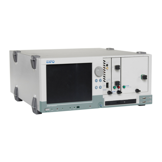
Introducing the IQS-600 Integrated Qualification System Available Models Available Models Below are diagrams to locate the components on your controller and expansion units. IQS-605P-HS Controller Unit The front of the IQS-605P-HS controller unit is where you perform basic operations such as turning your unit on or off, consulting LED indicators, and using data-related peripherals (for example: the USB ports). - Page 12 BNC synchronization port Parallel (printer) port Interlock ground terminals (2) socket Main power switch Interlock ground Monitor port PS/2 mouse port terminals (2) PS/2 keyboard port USB ports (4) EXFO Bus Out port Serial port Control Out port Audio ports (3) IQS-600...
- Page 13 Introducing the IQS-600 Integrated Qualification System Available Models IQS-610P-HS Controller Unit The front of the IQS-610P-HS controller unit is where you perform basic operations such as turning your unit on or off, consulting LED indicators and using data-related peripherals (for example: the USB ports and the DVD-RW drive).
- Page 14 Interlock ground terminals (2) Parallel (printer) port AC socket Main power switch PS/2 mouse port Monitor port Interlock ground terminals (2) PS/2 keyboard port USB ports (4) EXFO Bus Out port Control Out port Serial port Audio ports (3) IQS-600...
- Page 15 Introducing the IQS-600 Integrated Qualification System Available Models IQS-610E-HS Expansion Unit The front of the IQS-610E-HS expansion unit is where you perform basic operations such as turning your unit on or off and consulting LED indicators. Position display indicators Module connector pins On/Off button The back of the IQS-610E-HS expansion unit is where you find the power outlets and connectors to link your expansion units to your controller unit.
-
Page 16: Understanding The Leds
Introducing the IQS-600 Integrated Qualification System Understanding the LEDs Understanding the LEDs The LEDs on your Integrated Qualification System help you determine the current status of your unit. IQS-605P-HS Alarm indicator LED Lock LED Interlock LED When lit on the controller unit, it When lit, the unit is in When lit, it indicates that indicates a problem. - Page 17 Introducing the IQS-600 Integrated Qualification System Understanding the LEDs IQS-610P-HS Interlock LED When lit, it indicates that the Interlock is open (no current is passing through) and that the lasers present in your unit are deactivated. Remote LED When lit, the unit is in Remote mode and the keyboard and mouse are disabled.
-
Page 18: Understanding The Hardware Buttons And Selection Dial (Iqs-605P-Hs)
Introducing the IQS-600 Integrated Qualification System Understanding the Hardware Buttons and Selection Dial (IQS-605P-HS) Understanding the Hardware Buttons and Selection Dial (IQS-605P-HS) The hardware buttons and selection dial on your Integrated Qualification System allow you to perform various tasks. Selection Dial Turn it to scroll up or down in lists, or to move slider. -
Page 19: Locating Integrated Qualification System Synchronization Ports
IQS-600 Integrated Qualification System. The ports located at the back of the unit are reserved for future use only. BNC synchronization port Trigger input/output Control In/Out ports Used to connect specific EXFO units together. Reserved for EXFO. Integrated Qualification System... -
Page 20: Dual Hard Disk Drive
To retrofit your IQS-600 with this option, return your unit to EXFO. Windows will notify you of any malfunction with your RAID 1 hard drive. Should this happen, your data is no longer protected from a single hard drive failure. Contact EXFO’s Technical Support. IQS-600... -
Page 21: Conventions
Introducing the IQS-600 Integrated Qualification System Conventions Conventions Before using the product described in this guide, you should understand the following conventions: ARNING Indicates a potentially hazardous situation which, if not avoided, could result in death or serious injury. Do not proceed unless you understand and meet the required conditions. -
Page 23: Safety Information
Safety Information ARNING Do not install or terminate fibers while a light source is active. Never look directly into a live fiber and ensure that your eyes are protected at all times. ARNING The use of controls, adjustments and procedures, namely for operation and maintenance, other than those specified herein may result in hazardous radiation exposure or impair the protection provided by this unit. -
Page 24: Electrical Safety Information
Safety Information Electrical Safety Information Electrical Safety Information This unit uses an international safety standard three-wire power cable. This cable serves as a ground when connected to an appropriate AC power outlet. Note: If you need to ensure that the unit is completely turned off, disconnect the power cable. - Page 25 Safety Information Electrical Safety Information The color coding used in the electric cable depends on the cable. New plugs should meet the local safety requirements and include: adequate load-carrying capacity ground connection cable clamp ARNING Use this unit indoors only. ...
- Page 26 Safety Information Electrical Safety Information Equipment Ratings Temperature Operation 0 °C to 40 °C (32 °F to 104 °F) Storage –40 °C to 70 °C (–40 °F to 158 °F) Relative humidity 0 % to 80 % non-condensing Maximum operation altitude 2000 m (6562 ft) Pollution degree...
-
Page 27: Other Safety Symbols On Your Unit
Safety Information Other Safety Symbols on Your Unit Other Safety Symbols on Your Unit One or more of the following symbols may also appear on your unit. Symbol Meaning Direct current Alternating current The unit is equipped with an earth (ground) terminal. The unit is equipped with a protective conductor terminal. -
Page 29: Getting Started With Your Integrated Qualification System
Getting Started with Your Integrated Qualification System You can either use your IQS-600 Integrated Qualification System as a benchtop unit, or you can install your units in a rackmount. AUTION If you are using your Integrated Qualification System as a benchtop unit, do not turn it on its side. -
Page 30: Installing Your Controller And Expansion Units In A Rackmount
Getting Started with Your Integrated Qualification System Installing Your Controller and Expansion Units in a Rackmount Installing Your Controller and Expansion Units in a Rackmount Your controller and expansion units were designed to be installed in 19-inch rackmounts only. They will not fit into 23-inch racks. Each unit has a side fan and a rear cooling fan. - Page 31 Getting Started with Your Integrated Qualification System Installing Your Controller and Expansion Units in a Rackmount To prepare your unit for rackmount use: 1. Ensure that your unit is turned off. 2. Remove the bumpers of your controller unit by unscrewing the top and bottom screws.
- Page 32 Getting Started with Your Integrated Qualification System Installing Your Controller and Expansion Units in a Rackmount 3. Assemble the rackmount kit panels using the supplied screws. The screws used for the bumpers will not work to secure the rackmount kit panels. You must use the screws supplied with the kit. IQS-600 unit Rackmount screws Rackmount screws...
- Page 33 Getting Started with Your Integrated Qualification System Installing Your Controller and Expansion Units in a Rackmount 4. Insert the rackmounted unit into the cabinet as shown below and secure it in place using the hardware supplied with the rack. 5. Repeat steps 1 through 3 for each unit being installed in the rackmount. If you want to move a unit forward or backward in the rackmount, untighten the screws on each side of the rackmount kit slightly and slide the unit forward or backward.
-
Page 34: Connecting One Or More Expansion Units To A Controller Unit
Getting Started with Your Integrated Qualification System Connecting One or More Expansion Units to a Controller Unit Connecting One or More Expansion Units to a Controller Unit It is possible to connect expansion units to your controller unit. You can either stack your units on a desk or install them in a rackmount (see Installing Your Controller and Expansion Units in a Rackmount on page 22 for instructions). - Page 35 Connecting One or More Expansion Units to a Controller Unit To connect an Expansion Unit to a Controller Unit: 1. Connect the provided cable to the EXFO Bus Out port located at the back of your controller unit. EXFO controller Bus Out port...
- Page 36 Getting Started with Your Integrated Qualification System Connecting One or More Expansion Units to a Controller Unit 2. Connect the other end of the cable to the EXFO Bus In port located at the back of your expansion unit. EXFO expansion unit Bus Out port...
- Page 37 Connecting One or More Expansion Units to a Controller Unit 3. To connect additional IQS-610E-HS expansion units to your system, use another cable to connect the EXFO Bus Out port of the first unit to the EXFO Bus In port of the second unit.
-
Page 38: Inserting And Removing Test Modules
Never insert or remove a module while the controller unit and its expansion units are turned on. This will result in immediate and irreparable damage to both the module and unit. AUTION To avoid damaging your unit, use it only with modules approved by EXFO. IQS-600... - Page 39 Getting Started with Your Integrated Qualification System Inserting and Removing Test Modules To insert a module into the controller or expansion unit: 1. Exit IQS Manager and turn off all your units. 2. Remove the protective cover from the desired unused module slot. 2a.
- Page 40 Getting Started with Your Integrated Qualification System Inserting and Removing Test Modules 4. Insert the protruding edges of the module into the grooves of the unit’s module slot. Protruding edges (right side of module) Retaining screw knob Retaining screw 5. Push the module all the way to the back of the slot, until the retaining screw makes contact with the unit casing.
- Page 41 Getting Started with Your Integrated Qualification System Inserting and Removing Test Modules The module is correctly inserted when its front panel is flush with the front panel of the controller or expansion unit. When you turn on the controller unit, the startup sequence will automatically detect your module.
- Page 42 AUTION Failure to reinstall protective covers over empty slots will result in ventilation problems. Since IQ modules do not have retaining screw knobs to help you remove them, EXFO provided you with a special tool to facilitate the operation. IQS-600...
- Page 43 Getting Started with Your Integrated Qualification System Inserting and Removing Test Modules To remove IQ modules: 1. Slide the tool’s end between the module front panel and the unit. 2. Using the bumper as the pivot point, push down the tool to release the module.
-
Page 44: Safeguarding Units With The Interlock
Getting Started with Your Integrated Qualification System Safeguarding Units with the Interlock Safeguarding Units with the Interlock EXFO’s more powerful and potentially harmful modules, such as laser sources, are equipped with an interlock system that prevents accidental power ups. If your module is equipped with an interlock system, you might have to link the terminals, located at the back of your IQS-610P-HS controller unit, with the provided connectors. - Page 45 Getting Started with Your Integrated Qualification System Safeguarding Units with the Interlock AUTION The Interlock ground is NOT intended to ground the whole unit. It is used for the interlock cable shielding connection only. If you use modules featuring an interlock, these terminals must communicate, whether it is directly or via the external security device.
-
Page 46: Turning The Integrated Qualification System On And Off
Getting Started with Your Integrated Qualification System Turning the Integrated Qualification System On and Off Turning the Integrated Qualification System On and Off AUTION If the controller unit is stored at a temperature outside of the specified operating temperature range, let the controller unit reach operating temperature before turning it on. -
Page 47: Configuring Your Unit At First Startup
During the configuration process, you will also be asked to read and accept the Microsoft end-user license agreement (EULA). Once the configuration is complete in Windows, an EXFO wizard will be displayed, allowing you to read the user documentation for important safety information, and to read and accept the EULA related to your unit and instruments. - Page 48 Getting Started with Your Integrated Qualification System Configuring Your Unit At First Startup 4. When the EXFO wizard is displayed, follow the on-screen instructions. 5. Click Finish to close the wizard and start working. IQS-600...
-
Page 49: Working With Windows 8.1 Pro
Getting Started with Your Integrated Qualification System Working with Windows 8.1 Pro Working with Windows 8.1 Pro If you are not familiar with Windows 8.1 Pro, you may want to visit Microsoft Web site for tutorials as well as detailed information on the features and concepts brought by this operating system. - Page 50 Getting Started with Your Integrated Qualification System Working with Windows 8.1 Pro Here is an overview of the gestures that you may use the most with your IQS-605P unit. Tap and double-tap: Equivalent of a click and double-click with a ...
-
Page 51: Using The On-Screen (Virtual) Keyboards
Getting Started with Your Integrated Qualification System Using the On-Screen (Virtual) Keyboards Using the On-Screen (Virtual) Keyboards Whenever you need to enter alphanumeric data, you can either use the keyboard that is integrated to IQS Manager (for legacy applications inside IQS Manager), or the Windows on-screen keyboard (for applications inside IQS Manager or in Windows). - Page 52 Getting Started with Your Integrated Qualification System Using the On-Screen (Virtual) Keyboards To activate the IQS Manager on-screen keyboard: 1. In the main window, select the Utilities function tab, then the System tab. 2. Click the Settings button. 3. Under Keyboard, select the Use On-Screen Keyboard option box. The next time you need to enter data, a keyboard appears and you can type using your mouse.
- Page 53 Getting Started with Your Integrated Qualification System Using the On-Screen (Virtual) Keyboards To select the keyboard type: 1. In the main window, select the Utilities function tab, then the System tab. 2. Click the Settings button. 3. Under Keyboard, use the up and down arrow buttons to select your keyboard type in the Keyboard box.
-
Page 54: Installing Or Upgrading The Applications
Getting Started with Your Integrated Qualification System Installing or Upgrading the Applications Installing or Upgrading the Applications All the necessary applications have been preinstalled and configured at the factory. However, you may have to upgrade some applications when new versions become available or to reinstall them. Note: Only administrator-level users can install software under Windows. - Page 55 Getting Started with Your Integrated Qualification System Installing or Upgrading the Applications To update or reinstall Update Manager: 1. If necessary, retrieve the desired installation files from the Internet. If you do not intend to download files directly on your unit, connect a USB memory key to one of the USB ports of the computer and copy the installation files to this USB key.
- Page 56 Getting Started with Your Integrated Qualification System Installing or Upgrading the Applications To install or upgrade the applications: 1. If necessary, retrieve the desired installation files from the Internet. If you do not intend to download files directly on your unit, connect a USB memory key to one of the USB ports of the computer and copy the installation files to this USB key.
-
Page 57: Activating Software Options
In all other cases, you can follow the instructions presented in this section. Before being able to activate options, you need to contact EXFO with the following information: Purchase order number of the newly purchased options ... - Page 58 Getting Started with Your Integrated Qualification System Activating Software Options To activate the options for your unit: 1. Connect a USB memory key to one of the USB ports of your computer. 2. Copy the key file to the USB memory key. 3.
- Page 59 Getting Started with Your Integrated Qualification System Activating Software Options 6. In the Platform Options tab, use the Browse button to locate the key file that you want to use. 7. Click Activate. The option indicator will turn into a green check mark to confirm that the option is now active.
- Page 60 Getting Started with Your Integrated Qualification System Activating Software Options To activate software options for your module: 1. Connect a USB memory key to one of the USB ports of your computer. 2. Copy the key file to the USB memory key. 3.
-
Page 61: Protecting Your Unit With An Antivirus Software
Getting Started with Your Integrated Qualification System Protecting your Unit with an Antivirus Software 6. In the Module Options tab, use the Browse button to locate the key file that you want to use. 7. Click Activate. The option indicator will turn into a green check mark to confirm that the option is now active. -
Page 62: Accessing Iqs Manager
To access IQS Manager when in the Windows environment: Click the IQS Manager icon on your desktop. Click the Windows button ( ), then under EXFO, select IQS Manager. The main window is used to control your platform:... -
Page 63: Exiting Iqs Manager
Getting Started with Your Integrated Qualification System Exiting IQS Manager Exiting IQS Manager To exit IQS Manager: 1. Click the Exit button, located on the lower right-hand side of the main window. 2. Select the appropriate option among the three choices below: Exit IQS Manager: to close IQS Manager and return to Windows. -
Page 64: Installing Exfo Labview Drivers
Getting Started with Your Integrated Qualification System Installing EXFO LabVIEW Drivers Installing EXFO LabVIEW Drivers Before being able to work with EXFO LabVIEW drivers, you must install the following elements on your computer or on your IQS-600 Integrated Qualification System: National Instruments LabVIEW software and the corresponding ... - Page 65 Getting Started with Your Integrated Qualification System Installing EXFO LabVIEW Drivers To install the LabVIEW software: 1. Insert the LabVIEW CD in the CD-ROM drive of your unit or computer. 2. The installation process should start automatically. If not, or if you have...
- Page 66 Getting Started with Your Integrated Qualification System Installing EXFO LabVIEW Drivers To install the EXFO LabVIEW drivers: 1. Insert the installation CD in the CD-ROM drive if needed, unless you have downloaded the drivers from the National Instruments Web site.
-
Page 67: Connecting An External Monitor
Getting Started with Your Integrated Qualification System Connecting an External Monitor Connecting an External Monitor A controller unit can be connected to an external monitor. Connect your monitor to the standard computer connector located at the back of the unit. Monitor port Note: Use the Windows Control Panel to configure the display settings of your external monitor. - Page 68 Getting Started with Your Integrated Qualification System Connecting an External Monitor AUTION Do not put the monitor directly on the front part of your units. This would press on the front opening, thus preventing you from inserting or removing modules correctly. Ensure that the monitor: is at least 8 inches away from the front of the unit;...
-
Page 69: Connecting An External Keyboard
Getting Started with Your Integrated Qualification System Connecting an External Keyboard Connecting an External Keyboard Your IQS-600 Integrated Qualification System can be used with either a USB or a PS/2 keyboard. To connect a keyboard to the unit: Use any of the USB ports located both at the front and back of the unit. Use the PS/2 keyboard port located at the back of the unit. -
Page 70: Connecting A Mouse
Getting Started with Your Integrated Qualification System Connecting a Mouse Connecting a Mouse Your IQS-600 Integrated Qualification System can be used with either a USB or PS/2 mouse. To connect a mouse to the unit: Use any of the USB ports located both at the front and back of the unit. Use the PS/2 mouse port located at the back of the unit. -
Page 71: Connecting A Tape, Cd, Or Dvd Player
Getting Started with Your Integrated Qualification System Connecting a Tape, CD, or DVD Player Connecting a Tape, CD, or DVD Player Your IQS-600 Integrated Qualification System can be used with an external tape, CD, or DVD player. To connect a tape, CD, or DVD player to the unit: Use the Line In port located at the back of the unit. -
Page 72: Connecting A Headset Or A Speaker
Getting Started with Your Integrated Qualification System Connecting a Headset or a Speaker Connecting a Headset or a Speaker Your IQS-600 Integrated Qualification System can be used with either a headset or speaker. To connect a headset or speaker to the unit: Use the Line Out port located at the back of the unit. -
Page 73: Connecting A Microphone
Getting Started with Your Integrated Qualification System Connecting a Microphone Connecting a Microphone Your IQS-600 Integrated Qualification System can be used with a microphone. To connect a microphone to the unit: Use the microphone port located at the back of the unit. Microphone Microphone Integrated Qualification System... -
Page 74: Connecting A Printer
Getting Started with Your Integrated Qualification System Connecting a Printer Connecting a Printer Your IQS-600 Integrated Qualification System can be used with a printer. To connect a printer to the unit: Use any of the USB ports located both at the front and back of the unit. Use the parallel port located at the back of the unit. -
Page 75: Setting Up Your Integrated Qualification System
Setting Up Your Integrated Qualification System Calibrating Your Touchscreen (IQS-605P-HS) The touchscreen simplifies and accelerates testing procedures by providing immediate access to commands. It detects the position of the finger or any other blunt pointing device used to activate a command, a function, or a button. -
Page 76: Adjusting Microphone And Speaker Volume
Setting Up Your Integrated Qualification System Adjusting Microphone and Speaker Volume To calibrate your touchscreen: 1. From the front panel of the unit, press the button to show the taskbar (IQS-605P units). 2. Point the lower left corner of the screen, and then click the Start button 3. -
Page 77: Changing The Backlight Level (Iqs-605P-Hs)
Setting Up Your Integrated Qualification System Changing the Backlight Level (IQS-605P-HS) 3. Move the slider until the sound level is to your liking. Note: You can also access the sound level slider by using the icon from the taskbar. Changing the Backlight Level (IQS-605P-HS) The backlight has four brightness levels: Off, Low, Medium, and High. -
Page 78: Deactivating The Led Display
Setting Up Your Integrated Qualification System Deactivating the LED Display Deactivating the LED Display Note: This feature is not available in offline mode. Your testing environment may require total darkness and you do not want any LED or light activity that could compromise your test results. Note: The backlight does not automatically turn off. -
Page 79: Selecting The Language Of Operation
Setting Up Your Integrated Qualification System Selecting the Language of Operation Selecting the Language of Operation You may display the user interface in one of the available languages. If you select another language than those available for your platform, English will be used. - Page 80 Setting Up Your Integrated Qualification System Selecting the Language of Operation 3. Select the desired language from the list. Note: If the language you want is not in the list of available languages, you must install the corresponding language pack through the Internet. 4.
- Page 81 Setting Up Your Integrated Qualification System Selecting the Language of Operation 5. If you want to select another keyboard layout than the one that has been added by default, proceed as follows: 5a. Under Input method, click Add input method. Integrated Qualification System...
- Page 82 Setting Up Your Integrated Qualification System Selecting the Language of Operation 5b. Select the desired keyboard layout, then click Add. IQS-600...
- Page 83 Setting Up Your Integrated Qualification System Selecting the Language of Operation 6. Under Windows display language, click Make this the primary language. 7. When the application prompts you to log off, select Log off now. 8. Once you see the lock screen, log in your user account. The new language is now selected and you are able to switch from one input language to another.
- Page 84 Setting Up Your Integrated Qualification System Selecting the Language of Operation To download language packs: 1. Ensure that your unit has access to the Internet. 2. From the Windows Desktop, right-click on the Start ( ) button, then select Control Panel. 3.
- Page 85 Setting Up Your Integrated Qualification System Selecting the Language of Operation 4. Click Add a language. 5. Browse the list of languages, and then select the one that you want to use. 6. Click Open to access the list of sub-languages. Integrated Qualification System...
- Page 86 Setting Up Your Integrated Qualification System Selecting the Language of Operation 7. Select the desired sub-language, and then click Add. IQS-600...
- Page 87 Setting Up Your Integrated Qualification System Selecting the Language of Operation 8. Select the desired language from the list. 9. Click Options. Integrated Qualification System...
- Page 88 Setting Up Your Integrated Qualification System Selecting the Language of Operation 10. Click Download and install language pack. 11. When the application prompts you to allow the installation, Click Yes. The installation may take a few minutes. 12. When the installation is complete, restart your unit. To switch from one input language to another: 1.
-
Page 89: Setting Date And Time Formats
Setting Up Your Integrated Qualification System Setting Date and Time Formats Setting Date and Time Formats By default, the dates (short and long) and time are displayed in the formats associated with the global language format (locale). The time can be expressed with a 12- or 24-hour notation. - Page 90 Setting Up Your Integrated Qualification System Setting Date and Time Formats 3. Refine the settings according to your needs. 4. Click Apply to confirm, and then OK to close the window. The values are taken into account immediately. IQS-600...
-
Page 91: Adjusting The Date, Time And Time Zone
Setting Up Your Integrated Qualification System Adjusting the Date, Time and Time Zone Adjusting the Date, Time and Time Zone Note: Only administrator-level users can adjust the date and time. All users can modify the time zone. The current date and time are displayed at the bottom of the main window. When saving results, the unit also saves the corresponding date and time. -
Page 92: Selecting The Startup Interface
Setting Up Your Integrated Qualification System Selecting the Startup Interface Selecting the Startup Interface You can select whether or not IQS Manager automatically starts when you turn the unit on. To select the startup interface: 1. Select the Utilities function tab, and then select the System tab. 2. -
Page 93: Customizing Access Levels
Setting Up Your Integrated Qualification System Customizing Access Levels Customizing Access Levels You cannot set passwords in IQS Manager itself. It uses the same security levels and accesses as Windows. This means that if you are logged in Windows as an Administrator, you have access to everything on IQS Manager. - Page 94 Setting Up Your Integrated Qualification System Customizing Access Levels To customize access levels: 1. In the main window, select the Utilities function tab, then the System tab. 2. Click Passwords. 3. Ensure that Apply Security Access Control selected. 4. Click the tab of the user level for which you want to set accesses. 5.
-
Page 95: Setting Up Auto Logon For Windows
Setting Up Your Integrated Qualification System Setting Up Auto Logon for Windows Setting Up Auto Logon for Windows Note: Only administrator-level users can enable or disable the automatic logon feature. You can set Windows to automatically log on when you start your unit (no need to select a user and enter a password). - Page 96 Setting Up Your Integrated Qualification System Setting Up Auto Logon for Windows To automatically log on to Windows upon startup: 1. Start Windows. 2. On the taskbar of the computer, click the start ( ) button, then under Windows System, select Run. 3.
-
Page 97: Setting Communication Parameters
Setting Up Your Integrated Qualification System Setting Communication Parameters 5. Select the User name box, type the user name that was displayed on the start menu in step 1. If you normally type a password to log on, type your password in both the Password and Confirm Password boxes. -
Page 98: Adjusting The Fan Speed
Setting Up Your Integrated Qualification System Adjusting the Fan Speed Adjusting the Fan Speed By default, the fan speed of the IQS-600 controller unit and expansion units is set to maximum. If you prefer, the application can also adjust the fan speed to a safe minimum. - Page 99 Setting Up Your Integrated Qualification System Adjusting the Fan Speed To adjust the fan speed: 1. In the main window, select the Utilities function tab. 2. Select the Tools tab, then Fan Speed Setup. 3. Select the desired option. Current fan speed (indicated only if different from full speed) 4.
-
Page 100: Saving And Opening Configurations
Setting Up Your Integrated Qualification System Saving and Opening Configurations Saving and Opening Configurations It is possible to save as many configurations as you want. This is particularly useful if users need to work with different configurations. The configuration file includes: active modules ... - Page 101 Setting Up Your Integrated Qualification System Saving and Opening Configurations To load a configuration: 1. Select the Utilities function tab, and then select the System tab. 2. Click Load Configuration. 3. In the list at the top of the Open Configuration dialog box, select the configuration to use and click Open.
-
Page 102: Saving The Configuration On Exiting
Setting Up Your Integrated Qualification System Saving the Configuration on Exiting Saving the Configuration on Exiting IQS Manager offers you the possibility of saving your configuration as you exit. This allows you to continue where you left off when starting a new session. -
Page 103: Changing Unit And Module Identification
Setting Up Your Integrated Qualification System Changing Unit and Module Identification Changing Unit and Module Identification Note: This feature is not available in Offline mode. You can change the identification of your units and modules for easier hardware management. To change the identification for your unit or module: 1. - Page 104 Setting Up Your Integrated Qualification System Changing Unit and Module Identification 3. Click the unit or module you want to configure (it will turn white to indicate that it is selected). 4. Change the unit or module name and number as desired, using the corresponding fields.
-
Page 105: Reverting To Factory Settings
Setting Up Your Integrated Qualification System Reverting to Factory Settings Reverting to Factory Settings You might need to revert to the factory settings, such as keyboard configuration or startup interface. MPORTANT This action cannot be undone. Note: You can only use the Revert to Factory function if you are logged on as an Administrator level user. -
Page 107: Using The Iqs Manager Interface
Using the IQS Manager Interface This section helps you to work with the IQS Manager interface. Accessing Current Modules Note: This feature is not available in Offline mode. If you did not select the Save Configuration on Exit option on the Systems tab of the Settings dialog box, the Current Modules function tab appears each time you start a new IQS Manager session. - Page 108 Using the IQS Manager Interface Accessing Current Modules The name, current status and serial number of each module installed on the unit you have selected in the system tree appear besides the module’s icon. A green icon means that the module is ready for you to use. ...
- Page 109 Using the IQS Manager Interface Accessing Current Modules If you are currently in Remote mode and wish to revert to Local mode, press on the LOCAL button on the front of your controller unit. This button is ineffective if you are in Lockout mode. For detailed instructions on how to start the single-module application related to your specific IQS module, refer to the corresponding user guide.
-
Page 110: Accessing Integrated Applications
Using the IQS Manager Interface Accessing Integrated Applications Accessing Integrated Applications The Integrated Applications function tab is where you can start applications requiring or affecting more than one module at the same time. The multimodule applications allow you to control several modules of the same kind through a single interface. -
Page 111: Working On Test Results (Offline Mode)
Using the IQS Manager Interface Working on Test Results (Offline Mode) Working on Test Results (Offline Mode) Your IQS-600 Integrated Qualification System includes an application for data processing. This can be accessed through the Work on Results (Offline) function tab. It allows you to perform jobs on acquisitions or tests that have already been taken. -
Page 112: Creating An Integrated Data Display
Using the IQS Manager Interface Creating an Integrated Data Display Creating an Integrated Data Display Note: This feature is not available in Offline mode. When using one or more IQS modules in a test setup, you can view module data and status using monitor windows in IQS Manager. To do so, select the Monitors function tab. - Page 113 Using the IQS Manager Interface Creating an Integrated Data Display To move monitor windows: 1. To select the monitor window you want to move, click once on its title bar. The window title bar changes color to indicate that it is selected. 2.
-
Page 114: Viewing Pdf Files
Using the IQS Manager Interface Viewing PDF Files Viewing PDF Files You can view PDF files directly from your unit using the SumatraPDF reader. For more information on the available features for this reader, refer to the SumatraPDF online help. To view PDF files: 1. -
Page 115: Locating Units
Using the IQS Manager Interface Locating Units Locating Units Note: This feature is not available in Offline mode. Since you can connect many IQS-610E-HS expansion units to your IQS-610P-HS controller unit, it may become difficult to find a particular module. To help you locate units, click Locate Unit in the Current Modules function tab. -
Page 116: Accessing Utilities From Iqs Manager
Using the IQS Manager Interface Accessing Utilities from IQS Manager Accessing Utilities from IQS Manager Various utilities are located on the Utilities function tab. Accessing Utilities from Windows Your unit comes with free tools such as Wireshark to help you troubleshoot networks. -
Page 117: Accessing Your Iqs-600 Remotely
Accessing your IQS-600 Remotely You can access your unit remotely from a computer using either the Remote Desktop Connection or TightVNC Client applications. This could be particularly useful if you do not intend to perform automation tasks on your platform. If you want to perform automation tasks on your platform and modules, see Using IQS Products in an Automated Test Environment on page 175. -
Page 118: Working With Remote Desktop
Accessing your IQS-600 Remotely Working with Remote Desktop Working with Remote Desktop By default, all the accounts with administrator rights can use Remote Desktop. If you want accounts with limited rights to be able to use Remote Desktop as well, you must specifically grant them access. You can also configure the unit to prevent users from accessing it remotely. - Page 119 Accessing your IQS-600 Remotely Working with Remote Desktop To access your IQS-600 remotely: 1. Connect both the computer and your unit to the same network and make sure they can “see” each other as network restrictions might prevent them from communicating. 2.
-
Page 120: Allowing User With Limited Accounts To Use Remote Desktop
Accessing your IQS-600 Remotely Allowing User with Limited Accounts to Use Remote Desktop Allowing User with Limited Accounts to Use Remote Desktop By default, only the accounts with administrator rights can use Remote Desktop. However, you can assign extra user rights to accounts with limited rights so that they can also use Remote Desktop. - Page 121 Accessing your IQS-600 Remotely Allowing User with Limited Accounts to Use Remote Desktop 3. Under System, select Allow remote access. 4. Under Remote Desktop, select Allow remote connections to this computer. 5. Click Select Users. Integrated Qualification System...
- Page 122 Accessing your IQS-600 Remotely Allowing User with Limited Accounts to Use Remote Desktop 6. From the Remote Desktop Users dialog box, click Add. 7. From the Select Users dialog box, click Advanced. IQS-600...
- Page 123 Accessing your IQS-600 Remotely Allowing User with Limited Accounts to Use Remote Desktop 8. Click Find Now to let the system find and display the list of users. 9. Select the user to which you want to grant access rights, and then click Integrated Qualification System...
- Page 124 Accessing your IQS-600 Remotely Allowing User with Limited Accounts to Use Remote Desktop 10. From the list of users, select the user that you have just added, and then click OK. 11. Repeat steps 8 to 10 with all the users to which you want to grant access rights.
- Page 125 Accessing your IQS-600 Remotely Allowing User with Limited Accounts to Use Remote Desktop Restarting or Turning Off Your Unit While Working with Remote Desktop In some cases, you may need to restart or shutdown your unit while you are controlling it remotely. To restart or turn off your unit with Remote Desktop: 1.
-
Page 126: Working With Tightvnc
Accessing your IQS-600 Remotely Working with TightVNC Working with TightVNC The control of your unit with TightVNC requires the TightVNC Server (already installed on your unit) and the TightVNC Client Viewer (that you must install on your computer). The first time you start the TightVNC Server on your unit, the application will prompt you to define passwords. - Page 127 Accessing your IQS-600 Remotely Working with TightVNC Configuring the TightVNC Server The TightVNC Server is already installed on your unit. You must configure passwords before establishing a connection between a computer and your unit. To configure the TightVNC Server: 1. On the taskbar of the computer, click the start ( ) button, then under Tight VNC, select Run TightVNC Server.
- Page 128 Accessing your IQS-600 Remotely Working with TightVNC 4. To require a password from both the primary users and the view-only users, click Set, then enter and confirm the appropriate passwords. Note: The two passwords are independent of each other. They do not have to be identical.
- Page 129 However, if you need to install it on another computer or unit, download it from the TightVNC Web site. Note: EXFO recommends to make a shortcut on your desktop once your TightVNC Viewer is downloaded.
- Page 130 Accessing your IQS-600 Remotely Working with TightVNC Using a Web Server as a Viewer You can access to the TightVNC Server via a Web browser such as Microsoft Internet Explorer. The TightVNC server contains a small Web server. When you connect to it by using your Internet search engine, the Java applet for the viewer is downloaded automatically.
- Page 131 Accessing your IQS-600 Remotely Working with TightVNC To connect remotely by using a Web browser: 1. From the computer Web browser, enter an appropriate IP address, following the example below: colon http://172.16.76.20:5800 TCP port IP Address 2. In the VNC Authentication dialog box, in the Password box, type your password.
-
Page 133: Preparing For Automation
Preparing for Automation The IQS-600 Integrated Qualification System was designed to meet the requirements of automation and to facilitate its integration with your test environment. An IQS-600 Integrated Qualification System always requires a controller unit (IQS-605P-HS or IQS-610P-HS) to drive the instruments (optical as well as Transport and Datacom). - Page 134 Preparing for Automation EXFO supplies commands that follow the guidelines determined by the SCPI consortium and LabVIEW drivers for all available instruments. EXFO also supplies COM properties and events allowing you to build your own application The instruments can be controlled either locally or remotely via...
- Page 135 Preparing for Automation Control Technology Characteristics Local ActiveX (COM) Allows you to develop an application that will run locally on the IQS controller unit within Windows Best approach when speed is your top priority (no physical connection that slows down the process) Supported by most development software ...
- Page 136 Preparing for Automation Control Technology Characteristics Remote Telnet (Ethernet, IQS controller unit can be directly connected to a TCP/IP) Local Area Network (LAN) or Wide Area Network (WAN) via its 10/100/1000 Base-T interface No need for a GPIB card ...
-
Page 137: Configuring Your Integrated Qualification System For Working With Gpib
Do not remove the GPIB card from the IQS controller unit. MPORTANT If you have not previously selected the GPIB option and now wish to purchase a GPIB card, contact EXFO. Purchasing your new GPIB card from EXFO will ensure compatibility with your IQS-600. Integrated Qualification System... - Page 138 Preparing for Automation Configuring Your Integrated Qualification System for Working with GPIB To install the GPIB software and drivers for your GPIB card: 1. Go on the National Instrument Web site at the following location http://www.ni.com/download/ni-488.2-3.1.2/4360/en/, and download the installation kit. 2.
- Page 139 4. In the installation wizard Welcome window, select Install Software. Confirm that you want to proceed with the installation by clicking Yes. 5. Confirm the location where the software will be installed. EXFO recommends that you do not change the location. Click Next to continue.
- Page 140 Preparing for Automation Configuring Your Integrated Qualification System for Working with GPIB 6. Confirm which items will be installed on your unit. EXFO recommends that you do not change the list. Click Next to continue. 7. If you want to look for updates for your software, you can have the wizard search the National Instruments site at this point.
- Page 141 Preparing for Automation Configuring Your Integrated Qualification System for Working with GPIB 8. Read the license agreement, then confirm that you accept the terms; click Next to continue. 9. Review which items will be installed or updated, then click Next to start the installation.
- Page 142 Preparing for Automation Configuring Your Integrated Qualification System for Working with GPIB 10. If you already have a user profile at National Instruments, you can use it to register your product directly from the Web. Otherwise, select the option to register your product without an NI profile. Click Next to continue.
- Page 143 Preparing for Automation Configuring Your Integrated Qualification System for Working with GPIB 12. Select which items you want registered. Click Register to confirm your choice. 13. Once the registration is complete, click Finish to close the wizard. Integrated Qualification System...
-
Page 144: Preparing Hardware For Gpib Control
If you intend to use GPIB to remotely control your instruments, your controller must have been equipped with the optional GPIB card. To ensure the optimum efficiency of your system, EXFO recommends that you follow these restrictions: For the IEEE 488.1 protocol: Maximum of 15 devices physically connected to each GPIB bus. - Page 145 Preparing for Automation Preparing Hardware for GPIB Control The IQS-600 Integrated Qualification System configuration complies with the IEEE 488.1 (also known as IEC60625.1) and the IEEE 488.2 (also known as IEC60625.2) standards to the extent shown in the following table. Mnemonic Function SHE1...
-
Page 146: Linking Units With The Gpib Port
Preparing for Automation Linking Units with the GPIB Port Linking Units with the GPIB Port If your IQS-600 Integrated Qualification System is equipped with a GPIB card, use the provided cable to link it to the other unit with which you want to perform remote control. -
Page 147: Linking Units With The Serial Port
Preparing for Automation Linking Units with the Serial Port Linking Units with the Serial Port Your IQS-600 Integrated Qualification System is equipped with a serial (RS-232) port to send and receive data. Refer to the Microsoft Windows documentation for information about serial port settings and possibilities. Getting Optimum Performance from Your Integrated Qualification System Several factors influence the data transfer rate of an IQS controller unit. - Page 148 Preparing for Automation Getting Optimum Performance from Your Integrated Qualification System For information on cabling, see Preparing Hardware for GPIB Control on page 136. Bus timing (GPIB control only): Required if you intend to work with IEEE 488.1, for it affects the handshake rate of this protocol. It indicates the minimum amount of time a GPIB controller waits, once data is placed on the bus, before setting the data valid bus line (DAV) to true.
- Page 149 Preparing for Automation Getting Optimum Performance from Your Integrated Qualification System Output format (GPIB, RS-232, ActiveX and TCP/IP): The IQS controller unitprovides the following output formats for measurement results: ASCii PACKed Generally, the PACKed format allows to pass three to four times more information than the ASCii format for the same transfer rate.
-
Page 150: Changing Communication Settings
Preparing for Automation Changing Communication Settings Changing Communication Settings Communication settings cannot be modified without turning on your IQS-600 Integrated Qualification System and starting IQS Manager. To change communication settings: 1. From the Utilities function tab, select Instrument Control Configuration. 2. - Page 151 Preparing for Automation Changing Communication Settings 3. Under Platform Startup, determine whether your module applications will be started locally or remotely by clicking the corresponding option. If Local mode is selected, you will not be able to send remote commands to your IQS controller or expansion units.
- Page 152 Preparing for Automation Changing Communication Settings 5. According to the communication type you have selected, customize the corresponding parameters as shown below. For GPIB IQS controller and expansion units can have up to four GPIB cards. Default value is GPIB0. The selected address must not already be used by the GPIB bus controller or any other device connected to the GPIB bus.
- Page 153 Preparing for Automation Changing Communication Settings For TCP/IP TCP/IP port 5024—used to connect over Telnet. For information on communicating with TCP/IP over Telnet, see the section pertaining to communication through TCP/IP over Telnet. 6. Click Apply to confirm your changes. 7.
- Page 154 Preparing for Automation Changing Communication Settings To revert to default RS-232 settings: 1. Click the Default RS-232 Settings button. 2. Click Apply to confirm your changes. IQS-600...
-
Page 155: Configuring Dcom Access To Your Unit
DCOM issues. The example presented in the following pages illustrates how to make the EXFO IcSCPIAccess Class component available to all users of a local network under Windows 8.1 Pro. The example provided below is for guidance only; it may not work properly with all networks and interfaces may slightly differ depending on the operating system used. - Page 156 Preparing for Automation Configuring DCOM Access to Your Unit Setting the General Security Parameters Note: To modify the security parameters, you need administrator access rights. To set the general security parameters: 1. Start Windows. 2. From the main window, click the System Settings button. 3.
- Page 157 Preparing for Automation Configuring DCOM Access to Your Unit 8. In the My Computer Properties dialog box, click the COM Security tab. 9. Under Access Permissions, click Edit Limits. Integrated Qualification System...
- Page 158 Preparing for Automation Configuring DCOM Access to Your Unit 10. In the Access Permission dialog box, ensure that the Distributed COM Users group appears in the Group or user names list. 11. Click OK. 12. In the My Computer Properties dialog box, click the COM Security tab.
- Page 159 Preparing for Automation Configuring DCOM Access to Your Unit 13. Under Launch and Activation Permissions, click Edit Limits. Integrated Qualification System...
- Page 160 Preparing for Automation Configuring DCOM Access to Your Unit 14. In the Access Permission dialog box, ensure that the Distributed COM Users group appears in the Group or user names list. You can now allow users to access general DCOM services on your unit. You can either: Add a user to the Distributed COM Users group (refer to Microsoft ...
- Page 161 Preparing for Automation Configuring DCOM Access to Your Unit To add a user explicitly: 1. In the My Computer Properties dialog box, click the COM Security tab. 2. Under Access Permission, click Edit Limits. 3. In the Access Permission dialog box, click Add. Integrated Qualification System...
- Page 162 Preparing for Automation Configuring DCOM Access to Your Unit 4. In the Select Users or Groups dialog box, under Enter the object names to select, type the name of the user to whom you want to give access rights. 5. Click OK. IQS-600...
- Page 163 Preparing for Automation Configuring DCOM Access to Your Unit 6. Confirm the newly added user has remote access permission as follows: 6a. In the Access Permission dialog box, select the name of the new user. 6b. Under Permissions for (new user), ensure Allow is selected for Remote Access.
- Page 164 Preparing for Automation Configuring DCOM Access to Your Unit 9. In the Launch and Activation Permission dialog box, click Add. 10. In the Select Users or Groups dialog box, under Enter the object names to select, type the name of the user to whom you want to give start and activation access rights.
- Page 165 Preparing for Automation Configuring DCOM Access to Your Unit 12. Confirm the newly added user has Remote Launch and Remote Activation permissions as follows: 12a.In the Launch Permission dialog box, select the name of the new user. 12b.Under Permissions for (new user), ensure Allow is selected for both Remote Launch and Remote Activation.
- Page 166 1. From the Component Services window, select: Console Root > Component Services > Computers > My Computer > DCOM Config to show the contents of the DCOM Config folder. 2. From DCOM Config, right-click EXFO KernosHost, and select Properties. 3. Click the General tab.
- Page 167 Preparing for Automation Configuring DCOM Access to Your Unit 4. In the Authentication Level list, select Default. Integrated Qualification System...
- Page 168 Preparing for Automation Configuring DCOM Access to Your Unit 5. In the EXFO KernosHost Properties dialog box, click the Security tab. 6. Under Launch and Activation Permissions, select Customize, and then click Edit to edit the list of allowed users.
- Page 169 Preparing for Automation Configuring DCOM Access to Your Unit 7. In the Launch and Activation Permission dialog box, click Add. 8. In the Select Users or Groups dialog box, under Enter the object names to select, type the name of the user to whom you want to give start and activation permissions for remote access.
- Page 170 Preparing for Automation Configuring DCOM Access to Your Unit 10. In the Launch and Activation Permission dialog box, select a user. 11. To allow this user to start and activate the IQS-600 remotely, select Allow for all four permission choices. 12.
- Page 171 Preparing for Automation Configuring DCOM Access to Your Unit 14. In the EXFO KernosHost Properties dialog box, click the Security tab. 15. Under Access Permissions, select Customize, and click Edit to edit the list of allowed users. MPORTANT Customizing access rights sets both remote AND local permissions.
- Page 172 Preparing for Automation Configuring DCOM Access to Your Unit 17. In the Select Users or Groups dialog box, under Enter the object names to select, type the name of the user to whom you want to give access permissions for remote access. 18.
- Page 173 21. Repeat steps 19 and 20 for each newly added user. 22. Click OK to close the Access Permission dialog box. 23. Click OK to close the EXFO KernosHost Properties dialog box. 24. Restart your IQS-600. The EXFO IcSCPIAccess Class component, located on your IQS-600 Integrated Qualification System, can now be accessed with DCOM.
- Page 174 Enabling DCOM on Client Computer Note: To run DCOMCNFG.EXE, you need Administrator access rights. If you want to subscribe to EXFO IcSCPIAccess Class component events, you need to set security parameters on the client computer. To enable DCOM on the client computer: 1.
- Page 175 Preparing for Automation Configuring DCOM Access to Your Unit 4. Right-click My Computer, and then select Properties. 5. In the My Computer Properties dialog box, click the Default Properties tab. 6. Select Enable Distributed COM on this computer. 7. Under Default Distributed COM Communication Properties, in the Default Authentication Level list, select Connect.
- Page 176 Preparing for Automation Configuring DCOM Access to Your Unit 10. Click the COM Security tab and, under Access Permissions, click Edit Limits. 11. In the Access Permission dialog box, ensure that, for ANONYMOUS LOGON, local and remote accesses are allowed. If ANONYMOUS LOGON is not listed under Group or user names, click Add to add it.
- Page 177 5. From the Component Services window, select: Console Root > Component Services > Computers > My Computer > DCOM Config to show the contents of the DCOM Config folder. 6. From DCOM Config, right-click EXFO KernosHost, and select Properties. Integrated Qualification System...
- Page 178 Preparing for Automation Configuring DCOM Access to Your Unit 7. In the EXFO KernosHost Properties dialog box, click the Security tab. 8. Under Launch and Activation Permissions and Access Permissions, select Use Default. This ensures the EXFO IcSCPIAccess Class component uses the default lists instead of the customized lists.
-
Page 179: Preparing To Control Modules With A Dedicated Application
Preparing for Automation Preparing to Control Modules with a Dedicated Application Preparing to Control Modules with a Dedicated Application Some modules come with a dedicated application designed to control them remotely from a computer. The main characteristic of this application is that it lets another user control the module exactly as if he had it close at hand. - Page 180 Preparing for Automation Preparing to Control Modules with a Dedicated Application To activate or deactivate remote control: 1. From the Utilities function tab, select the System tab. 2. Select Remote Control Configuration. IQS-600...
- Page 181 Preparing for Automation Preparing to Control Modules with a Dedicated Application 3. From the Remote Control Configuration window you will see all the inserted modules. Select the module for which you want to have a remote access. Note: Modules for which remote control is not supported are identified as unrecognized.
- Page 182 Preparing for Automation Preparing to Control Modules with a Dedicated Application 5. Under Description, type a relevant description (test interface ID, for example). Note: You can enter up to 10 characters. The description corresponds to the test interface ID or any other relevant description. 6.
-
Page 183: Using Iqs Products In An Automated Test Environment
Using IQS Products in an Automated Test Environment EXFO supplies commands that follow the guidelines determined by the SCPI consortium and LabVIEW drivers for all available instruments. EXFO also supplies COM properties and events allowing you to build your own application. -
Page 184: Managing The States Of Your Iqs-600 Integrated Qualification System
Using IQS Products in an Automated Test Environment Managing the States of Your IQS-600 Integrated Qualification System Managing the States of Your IQS-600 Integrated Qualification System Your IQS-600 Integrated Qualification System can be in one of the following states: State Characteristics Local Front-panel keys of the IQS controller unitand... - Page 185 Using IQS Products in an Automated Test Environment Managing the States of Your IQS-600 Integrated Qualification System State Characteristics Remote with lockout Front-panel keys of the IQS controller unit and peripherals are not functional except for the power button Return to Local mode only possible via commands ...
- Page 186 Using IQS Products in an Automated Test Environment Managing the States of Your IQS-600 Integrated Qualification System The following diagram shows the possible transitions between the different states. Remote Local Remote Lockout Local Lockout Possible in GPIB if: Possible in ActiveX by setting: The remote interface message (REM) is set The RemoteState property to ...
- Page 187 Using IQS Products in an Automated Test Environment Managing the States of Your IQS-600 Integrated Qualification System Possible in GPIB if: Possible in ActiveX by setting: The local lockout interface message (LLO) is The LockoutState property to set to True. True.
-
Page 188: Message Management
Using IQS Products in an Automated Test Environment Message Management Message Management Each device that is physically connected to the GPIB link has its own input buffer, output queue and error/event queue. These data structures allow storage of incoming messages (single or compound commands that are sent to an instrument), responses from queries, errors and events that may occur. - Page 189 Using IQS Products in an Automated Test Environment Message Management Data structure Characteristics Clearing Except for the string and binary block contents, the following transformations are made on the incoming data: character conversion from lower case to upper case. conversion of “<wsp>”...
- Page 190 Using IQS Products in an Automated Test Environment Message Management Data structure Characteristics Clearing Error/Event queue Consists of a First-In, First-Out The Error/Event queue will (FIFO) data structure. be cleared when: Total storage capacity: 50 errors or Reading all the items it ...
-
Page 191: Standard Status Data Structure
Using IQS Products in an Automated Test Environment Standard Status Data Structure Standard Status Data Structure Each device that is physically connected to the GPIB bus has four status registers with a structure complying with the IEEE 488.2 standard. These registers allow the controller to monitor events and get useful information on the status of the devices it controls. - Page 192 Using IQS Products in an Automated Test Environment Standard Status Data Structure The following table presents a summary of the possible operations on ESR and ESE registers. Register Read Write Clear Use *ESR?. Impossible Use *CLS. to write. Read the register. ...
- Page 193 Using IQS Products in an Automated Test Environment Standard Status Data Structure The following table presents a summary of the possible operations on STB and SRE registers. Register Read Write Clear Use *STB?. Impossible to write; Use *CLS before the register content is sending a query (to Use serial poll (GPIB...
- Page 194 Using IQS Products in an Automated Test Environment Standard Status Data Structure IQS-600...
-
Page 195: Scpi Command Structure
Using IQS Products in an Automated Test Environment SCPI Command Structure SCPI Command Structure The information presented in this section provides an overview of SCPI programming. If you need detailed information, refer to: The International Institute of Electrical and Electronics Engineers. IEEE ... - Page 196 Using IQS Products in an Automated Test Environment SCPI Command Structure The following table shows elements that are commonly used in the commands or queries syntax. Item Meaning Enclose optional keywords or parameters. Do not include square brackets in your program message. [1..n] Indicates that the instrument provides multiple capabilities and that you have to specify which one you want to use.
- Page 197 Using IQS Products in an Automated Test Environment SCPI Command Structure Item Meaning <mnemonic> Element used in the construction of certain data types and program messages. <Upper/lower case alpha> <Upper/lower case alpha> <digit> In the diagram above, “<Upper/lower case alpha>” corresponds to ASCII character codes ...
- Page 198 Using IQS Products in an Automated Test Environment SCPI Command Structure Item Meaning Mandatory to separate the different commands of a program message when more than one command is sent at a time. In this case, it is called <PROGRAM MESSAGE UNIT SEPARATOR>. Also used to separate responses when multiple queries were sent in ...
- Page 199 Using IQS Products in an Automated Test Environment SCPI Command Structure You can build program messages allowing you to send more than one command at a time. Sometimes, you can omit the leading <mnemonic> path to simplify the program messages and speed up the search time (the parser saves the last position in the command tree).
-
Page 200: Consulting Data Types
Using IQS Products in an Automated Test Environment Consulting Data Types Consulting Data Types If you need information about data types used in EXFO’s documentation, see the appendix on data types. Writing Remote Control Code Complex measurement programs may be written using any programming environment that supports GPIB communication. - Page 201 Using IQS Products in an Automated Test Environment Writing Remote Control Code When you write code, you must follow these rules on message reception and transmission: The controller must have sent a complete message to the instrument (including the message terminator) before retrieving a response. The controller must retrieve all the responses from previous queries ...
-
Page 202: Error Message Format
Using IQS Products in an Automated Test Environment Error Message Format Error Message Format System and device-specific errors are managed by the IQS-600 Integrated Qualification System. The generic format for error messages is illustrated in the following figure. <Device " "... -
Page 203: Working With Exfo Labview Drivers
Using IQS Products in an Automated Test Environment Working with EXFO LabVIEW Drivers Working with EXFO LabVIEW Drivers EXFO provides you with custom drivers that you can use to program commands for your inspection instruments. MPORTANT You need to be familiar with the LabVIEW environment and programming methods to work with EXFO drivers. - Page 204 Using IQS Products in an Automated Test Environment Working with EXFO LabVIEW Drivers The following table presents the possible settings for communication parameters. These parameters must be set from LabVIEW for each instrument. Active X Active X RS-232 GPIB Parameter...
-
Page 205: Using The Exfo Getting Started Applications
Using IQS Products in an Automated Test Environment Using the EXFO Getting Started Applications Using the EXFO Getting Started Applications Once the LabVIEW drivers are installed, the Getting Started demo applications are available to demonstrate the following: How to open and close the communication link between the remote ... - Page 206 Using IQS Products in an Automated Test Environment Using the EXFO Getting Started Applications On the Front Panel, you can set communication parameters between the IQS controller unit and the current instrument. It also offers various controls and buttons to use the instrument easily. In fact, the application performs the necessary calls to the instrument’s drivers so it is transparent...
- Page 207 Using IQS Products in an Automated Test Environment Using the EXFO Getting Started Applications The following figure illustrates the State Machine after the user has clicked on the button allowing you to set the source state (from the Front Panel).
- Page 208 Using IQS Products in an Automated Test Environment Using the EXFO Getting Started Applications The detail of this sub VI gives precious information on how to call an instrument driver VI. Instrument driver VI To use a Getting Started application: 1.
- Page 209 Using IQS Products in an Automated Test Environment Using the EXFO Getting Started Applications 6. When you are finished, select Close to end the communication. 7. Close LabVIEW. MPORTANT To avoid losing the original version of the Getting Started applications, do not save changes when prompted by LabVIEW.
-
Page 210: Building And Using Custom Vis
C:\Program Files\National Instruments\LabVIEW 6\instr.lib\EXFO from the LabVIEW function palettes Each icon of the EXFO palette corresponds to a set of drivers that allow you to either communicate with EXFO instruments that support remote control open and close communication links with instruments ... - Page 211 Using IQS Products in an Automated Test Environment Building and Using Custom VIs When you click an icon in the EXFO palette, the corresponding sub-palette opens, giving you access to the different functions. Red background: write-only command (Set) Blue background:...
- Page 212 Building and Using Custom VIs To build a custom VI: 1. Start LabVIEW and create a new VI. 2. Open the EXFO palette. 2a. From LabVIEW, open the Diagram Block view. 2b. Display the Functions palette and select Instrument I/O.
- Page 213 Using IQS Products in an Automated Test Environment Building and Using Custom VIs 2c. From the Instrument I/O palette, select Instrument Drivers. 2d. From the Instrument Drivers palette, select EXFO. Integrated Qualification System...
- Page 214 Using IQS Products in an Automated Test Environment Building and Using Custom VIs 3. Select EXFO IQS Base. 4. From the EXFO IQS Base palette, select EXIQSBASE_OpenComm.vi and add it to your new VI. 5. Set the communication parameters. For information on communication parameters, see Working with EXFO LabVIEW Drivers on page 195.
- Page 215 Using IQS Products in an Automated Test Environment Building and Using Custom VIs 8. Set the required parameters and connect the instrument Communication ID in parameter to the Communication ID out parameter from EXIQSBASE_OpenComm.vi. The example below shows how to configure the SourcePowerState_GSet.vi to turn on the IQS-2600B tunable laser source.
- Page 216 Using IQS Products in an Automated Test Environment Building and Using Custom VIs 10. When you are finished, add EXIQSBASE_CloseComm.vi to your VI. Connect the Communication ID out parameter of the last function to the Communication ID in parameter of EXIQSBASE_CloseComm.vi. Note: You only have to open communication once at the beginning, and close it when all of the desired functions will have been added.
-
Page 217: Monitoring Remote Commands
Using IQS Products in an Automated Test Environment Monitoring Remote Commands Monitoring Remote Commands IQS Manager allows you to monitor remote commands sent to your units, if desired. To monitor remote commands: 1. Click the Utilities function tab. 2. Click Instrument Control Monitoring to access the corresponding utility. - Page 218 Using IQS Products in an Automated Test Environment Monitoring Remote Commands 3. Do one of the following: If monitoring using GPIB, ActiveX or RS-232, click Connect to IC. Connection information Incoming commands You are automatically connected to the monitoring system. The Disconnect from IC button becomes available for you when you are ready to disconnect.
- Page 219 Monitoring Remote Commands If monitoring using TCP/IP, which provides sending SCPI commands over TCP/IP through Telnet from the EXFO Instrument Control, you are automatically connected to the monitoring system. Note: Port 5024 is designated for sending SCPI commands in the Telnet protocol.
- Page 220 Using IQS Products in an Automated Test Environment Monitoring Remote Commands With the History parameter, you determine how many commands you want to keep in the list. You can increase or decrease the number by using the arrow buttons on each side of the list. To clear the history, click Clear.
-
Page 221: Maintenance
Maintenance To help ensure long, trouble-free operation: Always inspect fiber-optic connectors before using them and clean them if necessary. Keep the unit free of dust. Clean the unit casing and front panel with a cloth slightly dampened with water. -
Page 222: Replacing The Fuse
Only the applications from Microsoft will be updated with the automatic Windows update feature. If you want to update EXFO applications, see Installing or Upgrading the Applications on page 46. The third-party applications will need to be updated manually. - Page 223 Maintenance Managing Windows Updates 3. Under Windows Update, click Turn automatic updating on or off. 4. Select the update options that best suit your needs. 5. Click OK to confirm your changes and return to Control Panel. Integrated Qualification System...
-
Page 224: Recycling And Disposal (Applies To European Union Only)
Maintenance Recycling and Disposal (Applies to European Union Only) Recycling and Disposal (Applies to European Union Only) For complete recycling/disposal information as per European Directive WEEE 2012/19/UE, visit the EXFO Web site at www.exfo.com/recycle. IQS-600... -
Page 225: 10 Troubleshooting
AC current has been Press on the front On/Off interrupted. button twice to turn the unit on. Fuse blown. Contact EXFO. Unit is on, but screen remains External monitor not Verify external monitor black. properly connected. - Page 226 Troubleshooting Solving Common Problems Problem Probable Cause Recommended Action The controller unit does not The expansion unit is Turn on the expansion detect the IQS modules in not turned on. unit. your expansion unit. The modules are not Ensure that the modules ...
- Page 227 GPIB or Ethernet port. Ensure that the Remote option is selected and that all parameters are properly set. This message is displayed on Malfunctioning hard Contact EXFO. Windows desktop: RAID drive. Volume Degraded. Integrated Qualification System...
-
Page 228: Restoring Your Controller Unit To Normal Operation
Troubleshooting Restoring Your Controller Unit to Normal Operation Restoring Your Controller Unit to Normal Operation If you ever encounter major problems with your unit (for example, the unit does not behave the way it used to), you can revert it to a previous state. You can revert your unit either to its initial state (as it was at time of purchase), or to a specific state with a backup image (WIM file) created previously. - Page 229 Troubleshooting Restoring Your Controller Unit to Normal Operation When you want to restore your unit, there are several options. The table below gives an overview of the possibilities. Method Description Refresh The unit will be reverted to its initial state. ...
- Page 230 DO NOT TURN OFF your unit while the recovery operation is underway. Doing so may severely damage your unit. Damaged units will need to be sent back to EXFO for repairs. MPORTANT Refresh operation: All the data that is stored in the default ...
- Page 231 Troubleshooting Restoring Your Controller Unit to Normal Operation To revert your unit to a previous state: 1. Ensure that your unit will remain powered on during the operation by connecting it to a power outlet using the provided AC adapter/charger. 2.
- Page 232 Troubleshooting Restoring Your Controller Unit to Normal Operation 4. Click Settings > Change PC settings. 5. Click Update and recovery. IQS-600...
- Page 233 Troubleshooting Restoring Your Controller Unit to Normal Operation 6. Click Recovery. 7. If you want to refresh or reset your unit, proceed as follows: 7a. Select the Get started button corresponding to your choice. To refresh your unit To reset your unit 7b.
- Page 234 Troubleshooting Restoring Your Controller Unit to Normal Operation 8. If you want to restore your unit (with a WIM file), proceed as follows: 8a. Under Advanced Startup, click Restart now. 8b. Under Choose an option, click Troubleshoot. IQS-600...
- Page 235 Troubleshooting Restoring Your Controller Unit to Normal Operation 8c. Click Platform Imaging Utility to display the corresponding application. 8d. Connect the USB key with the desired WIM file to your unit. Integrated Qualification System...
- Page 236 Troubleshooting Restoring Your Controller Unit to Normal Operation 8e. From the Platform Servicing and Imaging Utility wizard, select Restore unit from a WIM file, and then click Next. 8f. Click Browse. IQS-600...
- Page 237 Troubleshooting Restoring Your Controller Unit to Normal Operation 8g. Locate the USB key, and then double-click its identifier to access the contents. 8h. Select the desired WIM file. 8i. Click Next. 8j. Read the warning, and then click Start to restore the unit with the selected image.
- Page 238 Troubleshooting Restoring Your Controller Unit to Normal Operation MPORTANT The creation of a WIM file implies a compression of the files that are currently installed on your unit. The size of the files after compression cannot be estimated beforehand. For this reason, the application WILL NOT PROMPT YOU AT THE BEGINNING of the operation if the storage capacity (or the file system) of your USB key is not appropriate.
- Page 239 Troubleshooting Restoring Your Controller Unit to Normal Operation 2. Click Settings > Change PC settings. 3. Click Update and recovery. Integrated Qualification System...
- Page 240 Troubleshooting Restoring Your Controller Unit to Normal Operation 4. Click Recovery. 5. Under Advanced Startup, click Restart now. IQS-600...
- Page 241 Troubleshooting Restoring Your Controller Unit to Normal Operation 6. Under Choose an option, click Troubleshoot. 7. Click Platform Imaging Utility to display the corresponding application. Integrated Qualification System...
- Page 242 Troubleshooting Restoring Your Controller Unit to Normal Operation 8. Connect a USB key to your unit. 9. From the Platform Servicing and Imaging Utility wizard, select Create a WIM file, an then click Next. IQS-600...
- Page 243 Troubleshooting Restoring Your Controller Unit to Normal Operation 10. Click Browse. 11. Locate the USB key, and then double-click its identifier to access the contents. 12. Select the desired folder. 13. Enter a file name, and then click Save. Integrated Qualification System...
- Page 244 Troubleshooting Restoring Your Controller Unit to Normal Operation 14. Click Start. Note: The time required to create the image varies with the configuration of your unit. 15. When the operation is complete and the application prompts you, click 16. Disconnect the USB key. IQS-600...
-
Page 245: Viewing Online Documentation
Troubleshooting Viewing Online Documentation Viewing Online Documentation An online version of the IQS-600 Integrated Qualification System user guide is available at all times from the application. To access the online user guide: Click Help in the function bar. You can also open the online help of the current module by selecting the module and clicking Module Help. -
Page 246: Contacting The Technical Support Group
Contacting the Technical Support Group To obtain after-sales service or technical support for this product, contact EXFO at one of the following numbers. The Technical Support Group is available to take your calls from Monday to Friday, 8:00 a.m. to 7:00 p.m. -
Page 247: Viewing System Information
System Information function tab, click the corresponding tab on the right side of the screen. Consulting the About Tab The About tab contains information on how to contact EXFO. To access the About tab: 1. From the main window, select the System Information function tab. - Page 248 Troubleshooting Viewing System Information Consulting the Kits Installed Tab The Kits Installed tab allows you to view which kits are installed on your unit. Examples of kits are IQS Manager itself or any integrated application installed on the unit. To access the Kits Installed tab: 1.
- Page 249 To save a text format (.TXT) of the installed kit list, click Save to File. The list is automatically saved as EXFO Kits Installed List.TXT in C:\Users\Public\Documents\EXFO\IQS Manager\User Files. Click OK to acknowledge and close the pop-up window.
- Page 250 Troubleshooting Viewing System Information Consulting the Components Tab The Components tab provides a list of all the applications installed on your unit. To access the Components tab: In the System Information window, select the Components function tab to see a list of the applications on your system. You can also see which version of the applications you have, their type, and their location on your drive.
-
Page 251: Transportation
Troubleshooting Transportation To save a text format (.TXT) of the component list, click Save to File. The list is automatically saved as EXFO Components List.TXT on C:\Users\Public\Documents\EXFO\IQS Manager\User Files. Click OK to acknowledge and exit the pop-up window. Note: You cannot change the filename for this list. If you save the list a second time, the first list will be overwritten. -
Page 253: 11 Warranty
SPECIAL, INCIDENTAL, OR CONSEQUENTIAL DAMAGES. Liability EXFO shall not be liable for damages resulting from the use of the product, nor shall be responsible for any failure in the performance of other items to which the product is connected or the operation of any system of which the product may be a part. -
Page 254: Exclusions
Warranty Exclusions Exclusions EXFO reserves the right to make changes in the design or construction of any of its products at any time without incurring obligation to make any changes whatsoever on units purchased. Accessories, including but not limited to fuses, pilot lamps, batteries and universal interfaces (EUI) used with EXFO products are not covered by this warranty. -
Page 255: Service And Repairs
5. Return the equipment, prepaid, to the address given to you by support personnel. Be sure to write the RMA number on the shipping slip. EXFO will refuse and return any package that does not bear an RMA number. -
Page 256: Exfo Service Centers Worldwide
Crossing), No. 467, support.asia@exfo.com National Highway 107, Xixiang, Bao An District, Shenzhen, China, 518126 To view EXFO's network of partner-operated Certified Service Centers nearest you, please consult EXFO's corporate website for the complete list of service partners: http://www.exfo.com/support/services/instrument-services/ exfo-service-centers. IQS-600... -
Page 257: A Technical Specifications
The following technical specifications can change without notice. The information presented in this section is provided as a reference only. To obtain this product’s most recent technical specifications, visit the EXFO Web site at www.exfo.com. SPECIFICATIONS IQS-605P-HS and IQS-610P-HS Industrial motherboard, dual-core processor, 2 GB RAM... - Page 258 Technical Specifications Software and drivers Operating system Windows 8.1 Pro EXFO software IQS Manager Local control ActiveX/COM library using SCPI commands LabVIEW drivers using ActiveX/COM library Remote control Ethernet ActiveX/COM library using SCPI commands LabVIEW drivers using ActiveX/COM library GPIB...
-
Page 259: Bscpi-Based Errors
SCPI-Based Errors Error Description Probable Cause Number –100 “Command error” This is the generic syntax error for devices that cannot detect more specific errors. This code indicates only that a Command Error as defined in IEEE 488.2, 11.5.1.1.4 has occurred. –101 “Invalid character”... - Page 260 SCPI-Based Errors Error Description Probable Cause Number –110 “Command header An error was detected in the header. This error error” message should be used when the device cannot detect the more specific errors described for errors –111 through –119. –111 “Header separator A character which is not a legal header separator error”...
- Page 261 SCPI-Based Errors Error Description Probable Cause Number –123 “Exponent too large” The magnitude of the exponent was larger than 32000 (see IEEE 488.2, 7.7.2.4.1). –124 “Too many digits” The mantissa of a decimal numeric data element contained more than 255 digits, excluding leading zeros (see IEEE 488.2, 7.7.2.4.1).
- Page 262 SCPI-Based Errors Error Description Probable Cause Number –150 “String data error” This error, as well as errors –151 through –159, are generated when parsing a string data element. This particular error message should be used if the device cannot detect a more specific error. –151 “Invalid string data”...
- Page 263 SCPI-Based Errors Error Description Probable Cause Number –180 “Macro error” This error, as well as errors –181 through –189, are generated when defining a macro or executing a macro. This particular error message should be used if the device cannot detect a more specific error.
- Page 264 SCPI-Based Errors Error Description Probable Cause Number –210 “Trigger error” ----- –211 “Trigger ignored” Indicates that a GET, *TRG, or triggering signal was received and recognized by the device but was ignored because of device timing considerations; for example, the device was not ready to respond. Note: a DT0 device always ignores GET and treats *TRG as a Command Error.
- Page 265 SCPI-Based Errors Error Description Probable Cause Number –222 “Data out of range” Indicates that a legal program data element was parsed but could not be executed because the interpreted value was outside the legal range as defined by the device (see IEEE 488.2, 11.5.1.1.5.) –223 “Too much data”...
- Page 266 SCPI-Based Errors Error Description Probable Cause Number –233 “Invalid version” Indicates that a legal program data element was parsed but could not be executed because the version of the data is incorrect to the device. This particular error should be used when file or block data formats are recognized by the instrument but cannot be executed for reasons of version incompatibility.
- Page 267 SCPI-Based Errors Error Description Probable Cause Number –253 “Corrupt media” Indicates that a legal program command or query could not be executed because of corrupt media; for example, bad disk or wrong format. The definition of what constitutes corrupt media is device-specific.
- Page 268 SCPI-Based Errors Error Description Probable Cause Number –260 “Expression error” Indicates that an expression program data element related error occurred. This error message should be used when the device cannot detect the more specific errors described for errors –261 through –269.
- Page 269 SCPI-Based Errors Error Description Probable Cause Number –275 “Macro definition too Indicates that a syntactically legal macro program long” data sequence could not be executed because the string or block contents was too long for the device to handle (see IEEE 488.2, 10.7.6.1). –276 “Macro recursion Indicates that a syntactically legal macro program...
- Page 270 SCPI-Based Errors Error Description Probable Cause Number –284 “Program currently Certain operations dealing with programs may be running” illegal while the program is running; for example, deleting a running program might not be possible. –285 “Program syntax error” Indicates that a syntax error appears in a downloaded program.
- Page 271 SCPI-Based Errors Error Description Probable Cause Number –312 “PUD memory lost” Indicates that the protected user data saved by the *PUD command has been lost. –313 “Calibration memory Indicates that nonvolatile calibration data used by lost” the *CAL? command has been lost. –314 “Save/Recall memory Indicates that the nonvolatile data saved by the...
- Page 272 SCPI-Based Errors Error Description Probable Cause Number –363 “Input buffer overrun” Software or hardware input buffer on serial port overflows with data caused by improper or nonexistent pacing. –365 “Time out error” This is a generic device-dependent error. –400 “Query error” This is the generic query error for devices that cannot detect more specific errors.
- Page 273 SCPI-Based Errors Error Description Probable Cause Number –700 “Request control” The instrument requested to become the active IEEE 488.1 controller-in-charge. –800 “Operation complete” The instrument has completed all selected pending operations in accordance with the IEEE 488.2, 12.5.2 synchronization protocol. Integrated Qualification System...
-
Page 275: C Data Types
Data Types The following section provides an overview of the most common data types that may appear in EXFO’s documentation on commands and queries. The information is supplied for guidance purposes only. For more detailed information, please refer to IEEE 488.2 and SCPI standards. -
Page 276: Applicable Data Types For Input-Ieee 488.2
Data Types Applicable Data Types for Input—IEEE 488.2 Applicable Data Types for Input—IEEE 488.2 <PROGRAM MESSAGE TERMINATOR> In the diagram above, “NL” corresponds to ASCII character code 10, in decimal (0A in binary) “END^” corresponds to the last data byte of the message sent with ... - Page 277 Data Types Applicable Data Types for Input—IEEE 488.2 <CHARACTER PROGRAM DATA> This data type is used to send short mnemonics when a <DECIMAL NUMERIC PROGRAM DATA> cannot be used. Examples: TRIANGLEWAVE, NCONTINUOUS <DECIMAL NUMERIC PROGRAM DATA> (or <NRf>) This data type includes <NR1>, <NR2>...
- Page 278 Data Types Applicable Data Types for Input—IEEE 488.2 <NON-DECIMAL NUMERIC PROGRAM DATA> This data type is used for integer representation in hexadecimal (base 16), octal (base 8) or binary (base 2). The numeric representations begin with “#H” for hexadecimal, “#Q” for octal and “#B” for binary. Examples: #Hf3bc015d, #h01a4, #hfe IQS-600...
- Page 279 Data Types Applicable Data Types for Input—IEEE 488.2 Examples: #Q1234567, #q1275, #q07 Examples: #B10010111, #b10110, #b1100 Integrated Qualification System...
- Page 280 Data Types Applicable Data Types for Input—IEEE 488.2 <STRING PROGRAM DATA> This data type is used for strings containing 7-bit ASCII characters that have to be enclosed in either single- or double-quotes delimiters. If a string needs to contain a character that is exactly the same as the delimiter, make sure to double the character to avoid syntax errors.
- Page 281 Data Types Applicable Data Types for Input—IEEE 488.2 <ARBITRARY BLOCK PROGRAM DATA> This data type is used to send blocks of arbitrary 8-bit information when you need to work with large amounts of data. The actual length of the data that you send has the following structure: The first byte contains the # character.
- Page 282 Data Types Applicable Data Types for Input—IEEE 488.2 <SUFFIX PROGRAM DATA> This data type is used when units and multipliers have to be sent. Examples: nm, kHz, km/s2, uW A relative unit (dB) can be referenced to an absolute level, as shown on the following diagram.
- Page 283 Data Types Applicable Data Types for Input—IEEE 488.2 The table below illustrates the possible forms for <suffix mult.>: Name Value Mnemonic 1E18 Peta 1E15 Tera 1E12 Giga Mega Kilo Milli 1E-3 Micro 1E-6 Nano 1E-9 Pico 1E-12 Femto 1E-15 Atto 1E-18 Integrated Qualification System...
- Page 284 Data Types Applicable Data Types for Input—IEEE 488.2 The table below gives the possible forms for <suffix unit>: Reference Unit Suffix Unit Degrees Radians Amperes Volts Hertz Meters Watts DBs ref to 1mW Decibels Degrees Celsius Degrees Fahrenheit FAR Kelvins Seconds Hours Minutes...
-
Page 285: Applicable Data Types For Output -Ieee 488.2
Data Types Applicable Data Types for Output —IEEE 488.2 Applicable Data Types for Output —IEEE 488.2 <RESPONSE MESSAGE TERMINATOR> In the diagram above, “NL” corresponds to ASCII character code 10, in decimal (0A in binary) “END^” corresponds to the last data byte of the message sent with ... - Page 286 Data Types Applicable Data Types for Output —IEEE 488.2 <NR1 NUMERIC RESPONSE DATA> (or <NR1>) This data type is used by a device to return positive or negative integers. Examples: 4, –23, 90 <NR2 NUMERIC RESPONSE DATA> (or <NR2>) ...
- Page 287 Data Types Applicable Data Types for Output —IEEE 488.2 <NR3 NUMERIC RESPONSE DATA> (or <NR3>) This data type is used by a device to return positive or negative exponential numbers (floating-point numbers). Examples: 4.3E–3, –8.9456E8, 123E–5 Integrated Qualification System...
- Page 288 Data Types Applicable Data Types for Output —IEEE 488.2 Special Numeric Values Received on Output In some cases, an instrument may send values indicating that an unusual event has occurred. The following tables present the possible values. Value is ASCII 4 bytes PACKED 4 bytes Under range...
- Page 289 Data Types Applicable Data Types for Output —IEEE 488.2 <HEXADECIMAL NUMERIC RESPONSE DATA> This data type is used by a device to return integer representations in hexadecimal (base 16). Examples: #HA3C5, #H0123C, #H010F Integrated Qualification System...
- Page 290 Data Types Applicable Data Types for Output —IEEE 488.2 <OCTAL NUMERIC RESPONSE DATA> This data type is used by a device to return integer representations in octal (base 8). Examples: #Q753214, #Q0124, #Q0725 IQS-600...
- Page 291 Data Types Applicable Data Types for Output —IEEE 488.2 <BINARY NUMERIC RESPONSE DATA> This data type is used by a device to return integer representations in binary (base 2). Examples: #B11011110101, #B110100, #B0100 <STRING RESPONSE DATA> This data type is used by a device to return strings containing 7-bit ASCII characters and especially when text has to be displayed since even the non-printable characters are also returned.
- Page 292 Data Types Applicable Data Types for Output —IEEE 488.2 <DEFINITE LENGTH ARBITRARY BLOCK RESPONSE DATA> This data type is used by a device to return blocks of 8-bit binary information with a fixed and predetermined length. The actual length of the retrieved data has the following structure: The first byte contains the # character.
- Page 293 Data Types Applicable Data Types for Output —IEEE 488.2 <INDEFINITE LENGTH ARBITRARY BLOCK RESPONSE DATA> This data type is used by a device to return blocks of 8-bit binary information when the block length was not predefined or when data has to be computed later.
- Page 294 This data type is used by a device to return information when it is impossible to use any other data type. Example: To the *IDN? query, the device returns this response in an arbitrary ASCII bytes format: EXFO INC., IQS-610P ,125-2A55,1.0.1.97 IQS-600...
-
Page 295: Applicable Data Types For Input-Scpi
These are: MINimum, MAXimum, DEFault, UP , DOWN, Not A Number (NAN), INFinity and Negative INFinity (NINF). The following special forms are likely to be used by EXFO’s instruments in certain commands or queries: DEFault: This special <numeric_value> parameter forces the ... -
Page 296: Special Numeric Values Received On Output
Data Types Special Numeric Values Received on Output Special Numeric Values Received on Output It is possible that an instrument returns unusual values in certain cases. For information on these values, see Applicable Data Types for Output —IEEE 488.2 on page 277. IQS-600... -
Page 297: Dieee 488.2 And Specific Commands
IEEE 488.2 and Specific Commands This chapter presents detailed information about the commands and queries supplied with your IQS-600 Integrated Qualification System. IEEE 488.2 Commands–Quick Reference The IQS-600 Integrated Qualification System recognizes the required commands identified in IEEE 488.2. The table below summarizes these commands. -
Page 298: Ieee 488.2 Required Commands
IEEE 488.2 and Specific Commands IEEE 488.2 Required Commands Command Function *SRE Service request enable command (See *SRE on page 302) *SRE? Service request enable query (See *SRE? on page 304) *STB? Read status byte query (See *STB? on page 306) *TST? Self-test query (See *TST? on page 308) - Page 299 IEEE 488.2 and Specific Commands IEEE 488.2 Required Commands *ESE Description The *ESE command sets the Standard Event Status Enable Register bits, as defined in the table below. This register contains a mask value for the bits to be enabled in the Standard Event Status Register.
- Page 300 IEEE 488.2 and Specific Commands IEEE 488.2 Required Commands *ESE The table below shows the contents of this register. Bit Weight Meaning PON 128 Turn On Enable URQ 64 User ReQuest Enable CMD 32 CoMmanD Error Enable EXE 16 Execution Error Enable DDE 8 Device Dependent Error Enable QRY 4...
- Page 301 IEEE 488.2 and Specific Commands IEEE 488.2 Required Commands *ESE? Description The *ESE? query allows the programmer to determine the current contents of the Standard Event Status Enable Register. See the contents of this register below. Standard Event Status Enable Register Syntax *ESE? Parameter(s)
- Page 302 IEEE 488.2 and Specific Commands IEEE 488.2 Required Commands *ESE? Response(s) RegisterValue: The response data syntax for <RegisterValue> is defined as a <NR1 NUMERIC RESPONSE DATA> element. The <RegisterValue> ranges from 0 through 255. The <RegisterValue> value expressed in base 2 (binary) represents the bit values of the Standard Event Status Enable register.
- Page 303 IEEE 488.2 and Specific Commands IEEE 488.2 Required Commands *ESR? Description The *ESR? query allows the programmer to determine the current contents of the Standard Event Status Register. Reading the Standard Event Status Register clears it. See the contents of this register below.
- Page 304 IEEE 488.2 and Specific Commands IEEE 488.2 Required Commands *ESR? Response(s) RegisterValue: The response data syntax for <RegisterValue> is defined as a <NR1 NUMERIC RESPONSE DATA> element. The <RegisterValue> ranges from 0 through 255. The <RegisterValue> value expressed in base 2 (binary) represents the bit values of the Standard Event Status register.
- Page 305 *IDN? query should be the last <QUERY MESSAGE UNIT> in a <TERMINATED PROGRAM MESSAGE>. The response is organized into four fields separated by commas. The field definitions are as follows: Field 1 (Manufacturer): EXFO Inc. Field 2 (Model): Instrument Model Integrated Qualification System...
- Page 306 20 through 7E (32 through 126 decimal) except commas (2C, 44 decimal) and semicolons (3B, 59 decimal). Example(s) *IDN? returns EXFO E.O. Engineering,IQS-610P,125-2A55,1.0.1.97 Notes The overall length of the *IDN? response is less than or equal to 72 characters.
- Page 307 IEEE 488.2 and Specific Commands IEEE 488.2 Required Commands *OPC Description The *OPC command allows synchronization between the instrument and an external controller unit. The *OPC command causes the instrument to set bit 0 (Operation Complete) in the Standard Event Status Register to the TRUE (logic 1) state when the instrument completes all pending operations.
- Page 308 IEEE 488.2 and Specific Commands IEEE 488.2 Required Commands *OPC? Description The *OPC? query allows synchronization between the instrument and an external controller unit by reading the Output Queue or by waiting for a service request on the Message Available (MAV) bit in the Status Byte Register. The *OPC? query causes the instrument to place an ASCII character, 1, into its Output Queue when the device completes all pending...
- Page 309 IEEE 488.2 and Specific Commands IEEE 488.2 Required Commands *RST Description The *RST command performs a device reset. This command is the third reset level in a three-level reset strategy. The Reset command shall do the following: a) Sets the device-specific functions to a known state that is independent of the past-use history of the device.
- Page 310 IEEE 488.2 and Specific Commands IEEE 488.2 Required Commands *SRE Description The *SRE command sets the Service Request Enable Register bits. See the contents of this register below. This register contains a mask value to enable the bits in the Status Byte Register.
- Page 311 IEEE 488.2 and Specific Commands IEEE 488.2 Required Commands *SRE See the contents of this register below. Bit Weight Meaning N.U. 128 Not used N.U. 64 Not used ESB 32 Event Summary Bit Enable MAV 16 Message AVailable Enable N.U. 8 Not used EAV 4 Error / Event AVailable Enable...
- Page 312 IEEE 488.2 and Specific Commands IEEE 488.2 Required Commands *SRE? Description The *SRE? query allows the programmer to determine the current contents of the Service Request Enable Register. See the contents of this register below. Status Request EnableRegister Bit Weight Meaning N.U.
- Page 313 IEEE 488.2 and Specific Commands IEEE 488.2 Required Commands *SRE? Response(s) RegisterValue: The response data syntax for <RegisterValue> is defined as a <NR1 NUMERIC RESPONSE DATA> element. The <RegisterValue> ranges from 0 through 255. When converted to binary (base 2), the <RegisterValue>...
- Page 314 IEEE 488.2 and Specific Commands IEEE 488.2 Required Commands *STB? Description The *STB? query allows the programmer to read the status byte and Master Summary Status bit. See the content of this register below. Status Byte Register RQS/ Syntax *STB? Parameter(s) None Response Syntax...
- Page 315 IEEE 488.2 and Specific Commands IEEE 488.2 Required Commands *STB? Response(s) RegisterValue: The response data syntax for <RegisterValue> is defined as a <NR1 NUMERIC RESPONSE DATA> element. The <RegisterValue> ranges from 0 through 255. The <RegisterValue> value, expressed in base 2 (binary) represents the bit values of the Status Byte Register.
- Page 316 IEEE 488.2 and Specific Commands IEEE 488.2 Required Commands *TST? Description The *TST? query causes an internal self-test and places a response into the Output Queue indicating whether or not the device completed the self-test without any detected errors. Upon successful completion of *TST?, the device settings is restored to their values prior to the *TST?.
- Page 317 IEEE 488.2 and Specific Commands IEEE 488.2 Required Commands *WAI Description The *WAI command shall prevent the device from executing any further commands or queries until the no-operation-pending flag becomes TRUE. Syntax *WAI Parameter(s) None Example(s) *WAI See Also *OPC *OPC? Integrated Qualification System...
-
Page 318: Specific Commands-Quick Reference
IEEE 488.2 and Specific Commands Specific Commands—Quick Reference Specific Commands—Quick Reference The table below contains a summary of the IQS-600 Integrated Qualification System specific commands. These commands are fully explained on the following pages. Command Parameter(s) FORMat [DATA] ASCii|PACKed[,<Length>] [DATA]? INSTrument CATalog? CATalog... -
Page 319: Specific Commands
IEEE 488.2 and Specific Commands Specific Commands Specific Commands :FORMat[:DATA] Description The FORMat[:DATA] command selects the data format and <Length>. The <Length> parameter is optional for all data format, its meaning is dependent on the data format selected. If PACKed type is selected, the data is transferred in a <DEFINITE BLOCK RESPONSE DATA>. - Page 320 IEEE 488.2 and Specific Commands Specific Commands :FORMat[:DATA] In ASCii format, the numeric data is transferred to ASCii bytes in <NR1 NUMERIC RESPONSE DATA>, <NR2 NUMERIC RESPONSE DATA> or <NR3 NUMERIC RESPONSE DATA> representation, as appropriate. In PACKed format, data is transferred to a <DEFINITE BLOCK RESPONSE DATA>, in a manner specified in the device documentation.
- Page 321 IEEE 488.2 and Specific Commands Specific Commands :FORMat[:DATA]? Description The FORMat[:DATA]? query returns the data format and the <Length>. At *RST, ASCii is selected as the default data format and the <Length> is set to 0. Syntax :FORMat[:DATA]? Parameter(s) None Response Syntax <Type>,<Length>...
- Page 322 IEEE 488.2 and Specific Commands Specific Commands :FORMat[:DATA]? When the data is returned in ASCII, the <Length> is the number of significant digits to be returned. A <Length> value of zero indicates that the device selects the number of significant digits to be returned.
- Page 323 IEEE 488.2 and Specific Commands Specific Commands :INSTrument:CATalog? Description The INSTrument:CATalog? query returns a comma-separated list of <STRING RESPONSE DATA>, which contains the names of all logical instruments and groups. If no logical instruments are defined, a single null <STRING RESPONSE DATA>...
- Page 324 IEEE 488.2 and Specific Commands Specific Commands :INSTrument:CATalog:FULL? Description The INSTrument:CATalog:FULL? returns a list of <STRING RESPONSE DATA> - <NR1 NUMERIC RESPONSE DATA> pairs. The <STRING RESPONSE DATA> contains the name of the logical instrument. The immediately following <NR1 NUMERIC RESPONSE DATA> formatted number is its associated logical instrument number.
- Page 325 IEEE 488.2 and Specific Commands Specific Commands :SYSTem:DATE Description The SYSTem:DATE command is used to set the device's internal calendar. This is not affected by a *RST command. Syntax :SYSTem:DATE<wsp><Year>,<Month>,<Day > Parameter(s) Year: The program data syntax for <Year> is defined as a <DECIMAL NUMERIC PROGRAM DATA>...
- Page 326 IEEE 488.2 and Specific Commands Specific Commands :SYSTem:DATE Day: The program data syntax for <Day> is defined as a <DECIMAL NUMERIC PROGRAM DATA> element. The <Day> is rounded to the nearest integer. It ranges from 1 to the number of days in the month from the previous parameter.
- Page 327 IEEE 488.2 and Specific Commands Specific Commands :SYSTem:DATE? Description The SYSTem:DATE query returns the instrument's internal calendar. This is not affected by a *RST command. Syntax :SYSTem:DATE? Parameter(s) None Response Syntax <Year>,<Month>,<Day> Integrated Qualification System...
- Page 328 IEEE 488.2 and Specific Commands Specific Commands :SYSTem:DATE? Response(s) Year: The response data syntax for <Year> is defined as a <NR1 NUMERIC RESPONSE DATA> element. The <Year> is a four-digit number, including century and millennium information. Month: The response data syntax for <Month> is defined as a <NR1 NUMERIC RESPONSE DATA>...
- Page 329 IEEE 488.2 and Specific Commands Specific Commands :SYSTem:ERRor[:NEXT]? Description The SYSTem:ERRor[:NEXT]? queries the error/event queue for the next item and removes it from the queue. The response message consists of two fields separated by commas <Code>,<Description[,Info]>. SYSTem:ERRor[:NEXT]? is a query only and, therefore, does not have an associated *RST state.
- Page 330 IEEE 488.2 and Specific Commands Specific Commands :SYSTem:ERRor[:NEXT]? The <Description[,Info]> parameter of the full response is a quoted string containing a description followed by information text [,Info]. Each <Code> has a unique and fixed <Description> associated with it. The <Date> and <Time>...
- Page 331 IEEE 488.2 and Specific Commands Specific Commands :SYSTem:TIME Description This device has an internal clock and implements the SYSTem:TIME command to set the clock time over the interface. This is not affected by a *RST command. Syntax :SYSTem:TIME<wsp><Hour>,<Minute>,<Sec onds> Parameter(s) Hour: ...
- Page 332 IEEE 488.2 and Specific Commands Specific Commands :SYSTem:TIME Seconds: The program data syntax for <Seconds> is defined as a <DECIMAL NUMERIC PROGRAM DATA> element. The <Second> is rounded to the resolution of the clock. It ranges from 0 to 60. A value of 60 is allowed since rounding may cause a number greater than 59.5 to be rounded to 60.
- Page 333 IEEE 488.2 and Specific Commands Specific Commands :SYSTem:TIME? Description This device has an internal clock and implements the SYSTem:DATE? query to get the clock time over the interface. This is not affected by a *RST command. Syntax :SYSTem:TIME? Parameter(s) None Response Syntax <Hour>,<Minute>,<Second>...
- Page 334 IEEE 488.2 and Specific Commands Specific Commands :SYSTem:TIME? Response(s) Hour: The response data syntax for <Hour> is defined as a <NR1 NUMERIC RESPONSE DATA> element. The <Hour> ranges from 0 to 23. The instruments returns hour information in 24-hour format.
- Page 335 IEEE 488.2 and Specific Commands Specific Commands :SYSTem:VERSion? Description The SYSTem:VERSion? query returns a value corresponding to the SCPI version number to which the device complies. The SYSTem:VERSion? is a query only and, therefore, does not have an associated *RST state.
-
Page 337: Ecom Properties And Events
COM Properties and Events The IQS-600 Integrated Qualification System also provides objects based on Microsoft Component Object Model (COM). COM defines a common way to access and create software components and services. COM promotes the integration and the reuse of software components, as well as interoperability. -
Page 338: Activex (Com/Dcom)-Quick Reference
COM Properties and Events ActiveX (COM/DCOM)—Quick Reference ActiveX (COM/DCOM)—Quick Reference The following diagram illustrates the different properties and events available. ICSCPIActiveX.dll Object acting as an entry ICSCPIAccess point Write property WriteBinary property Read property ReadBinary property Initialize property DeviceClear property RemoteState property LockoutState property StatusByte property... -
Page 339: Properties
COM Properties and Events Properties Properties Write Description This method allows you to send a program message (single command or compound of commands) to the device input buffer. Syntax object.Write (Message) Parameter(s) Message: Required. A string value corresponding to the program message to be sent. Possible error(s) Timeout: This error occurs if the operation could not be completed within the allowed delay. - Page 340 335. MPORTANT Before you retrieve data with the Read or ReadBinary methods, EXFO recommends that you specify the format in which the information must be returned. Details on how to correctly set the format can be found hereafter. IQS-600...
- Page 341 COM Properties and Events Properties Read Description This method allows you to retrieve all the data from the device output queue in a UNICODE format. Syntax object.Read Parameter(s) None. Response(s) A string value (in UNICODE format). Notes This method must be used in conjunction with the Write method.
- Page 342 COM Properties and Events Properties ReadBinary Description This method allows you to retrieve data from the device output queue in a binary format. Syntax object.ReadBinary Parameter(s) None. Response(s) An array of bytes. Notes This method must be used in conjunction with the Write method.
- Page 343 COM Properties and Events Properties ReadBinary For example, if you receive this response (here, values are expressed in decimal instead of binary for easier readability): # 2 1 3 7 5 8 9 2 ... The byte that immediately follows the # contains 2, which means that you have to read the two following bytes to know the length (in bytes) of the retrieved data.
- Page 344 COM Properties and Events Properties DeviceClear Description This method performs a Device Clear operation as specified in the IEEE 488.1 standard. Syntax object.DeviceClear Parameter(s) None. RemoteState Description This property returns or sets the device’s remote state. Syntax object.RemoteState (to retrieve the state) object.RemoteState=State (to set the state) State: a Boolean value corresponding to: True: Remote...
- Page 345 COM Properties and Events Properties LockoutState Description This property returns or sets the device’s lockout state. Syntax object.LockoutState (to retrieve the state) object.LockoutState=State (to set the state) State: a Boolean value corresponding to: True: Lockout False: No lockout Parameter(s) None. Response(s) If the property is used to get the device’s lockout state, the property returns a Boolean value.
-
Page 346: Events
COM Properties and Events Events Events RequestService Description This event is triggered whenever the device causes a Service Request (SRQ). Parameter(s) None. Notes It is your responsibility to configure the different registers (*SRE, *ESE) as stated in the IEEE 488.2 standard to receive SRQ. -
Page 347: F Communicating Through Tcp/Ip Over Telnet
TCP/IP over Telnet Introducing TCP/IP over Telnet The EXFO Instrument Control provides SCPI automation or remote control over Telnet through TCP/IP as a Windows Service that continuously listens to a port from a Telnet server (FTB/IQS) on which modules to be tested are connected. -
Page 348: Features
Communicating Through TCP/IP over Telnet Features Features A client from any operating system (Windows, Linux, or Unix) can use the freely available Telnet components to connect to the service. A client can connect to multiple modules at a time. ... -
Page 349: Activating Tcp/Ip Over Telnet
Activating TCP/IP over Telnet Activating TCP/IP over Telnet The TCP/IP over Telnet Service, which is part of the EXFO Instrument Control, is a mediator between the Telnet client and the test instrument. Any request from the Telnet client will be transferred to IcExecutive. -
Page 350: Executing Scpi Commands Over Telnet
Communicating Through TCP/IP over Telnet Executing SCPI Commands Over Telnet 4. Under Communication Type, select TCP/IP. 5. Click or tap Apply, and then OK. 6. Depending on the unit you are using, restart either IQS Manager, ToolBox, or ToolBox X. Executing SCPI Commands Over Telnet You can remotely control the modules by executing SCPI commands through TCP/IP over Telnet. - Page 351 Communicating Through TCP/IP over Telnet Executing SCPI Commands Over Telnet To connect through TCP/IP over Telnet from a remote Windows client: 1. From your computer, start Windows. 2. On the taskbar, click Start (Start button ( ) under Windows 8.1) and select Run.
- Page 352 Communicating Through TCP/IP over Telnet Executing SCPI Commands Over Telnet 4. In the displayed Telnet editor window, type the OPEN <IP_ADDRESS_OF_TELNET_SERVER> <PORT> command to connect to the TCP/IP Telnet Service. Example: open 10.192.2.45 5024 IP address of the Port number IQS or FTB unit Note: Port 5024 is designated for sending SCPI commands in the Telnet protocol.
- Page 353 Communicating Through TCP/IP over Telnet Executing SCPI Commands Over Telnet 6. Enter the desired SCPI commands as follows: For a single SCPI command: Type or copy the desired command in the Telnet editor window, and then press ENTER to execute it. For multiple SCPI commands: Copy the desired commands from ...
- Page 354 Communicating Through TCP/IP over Telnet Executing SCPI Commands Over Telnet 7. Click to close the session. To connect through TCP/IP over Telnet from a remote Linux client: 1. From your computer, right-click on the desktop, and then click Open Terminal. The command prompt is displayed in the Telnet editor window.
- Page 355 Communicating Through TCP/IP over Telnet Executing SCPI Commands Over Telnet 3. Enter the desired SCPI commands as follows: For a single SCPI command: Type or copy the desired command in the Telnet editor window, and then press ENTER to execute it. For multiple SCPI commands: Copy the desired commands from ...
-
Page 356: Releasing Modules
Communicating Through TCP/IP over Telnet Releasing Modules Releasing Modules A module is blocked as soon as a connection is established from any user session executing the internal command CONNECT LINS, or a valid instrument (SCPI) command. For example, when the SCPI command LINS10:SOURce:DATA:TELecom:CLEar command is executed for the first time by client session 10.192.2.155:1364, the module is blocked for any other client/session until you release it. -
Page 357: Internal Commands Of The Tcp/Ip Over Telnet Protocol
You can delete them with the CLEAR LOGS command (see CLEAR LOGS on page 351), or manually via the file explorer. The client and sever logs are kept respectively in the C:\ProgramData\EXFO\SCPI Over TCPIP Logs\Client log and in the C:\ProgramData\EXFO\SCPI Over TCPIP Logs\Server log folders. - Page 358 Communicating Through TCP/IP over Telnet Internal Commands of the TCP/IP over Telnet Protocol BEGIN and END To execute multiple SCPI commands, you must enclose them in BEGIN and END blocks in a Telnet editor window. Note: To execute a single command, simply type or paste the command in the Telnet editor window.
- Page 359 36 hours (default value) from the time you execute the command. Note: You can also delete the logs manually via the file explorer. The client and sever logs are kept respectively in the C:\ProgramData\EXFO\SCPI Over TCPIP Logs\Client log and in the C:\ProgramData\EXFO\SCPI Over TCPIP Logs\Server log folders.
- Page 360 Communicating Through TCP/IP over Telnet Internal Commands of the TCP/IP over Telnet Protocol CLOSE LINS Syntax: CLOSE LINS<Unit_Number><Module_Slot_Number> You must specify the unit number and the slot number identifying the module for which you want to close the connections. This command allows to close active connections. You can send this command to close all client’s connections with any module, including the current connection.
- Page 361 Communicating Through TCP/IP over Telnet Internal Commands of the TCP/IP over Telnet Protocol CONNECT LINS Syntax: CONNECT LINS<Unit_Number><Module_Slot_Number> You must specify the unit number and the slot number identifying the module to which the session will connect. This command allows to connect to different modules through TCP/IP . You can connect to multiple modules from a single session.
- Page 362 Communicating Through TCP/IP over Telnet Internal Commands of the TCP/IP over Telnet Protocol KILL LINS Syntax: KILL LINS<Unit_Number><Module_Slot_Number> You must specify the unit number and the slot number identifying the module for which you want to terminate the session. This command allows any user to terminate the session that contains the specified connection (LINS).
- Page 363 Communicating Through TCP/IP over Telnet Internal Commands of the TCP/IP over Telnet Protocol Enter again the STATUS CLIENT command to confirm the termination of the module (LINS10 in our example). Only the information of the remaining connected client is displayed. STATUS CLIENT Syntax: STATUS CLIENT This command lists out all clients with their connection time and modules.
- Page 364 Communicating Through TCP/IP over Telnet Internal Commands of the TCP/IP over Telnet Protocol STATUS MODULE Syntax: STATUS MODULE This command lists out all the modules with the slot numbers where they are located. WHO M I? Syntax: WHO M I? This command retrieves the IP address and the communication port of the current session.
-
Page 365: G Using The Iqs-9600 Utility Module
Using the IQS-9600 Utility Module The IQS-9600 Utility Module provides a secure, standardized way of integrating components such as couplers, isolators, filters, and Bragg gratings into the IQS-600 Integrated Qualification System. Without such a module, these passive optical elements would end up loose on your workbench, which can cause damage or affect their adjustment. - Page 366 Using the IQS-9600 Utility Module IQS-600...
- Page 367 Using the IQS-9600 Utility Module Integrated Qualification System...
-
Page 369: Index
Index Index braces............189 brackets About tab..........239 angled..........189 AC requirements ......... 18 square..........188 accesses in IQS Manager ......85 bumpers, platform ........23 accessing bus timing ..........140 IQS Manager.......... 54 Busy, module status ........100 utilities..........108 button, on/off.......... - Page 370 Index commands creating integrated data display ....104 IEEE 488.2 ........... 290 current modules .......... 99 SCPI ............. 187 current, electrical......... 18 specific ..........311 customer service........247 TCP/IP ...........349–355 customizing communication hardware ..........95 ActiveX ..........127 monitors ..........104 changing settings ........
- Page 371 126, 127 handshake rate.......... 140 port ............. 138 hard drive examples, LabVIEW ........197 activity LED ..........10 EXFO address ..........239 RAID 1............ 12 exiting hardware, customizing ........ 95 and saving configuration....... 94 help. see online user guide IQS Manager..........
- Page 372 Index IQ module, removing ........34 local to remote .......... 178 IQS-600 locating units ..........107 controller ..........125 lock LED............10 turning off ........38, 55 lockout status........176, 177 turning on ..........38 logging off Windows........55 keyboard main power switch ........
- Page 373 Index platform bumpers ..........23 name, module ..........95 commands ........... 311 network, LAN/WAN ......127, 128 legs ............23 number, module ......... 95 port Ethernet ..........138 GPIB ............. 138 offline mode..........103 IQS-610P-HS In......... 26, 28 on/off IQS-610P-HS Out........28 button ..........
- Page 374 Index reverting to default settings ....97, 145 right, swipe ..........41 rackmount rights in IQS Manager........85 cabinet ..........25 RS-232 installing units in ........22 communication........126 kit for unit ..........22 configuring parameters ....... 144 RAID 1 ............12 control ..........
- Page 375 ..........187, 190 setting SCPI............187 instrument control utility..... 142 symbols..........188 monitor window columns....104 system shipping to EXFO ........247 emergency tools ........220 show Charm bar.......... 41 tree ............99 software viewing information about ....239 accessing ..........54 automatic launch........
- Page 376 Index Windows 8.1 Pro version ........41 unit Explorer ..........108 covers ............ 17 security ..........85 disconnecting ........16 update of applications ......214 first configuration........39 Wireshark ..........108 installing..........17 wizard, configuration ........39 locating ..........107 working on results........
- Page 377 CHINESE REGULATION ON RESTRICTION OF HAZARDOUS SUBSTANCES NAMES AND CONTENTS OF THE TOXIC OR HAZARDOUS SUBSTANCES OR ELEMENTS CONTAINED IN THIS EXFO PRODUCT EXFO Indicates that this toxic or hazardous substance contained in all of the homogeneous materials for this part is below the limit requirement in SJ/T11363-2006...
- Page 378 MARKING REQUIREMENTS Product Environmental protection use period (years) Logo This E product EXFO Battery If applicable.
- Page 379 Tel.: 1 978 367-5600 · Fax: 1 978 367-5700 EXFO FINLAND Elektroniikkatie 2 FI-90590 Oulu, FINLAND Tel.: +358 (0) 403 010 300 · Fax: +358 (0) 8 564 5203 TOLL-FREE (USA and Canada) 1 800 663-3936 © 2015 EXFO Inc. All rights reserved. Printed in Canada (2015-02) ...
Need help?
Do you have a question about the IQS-600 Series and is the answer not in the manual?
Questions and answers