Table of Contents
Advertisement
Quick Links
Advertisement
Table of Contents
Troubleshooting

Related Manuals for Magnum Energy ME-MR


Summary of Contents for Magnum Energy ME-MR
- Page 1 ME-MR Mini Remote Control Owner’s Manual (Revision 1.3 or higher)
- Page 2 If the ME-MR remote fails, it is reasonable to assume the health of the user or other persons may be endangered.
- Page 3 Important Product Safety Instructions This manual contains safety instructions that must be followed during the installation and operation of this product. Read all instructions and safety information contained in this manual before installing or using this product. Safety Symbols To reduce the risk of electrical shock, fi re, or other safety hazard, the following safety symbols have been placed throughout this manual to indicate dangerous and important safety instructions.
-
Page 4: Table Of Contents
Surface Mounting the Remote using the Bezel ....... 3 2.2.3 Connecting the Remote Cable ..........4 2.2.4 Connecting the ME-MR to a Magnum Inverter ....... 4 Setup ................. 5 Navigating the Remote ............5 Remote Feature to Inverter Compatibility ......6 Remote Menu Items ............ - Page 5 Figure 3-12, Power On Selections ............19 Figure 3-13, TECH Menus ..............20 Figure 4-1, ME-MR Remote Menu Map ..........21 Figure 5-1, ME-MR Front Panel Controls and Indicators ......22 Figure 5-2, Inverter Standby ............. 24 Figure 5-3, Inverting ................ 24 Figure 5-4, Off ................
- Page 6 Figure 6-1, Performing an Inverter Reset ..........42 List of Tables Table 3-1, ME-MR (Revision 1.3) Compatibility Matrix ......6 Table 3-2, Battery Amp-Hrs to Absorb Charging Time ......9 Table 3-3, Battery Size to Battery Amp-Hours (estimated) ....10 Table 3-4, Battery Type to Charge Voltages .........
-
Page 7: Introduction
1.0 Introduction Introduction The ME-MR remote control allows you to monitor and customize the basic operating parameters of your Magnum inverter/charger. This remote can be used on all Magnum inverter/charger models. Info: The ME-MR remote control has minimal settings available from its menu. -
Page 8: Installation
Pre-Installation Before proceeding, read the entire Installation section to determine how best to install your ME-MR remote. The more thorough you plan in the beginning, the better your inverter needs will be met. 2.1.1 Installation Guidelines •... -
Page 9: Installation Procedure
2.0 Installation Installation Procedure Select an appropriate location to install the ME-MR remote control. Allow ample room to access the remote’s buttons and to view the LEDs. Ensure the viewing angle of the display is appropriate. You can either fl ush mount (concealing the connection) or surface mount the remote. -
Page 10: Connecting The Remote Cable
Figu r e 2 - 3 , Re m ot e Ca ble 2.2.4 Connecting the ME-MR to a Magnum Inverter One end of the remote cable plugs into the back side of the ME-MR, and the other plugs into the REMOTE (blue) port on the Magnum inverter/charger (see Figure 2-4). -
Page 11: Setup
Navigating the Remote The ME-MR has menu items and adjustable settings that provide the ability to confi gure your inverter/charger to your specifi c parameters. Info: See Figure 4-1 for a complete map of the remote’s menu items and adjustable settings. -
Page 12: Remote Feature To Inverter Compatibility
3.0 Setup Remote Feature to Inverter Compatibility The settings in the ME-MR are designed to work with the standard features in your Magnum inverter. The ME-MR communicates with your inverter to allow the set up and enabling of these standard features. However, when the... -
Page 13: Remote Menu Items
3.0 Setup Remote Menu Items This section covers the function of each menu item and explains what confi gurable settings are available from each menu. 3.3.1 AC IN Menu Use this menu as a quick means of changing your AC I N setting to coordinate with the circuit breaker rating from the incoming AC source. -
Page 14: Search Watts Menu
3.0 Setup 3.3.2 Search Watts Menu • SEARCH – This selection allows you to turn off the Search Watts feature, or to adjust the power level to determine when the feature becomes active. If this feature is not needed, select SEARCH = Off. When the Search Watts feature is turned off, the inverter continuously provides full AC voltage to the loads. -
Page 15: Battery Amp-Hours Menu
3.0 Setup 3.3.3 Battery Amp-Hours Menu • BAT AHRS – This selection is used to select the approximate capacity of the battery bank that is connected to the inverter (in battery amp- hours). This setting determines the time the battery charger is in the Absorb Charging stage (i.e., absorption time). -
Page 16: Table 3-3, Battery Size To Battery Amp-Hours (Estimated)
3.0 Setup Table 3-3, Battery Size to Battery Amp-Hours (estimated) Group/ Physical Size Battery Battery AHrs Code Size (L” x W” X H”) Voltage (20 hour rate) GC-2 (Golf Cart) x 10 220 AHrs 13/16 x 7 x 16 375 AHrs 11/16 11/16 Group 22... -
Page 17: Battery Type Menu
3.0 Setup 3.3.4 Battery Type Menu • BAT TYPE – This setting selects the battery type, which determines the battery charge profi le to ensure the batteries are receiving the proper charge voltage. Default setting: BAT TYPE = Flooded Range: GEL, Flooded, AGM 1, AGM 2, LFP ◊... -
Page 18: Table 3-4, Battery Type To Charge Voltages
3.0 Setup Table 3-4, Battery Type to Charge Voltages Battery Inverter Absorption Float Equalization Type Voltage Voltage Voltage Voltage 12 VDC 14.1 VDC 13.6 VDC 14.1 VDC 24 VDC 28.2 VDC 27.2 VDC 28.2 VDC 48 VDC 56.4 VDC 54.4 VDC 56.4 VDC 12 VDC 14.6 VDC... -
Page 19: Charge Rate Menu
(i.e., 400 AH ÷ 5 = 80 amp maximum charge rate). A lower rate such as C/20* is used when the batteries need to be charged as slow as possible. The ME-MR provides three settings for charge rate adjustment—10, 50, and 100%. Multiply this percentage and the max charge rate of the inverter to fi... -
Page 20: Low Battery Cut-Out (Lbco) Menu
3.0 Setup 3.3.6 Low Battery Cut-Out (LBCO) Menu • LBCO – This menu is used to set the battery voltage level that turns the inverter off to help protect the batteries from over-discharge damage. Selections are from 9 VDC to 11 VDC (12-volt inverter models), 18 VDC to 22 VDC (24-volt inverter models), or 36 VDC to 44 VDC (48-volt inverter models). -
Page 21: Vac Dropout Menu
3.0 Setup 3.3.7 VAC Dropout Menu • VAC DROP – This selection is used to set the minimum AC voltage that must be present on the input before the inverter/charger switches from Invert to Charge mode. For example, if this setting is set to VAC DROP = 60 VAC, then the AC input voltage must be above 60 volts before the inverter will switch from Invert mode to Charge mode. -
Page 22: Power Save Menu
3.0 Setup 3.3.8 Power Save Menu • PWR SAVE – This setting allows you to turn the Power Save feature on or off. Default setting: PWR SAVE = On Range: On, Off What is the Power Saver feature? The Power Saver feature causes the LCD backlight and LEDs on the remote display to turn off to conserve energy. -
Page 23: Equalize Menu
3.0 Setup 3.3.9 Equalize Menu • EQUALIZE – This menu allows you to enable equalize charging. Equalize charging (or equalizing) is a controlled overcharge of the batteries. It helps to mix the battery electrolyte and attempts to reverse the build-up of stratifi... -
Page 24: Charger Standby Menu
3.0 Setup 3.3.10 Charger Standby Menu • CHARGER – Select whether to activate Charger Standby mode after AC power is connected (charger ready and waiting for AC input). Default setting: CHARGER = No AC I n Range: No AC I n, Chg St by What is Charger Standby? When the charger is in Charger Standby, the incoming AC is still available on the inverter’s output, but the charger is not allowed to charge. -
Page 25: Tech Menu
3.0 Setup Bottom line shows If a different setting To save the current current “saved” setting is required: setting displayed: MENU POWER ON SAVE ON/OFF Norm HOLD HOME CHANGE If this setting is correct, press MENU button to access different menu items press press press... -
Page 26: Table 3-5, Me-Mr's Inverter/Charger Default Settings
**Press the SAVE/HOLD button to select Lo ck or Unlock Figu r e 3 - 1 3 , TECH M e n u s Defaults: This menu restores (or loads) all settings in the ME-MR (and in the connected inverter/charger) to the factory default settings. -
Page 27: Menu Map: Me-Mr Remote Control
4.0 Menu Map Menu Map: ME-MR Remote Control This menu map is an overview of the inverter/charger settings (arrows denote factory defaults) and the info displays available from the ME-MR. MENU HOME AC IN AC IN AC IN AC IN... -
Page 28: Operation
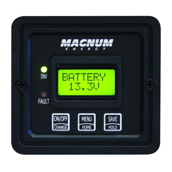
Front Panel The ME-MR front panel contains two LEDs and a LCD display for viewing system status, and three buttons to control system operation. 5.1.1... -
Page 29: Operating The Inverter/Charger
(see Section 6.2), or if all power to the remote or inverter is removed. Info: The ME-MR remote is only used to control an inverter. In order to control or display a Magnum Energy accessory, you need to use a ME-RC50 or ME-ARC50 remote control. -
Page 30: System Status Messages
5.0 Operation System Status Messages The remote control uses the bottom line of the LCD display to show the inverter/charger’s operation by displaying a status message. This section will review the inverter/charger’s operating modes and the available status messages under each mode. Use these messages along with the status LEDs to determine the inverter/charger’s current operating status, and to assist in troubleshooting the system if a fault occurs. -
Page 31: Charger Mode Messages
5.0 Operation Off appears on the LCD. All LEDs are off. STATUS Figu r e 5 - 4 , Off • Off – This message tells you that there is no AC available on the inverter’s AC output. The inverter function is off. Search appears on the LCD. - Page 32 5.0 Operation Bulk appears on the LCD. The FAULT (red) LED is off, and the INV (green) LED could be on or off. STATUS Bulk Figu r e 5 - 7 , Bu lk Ch a r gin g • Bulk Charging –...
- Page 33 5.0 Operation EQing appears on the LCD. The FAULT (red) LED is off, and the INV (green) LED could be on or off. STATUS EQing Figu r e 5 - 1 0 , Equ a lizin g • Equalizing – The battery charger is delivering the equalize voltage to the batteries.
- Page 34 5.0 Operation Full Chg appears on the LCD. The FAULT (red) LED is off, and the INV (green) LED could be on or off. STATUS Full Chg Figu r e 5 - 1 2 , Fu ll Ch a r ge •...
- Page 35 5.0 Operation LS VDC appears on the LCD. The FAULT (red) LED is off, and the INV (green) LED is on. STATUS LS VDC Figu r e 5 - 1 4 , Loa d Su ppor t VD C • Load Support VDC –...
-
Page 36: Fault Mode Messages
5.0 Operation 5.3.3 Fault Mode Messages When an abnormal condition is detected, the FAULT LED comes on and a fault status is displayed. View the LCD display and use the information in this section to identify and correct the issue. Info: Many faults automatically restart once cleared. - Page 37 5.0 Operation Brk Trip appears on the LCD and the FAULT (red) LED is on. The INV (green) LED is off. FAULT ! Brk Trip Figu r e 5 - 1 8 , Br e a k e r Tr ippe d Fa u lt •...
- Page 38 5.0 Operation FetOvrld appears on the LCD and the FAULT (red) LED is on. The INV (green) LED is off. FAULT ! FetOvrld Figu r e 5 - 2 0 , FET Ove r loa d Fa u lt • FET Overload Fault –...
- Page 39 5.0 Operation HiBaTemp appears on the LCD and the FAULT (red) LED is on. The INV (green) LED is off. FAULT ! HiBaTemp Figu r e 5 - 2 2 , H igh Ba t t e r y Te m p Fa u lt •...
-
Page 40: Figure 5-25, No Communication
5.0 Operation Low Batt appears on the LCD and the FAULT (red) LED is on. The INV (green) LED is off. FAULT ! Low Batt Figu r e 5 - 2 4 , Low Ba t t e r y Fa u lt •... - Page 41 5.0 Operation OvrCurnt appears on the LCD and the FAULT (red) LED is on. The INV (green) LED is off. FAULT ! OvrCurnt Figu r e 5 - 2 6 , Ove r cu r r e n t Fa u lt •...
- Page 42 5.0 Operation StkRelay appears on the LCD and the FAULT (red) LED is on. The INV (green) LED is off. FAULT ! StkRelay Figu r e 5 - 2 8 , St u ck Re la y Fa u lt •...
- Page 43 5.0 Operation 5.3.3.2 Stacking Fault Messages A fault condition may occur when multiple inverters are connected together (i.e., stacked)—that is not possible on a single inverter installation. Stak CLK appears on the LCD and the FAULT (red) LED is on. The INV (green) LED is off.
-
Page 44: Internal Fault Messages
5.0 Operation 5.3.3.3 Internal Fault Messages The inverter continually monitors several internal components. If a condition inside the inverter occurs that does not allow proper operation, the inverter shuts down to protect itself. An inverter reset is required to clear these faults. -
Page 45: Led Indicator Guide
5.0 Operation IntRelay appears on the LCD and the FAULT (red) LED is on. The INV (green) LED is off. FAULT ! IntRelay Figu r e 5 - 3 7 , I n t e r n a l Re la y Fa u lt •... -
Page 46: Troubleshooting
6.0 Troubleshooting Troubleshooting If the remote is not functioning correctly, use the following table to help fi nd a solution. Table 6-1, Remote Troubleshooting Symptom Possible Cause Solution Display shows Static electricity Refresh display: Press and unrecognizable may have been hold the MENU/HOME button for letters or discharged into the... -
Page 47: Troubleshooting Tips
Remote displays “Float” not “Bulk” when the AC is fi rst plugged in: Check DC volts on the ME-MR display, if the battery is over 13.0 VDC (26.0 VDC for 24-volt models or 52.0 VDC for 48-volt models) then the battery was already charged and the charger automatically goes to Float Charging to keep from overcharging the batteries. -
Page 48: Performing An Inverter Reset
Info: The Power ON/OFF pushbutton is a small momentary type switch which operates by lightly pressing and releasing. Info: All adjustable inverter/charger settings in the ME-MR are saved in non-volatile memory and are preserved until changed— even if an inverter reset is performed, or if all power to the remote or inverter is removed. -
Page 49: Warranty Information
7.0 Warranty Information Warranty Information Warranty Statement Sensata Technologies (hereafter “Sensata”) warrants the ME-MR remote to be free from defects in material and workmanship that result in product failure during normal usage, according to the following terms and conditions: The limited warranty for this product extends for a maximum of 12 months from the product’s original date of purchase. - Page 50 Magnum Energy Products Manufact ured by: Sensata Technologies www.SensataPower.com ME-MR Owner’s Manual (PN: 64-0031 Rev F)
Need help?
Do you have a question about the ME-MR and is the answer not in the manual?
Questions and answers