Advertisement
Quick Links
STOCK CODE #
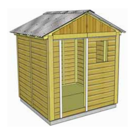
GAR88-FJ-METAL
Thank you for purchasing
an 8x8 Gardener's Shed.
Please take the time to
identify all the parts prior
to assembly.
Safety Points and Other Considerations
Our products are built for use based on
proper installation and normal residential use,
on level ground. Please follow the instruction
manual when building your shed and retain
the manual for future maintenance purposes.
Some of the safety and usage measures you may wish to consider include:
-snow load ratings vary by geographical location. If heavy or wet snowfall occurs, it is advisable to sweep the
snow off the roof(s).
-if the product is elevated, any structural and building code requirements are solely the customer's
responsibility, and should be abided by.
-in high or gusty wind conditions it is advisable to keep the structure securely grounded.
-have a regular maintenance plan to ensure screws, doors, windows and parts are tight.
Customer agrees to hold Outdoor Living Today Partnership and any Authorized Dealers free
of any liability for improper installation, maintenance and repair.
In the event of a missing or broken piece, simply call the Outdoor Living Today Customer
Support Line @ 1-888-658-1658 within 30 days of the delivery of your purchase. It is our
commitment to you to courier replacement parts, free of charge, within 10 business days of
this notification. Replacement parts will not be provided free of charge after the 30 day grace
period.
Toll Free 1-888-658-1658
8x8 Gardener's Shed -
Metal Roof - Finger Jointed Siding
- Assembly Manual
www.outdoorlivingtoday.com
Page 1
Version 1.3
July 22, 2021
sales@outdoorlivingtoday.com
Advertisement

Related Manuals for OLT Gardener's Shed GAR88-FJ-METAL


Summary of Contents for OLT Gardener's Shed GAR88-FJ-METAL
- Page 1 8x8 Gardener’s Shed - Metal Roof - Finger Jointed Siding - Assembly Manual Version 1.3 July 22, 2021 STOCK CODE # GAR88-FJ-METAL Thank you for purchasing an 8x8 Gardener’s Shed. Please take the time to identify all the parts prior to assembly. Safety Points and Other Considerations Our products are built for use based on proper installation and normal residential use,...
- Page 2 What to do before my Shed arrives? • Become familiar with this assembly manual and determine if you can complete the project yourself or will require a professional contractor. • One helper is recommended to assist in constructing your shed. It generally takes two people over two days to assemble a shed.
- Page 3 Foundation Types for 8x8 Garden Shed 96” 96” 91” 91” Shed Front Shed Front Shed Front Concrete Foundation Floor Frame Completed Foundation Concrete Slab Foundation: - Slab must be at least the same size as assembled floor frame (91” x 96”) or larger. - 6”...
- Page 4 Thank you for purchasing our 8x8 Gardener’s Shed. Parts List - Page 2 Please take the time to identify all the parts prior to assembly. Steps 1. Floor Section Floors 2 - 45 1/2” x 75” - Floor Joist Frames - Large 1-11 2 - 45 1/2”...
- Page 5 8x8 GARDENER - METAL - HARDWARE SHEET Hardware Kit (Provided) x 48 1/4”x 2” Metal Roof Screw 2 1/2” x 228 x 308 1 1/2” 2” x 120 Finishing x 22 2” Square Drive Bit Black Headed x 267 1 1/4” 1/4”...
- Page 6 Regular Maintenance & Tips to prolong the life of your shed. Before/During Assembly: 1.) Paint each face and edge of your plywood floor with a latex exterior paint. 2.) Caulk wall seams if gaps appear. 3.) Caulk around window framing. 4.) Caulk perimeter between floor plywood and bottom wall plate.
- Page 7 A. Floor Section Exploded view of all parts necessary to complete Floor Section. Identify all parts prior to starting. Note: Floor Footprint is 96” wide x 91” deep. Plywood Floor Plywood Floor Small (2) Large (2) Floor Joist Frames Small (2) Floor Runners (10) Floor Joist Concrete Pad...
- Page 8 You can find the Square Drive Bit for the screws in with the Hardware Kit Bag. When correctly positioned, attach each Joist with 4 - 2 1/2” screws (2 per end). Lay out Floor Joist Frames as illustrated at left. There are 2 larger and 2 smaller Frame Sections.
- Page 9 Parts (Steps 7 - 9) Hardware (Steps 7 - 9) Attach Floor Runners to completed floor frame. Floor Runner Short S1 - 2 1/2” Screws There are 2 Floor Runners per 91” side and 5 complet- (1 1/2” x 3 1/2” x 31”) x 5 x 30 total ed runners in total.
- Page 10 11 . With Plywood positioned correctly on Hint: Use a chalk floor framing, attach line to mark location with 1 1/4” screws. Use of floor joists to screws every 16”. determine screw placement. B. Wall Section Exploded view of all parts necessary to complete the Wall Section.
- Page 11 Parts (Steps 13 - 21) Lay out all the wall panels and become familiar with their Solid Wall Panels location. On a Standard Kit, there is 1 Window Wall Panel, 6 Solid (45 1/2” x 75”) x 5 Wall Panels and 1 Narrow Wall Panel. Make sure to position pan- Window Wall Panel els right side side up so water is directed away from and not into (45 1/2”...
- Page 12 Do Not Attach Walls To Floor Until Step 25. Optional: Caulking seams will help prevent moisture from entering at seam. Caulking not included in kit. This will help the longevity of your shed. Position a 2nd Solid Wall into place on plywood floor. Butt both vertical wall studs of side and rear walls together and attach with 3 - 2 1/2”...
- Page 13 Make sure top Wall framing is aligned Place Window Wall Panel in front. together as illustrated and attach as per Step 17. Parts (Steps 22) Position and attach Narrow Wall Panel to left side Narrow Wall Panel wall stud with 3 - 2 1/2” screws as per Step 16. Note: (12”...
- Page 14 Header has notch in edge that is positioned to the top and facing outside. Parts (Steps 24) Hardware (Steps 24) Position and attach Door Header to Door Jamb Door Header S1 - 2 1/2” Screws and Narrow Wall Panel top framing. Header should sit (2”...
- Page 15 Top Plates should be flush with inside of wall framing. Angle cut on ends. Hardware (Steps 26,28) Position Front Top Plates on top of wall studs so they are S3 - 2” Screws flush on the inside with 2x3 wall framing. There are 3 pieces of x 18 total Front Top Plates (2 angle cut on one end and one straight cut on Parts (Steps 26,28)
- Page 16 Male & Female Notch Ends Notched at top Flashing Flashing Parts (Steps 29-32) Hardware (Steps 29-32) Locate Gable 1/2 Walls for both sides of shed. Gable Half Walls S1 - 2 1/2” Screws Align framing and gable lapp siding together. Screw Triangular shaped x 4 x 6 total center gable wall framing of each piece together...
- Page 17 straight edge Flashing overhangs wall siding. The gable should be centered sideways (left to right) on the top plate. Hint: use a straight edge to check the angle of the gable framing and top plate. Both angles should line up. Adjust gable accordingly.
- Page 18 C. Rafter and Roof Section Exploded view of all parts necessary to complete the Roof Section. Identify all parts prior to starting. Metal Ridge Caps (2) Metal Roof Panels (6) Foam Enclosures (Several) Batten Spacers (12) Roof Battens Roof Battens Short 25 1/2”...
- Page 19 Locate 6 Rafters, 2 Soffits and 56 1/2” Rafters Ridge Board completed Ridge Board from Step 33. Lay out as illustrated on a flat level sur- face. Parts (Step 34 - 42) Rafters (1 1/2” x 3 1/2” x 56 1/2”)x 12 Soffits (1/2”...
- Page 20 Soffit Gable Notch Slide Rafter Section up on gable Flip Rafter Section over so Soffit is facing down. framing until bottom of Ridge Board slips Starting with the left side, lift completed rafter section into gable notch. up and place on gable framing. Rafter should rest on gable framing When...
- Page 21 91” 91” 91” Take the inside - to inside measurment between Top Wall Plates and Bottom Wall Plates at the front middle and rear of your shed. These measurements should each be approximatley 91”, but more importantly, if they are not within 1/4” of each other than your walls are not square. Ensure walls are square before attaching Ridge Boards together in Step 42.
- Page 22 Hardware (Step 43) With both Ridge Boards connected, completely secure Gable framing to S2 - 1 1/4” Screws walls and rafters. Use 4 - 2” screws per Rafter. Use an additional 6 - 2” x 28 total screws to secure Gable to wall. Note: you may have to remove the 2 tem- porary screws in Gable from Step 32 and reposition Gable for best fit prior to completing gable attachment.
- Page 23 Parts (Step 46) Hardware (Step 46) Locate 2 Roof Battens and place one of each Roof Battens S2 - 1 1/4” Screws on roof rafters. Place at top of Rafter section where (3/4” x 3 1/2” x 48 1/4”) x 2 x 6 total Rafter and Ridge Boards meet.
- Page 24 Parts (Step 49) Hardware (Step 49) Locate 2 more Roof Battens. Place both Roof Battens S2 - 1 1/4” Screws Battens flush against Batten Spacers installed in (3/4” x 3 1/2” x 48 1/4”) x 2 x 10 total Step 48. Battens will overhang outside Rafter by 2 Batten Spacers 3/4”...
- Page 25 Parts (Step 46) To complete opposite side of roof repeat Steps 46 - 50. Roof Battens (3/4” x 3 1/2” x 48 1/4”) x 8 Hardware (Step 51) Batten Spacers S2 - 1 1/4” Screws (3/4” x 1 1/2” x 14”) x 6 x 36 total Important: Do not fasten down Metal Roof Panels with Hangers still in place.
- Page 26 4”of overhang set by metal roof hangars Overhang the Metal Roof Panels past the Battens on sides approximatley 1”. Adjust panels side- to side tto achieve desired width. Overall width past the Battens can vary from 1” - 3” depending on your preference.
- Page 27 Important: Remove Metal Roof Hangers Parts (Step 56) Before fully fastening Metal Roof Panels down, remove the Metal Foam Enclosures Roof Hangers and insert Foam Enclosures between Metal Roof Panels (Several Pcs) and Battens at the bottom of the roof. Enclosures will prevent moisture and unwanted bugs, etc from entering your shed through here.
- Page 28 Parts (Step 59) Locate remaining Foam Enclosures. Place Foam Enclosures at the Foam Enclosures top of the roof panels. Foam Enclosures prevent moisture from coming in (Several Pcs) through the top of your shed. Parts (Step 60) Place 2 Metal Ridge Caps onto apex of roof. Evenly space from Metal Ridge Caps front to back of your shed Caps will overlap eachother.
-
Page 29: Table Of Contents
D. Miscellaneous Section Not Shown: missing from Exploded view of all parts necessary to complete the exploded drawing: Interior Miscellaneous Section. Identify all parts prior to starting. Door Stops, Top Wall Trim. Facia Nailing Pentagon Cleat (4) Facia Piece (2) Facia / Trim Detail Plate Filler... -
Page 30: Filler Trim
Expert Advice: When installing trim, sort pieces according to color and pieces that are most pleas- ing to the eye. Start with least visible side and use the least desirable pieces first. Install trim to most visible sides as your skill installing trim improves. Parts (Steps 62) Hardware (Steps 62) Attach Filler Trims to each corner side wall. -
Page 31: Corner Trims
Corner Trim Wide Corner Trim Parts (Steps 64 - 65) To trim out corners, start with Narrow Trim, align tight Corner Trim underneath Soffit and Rafter. Align Wide Corner Trim (1/2” x 3 1/2” x 79”) x 4 with bottom of Corner Trim. Do a dry run in each corner Wide Corner Trim before attaching to confirm positioning. -
Page 32: Drip Edge
Horizontal Gable Trims Drip Edge over Drip Edge Parts (Steps 67) Hardware (Steps 67) Position Drip Edges so they are ovelapping Horizontal Gable Trim N1 - 1 1/2” Finishing eachother above dooryway flush with Wide Corner Trims. (1/2” x 4 1/2” x 43 3/8”) x 2 Nails With Drip Edges in place, place Front Horizontal Gable Drip Edges x2... - Page 33 Parts (Steps 69-70) Attach Rear Wall Narrow Trims where wall panels come Rear/Front Wall Narrow Trim together and leave a seam. Position trim equally on wall seam (1/2” x 2 1/2” x 77 1/2”) x 3 and tight underneath Horizontal Gable Trim. Use 8 - 1 1/2” Hardware (Steps 69-70) Finishing Nails to secure.
- Page 34 Position Rear Facia (angle cut ends) and Side Facia (square cut ends) in corner. Line up so angle cut Facia caps square cut Facia. Attach angled Facia to Nailing Strip with 8 - 1 1/2” Finishing Nails per piece. Gap Where Facia boards come together at peak will be covered by a detail plate in Step 72.
- Page 35 Attach Door Hinges to Door Panel as shown above. Position Hinges equally on Door Trim as shown above and attach with 1 -3/4” Black Screw and 2 - 2” Black Screws per hinge. Parts (Steps 75) Door (31 1/2” x 72”) x 1 Hardware (Steps 75) SB1 - 3/4”...
- Page 36 Hardware (Steps 77) Attach Black Drop Latch and Black Handle as illustrated above. Y3 - Black Handle Attach the Black Latch with 4 - 2” Black Screws & 1 - 3/4” Black x 1 total Screw. Not how femal part of Barrel Bolt is positioned higher than male. Y5 - Black Latch Do a dry run first to position latch correctly.
- Page 37 Window frame. Caulk gap. Screw insert into bottom (thick) part of siding. Parts (Step 79) To reduce possible water from penetrating Window Insert x 1 into the window cavity, caulk gap on both sides of window opening prior to installing Window Hardware (Step 79) Insert.
- Page 38 Trim dado sits in flange. Position Window Trim around window doing a dry run first and attach with 4 - 1 1/2” Finishing Nails per piece. Window trim has a small dado on reverse face. Outside flange of window will roughly sit in the dado to give a better fit. Parts (Step 81) Hardware (Steps 81) Window Trim Package x 1...
- Page 39 Outdoor Living Today Flower Box Assembly Instructions Exploded Side Trims (D) View Front Trim (C) End Caps (B) 1 1/4” Parts Lists: Nails (G) A - Base, Rear & Front Box Frames (3pcs) 3/4” x 5 1/2” x 23” B - End Cap Frames (2pcs) 3/4”...
- Page 40 Congratulations on building your 8x8 Gardener’s Shed! Note: Our Sheds are shipped as unfinished products. If exposed to the elements, the western red cedar lumber will weather to a silvery-gray color. If you prefer to keep the cedar lumber looking closer to the original color, we suggest that you treat the wood with a good oil base wood stain.
Need help?
Do you have a question about the Gardener's Shed GAR88-FJ-METAL and is the answer not in the manual?
Questions and answers