Table of Contents
Advertisement
Quick Links
Version #1.0
November 20, 2023
Stock Code:
GC42-FJ-CEDAR
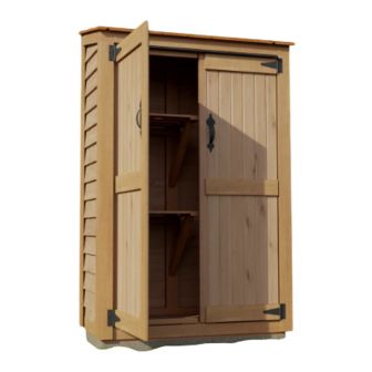
Thank you for purchasing a
4x2 Garden Chalet.
Please take the time to
identify all the parts prior to
assembly.
Important Information:
- It is the sole responsibility of the customer to check with your local municipal or county by-laws before
ordering this product to confirm it complies with building codes in your area.
- If the product is elevated, any structural and building code requirements are solely the customer's
responsibility, and should be abided by.
- Snow load ratings vary by geographical location. If heavy or wet snowfall occurs, it is advisable to sweep
snow off roof frequently.
- In areas with high or gusty wind conditions, it is advisable to install the structure securely to the ground.
- Have a regular maintenance plan to ensure screws, doors, windows and parts are tightly affixed.
- All structures purchased from Outdoor Living Today are covered for a period of one year for defects in
manufacturing and workmanship. Costs incurred for customer installations are not included.
- Failure to use supplied parts included in this kit could result in poor product performance and may void your
warranty. Please contact Outdoor Living Today's Customer Toll Free Line if you plan to deviate from our
written instructions.
Customer agrees to hold Outdoor Living Today and any Authorized Dealers free of any liability for improper
installation, maintenance and repair.
In the event of a missing or broken piece, simply call the Outdoor Living Today Customer Support Line
@ 1-888-658-1658 within 30 days of the delivery of your purchase. It is our commitment to you to courier
replacement parts, free of charge, within 10 business days of this notification. Replacement parts will not be
provided free of charge after the 30 day grace period.
Outdoor Living Today
4x2 GARDEN CHALET
WITH CEDAR ROOF
ASSEMBLY MANUAL
www.outdoorlivingtoday.com
Page 1
sales@outdoorlivingtoday.com
Advertisement
Table of Contents

Subscribe to Our Youtube Channel
Related Manuals for OLT GC42-FJ-CEDAR


Summary of Contents for OLT GC42-FJ-CEDAR
- Page 1 4x2 GARDEN CHALET WITH CEDAR ROOF ASSEMBLY MANUAL Version #1.0 November 20, 2023 Stock Code: GC42-FJ-CEDAR Thank you for purchasing a 4x2 Garden Chalet. Please take the time to identify all the parts prior to assembly. Important Information: - It is the sole responsibility of the customer to check with your local municipal or county by-laws before ordering this product to confirm it complies with building codes in your area.
- Page 2 What to do before my Shed arrives? • Become familiar with this assembly manual and determine if you can complete the project yourself or will require a professional contractor. • One helper is recommended to assist in constructing your chalet. It generally takes two people less than a day to assemble a chalet.
- Page 3 Foundation Types for 4x2 Garden Shed 42” 19 1/2” Concrete Foundation Concrete Slab Foundation: - Slab must be at least the same size as assembled floor frame (19 1/2” x 42”) or larger. - 2” Deep foundation. - 0.4 Cubic Yards of concrete required. - A concrete slab will have the longest durability out of your foundation options.
-
Page 4: Wall Section
Thank you for purchasing our 4x2 Garden Chalet. Please take the time to identify all the parts prior to assembly. Parts List Steps D. - Trim / Misc. Section Cont. Steps A. - Floor Section Outer Wall Trim and Facia 28 - 34 Floor 1 - Metal Drip Edge - 38”... - Page 5 4x2 GARDEN CHALET - CEDAR ROOF Hardware Kit (Provided) 3/4” 3” 3 pcs Black Headed Screw 2 1/2” 54 pcs 150 pcs 1 1/2” Finishing 2” 26 pcs 1 1/2” 4 pcs Black Headed Bolt with Silver Nut and Washer 14 pcs 2”...
- Page 6 Regular Maintenance & Tips to prolong the life of your shed. Before/During Assembly: 1.) Paint each face and edge of your plywood floor with a latex exterior paint. 2.) Caulk wall seams if gaps appear. 3.) Caulk around window framing. 4.) Caulk perimeter between floor plywood and bottom wall plate.
- Page 7 For assembly instructions of your Garden Chalet with a low front, start at page 8. For assembly instructions of your Garden Chalet with a high front, start at page 31. Outdoor Living Today www.outdoorlivingtoday.com sales@outdoorlivingtoday.com Page 7...
- Page 8 A. Floor Section Exploded view of all parts necessary to complete the Wall Section. Identify all parts prior to starting. Floor Section Parts Locate Floor Section and flip over and lay on a level Floor Section foundation only. Patio Stones or a Concrete Slab both make (19 1/2”...
-
Page 9: Table Of Contents
B. Wall Section Exploded view of all parts necessary to complete the Wall Section. Identify all parts prior to starting. Low End Top Plate Door Header Wall Extender Rear Wall Panels (2) Shelf Support Cleats (2) Side Wall Panels - Shelf Supports - Angled Angled (2) Storage Shelves (2) - Page 10 Wall Panels (Rear) Wall Panel (Side) Wall Panel (Side) Floor With Wall Plates properly attached, orientate completed Walls around the Floor. Be sure to leave room to work. Left Side Wall Wall frame flush with Before completely outside of Floor at attaching walls to floor, the rear.
- Page 11 Left Side Wall Rear Wall With your helper holding the Side Wall Panel, position a Rear Wall Panel in rear corner. Important: Align Wall Framing Flush with Floor Framing. Wall frame flush with outside Floor. Wall siding will overhang Floor. 2 1/2”...
- Page 12 2 1/2” Brown Screws Position second Rear Wall Panel on Floor as per Step 6. Attach Wall frames together at top, middle and bottom with 3 - 2 1/2” Brown Screws. A wood clamp will be helpful in holding pieces together while fastening.
- Page 13 2 1/2” Brown Screws Locate both Door Jambs. Position each Door Jamb tight to Side Wall framing and flush with the floor. Screw each Door Jamb into wall framing with 3 - 2 1/2” Brown Screws per piece. Parts Hardware Door Jambs 2 1/2”...
- Page 14 36” With Door Header installed, confirm Door width at both the top and bottom of the doorway. Doorway opening should be 36” wide. If required, loosen screws in Side Walls, adjust Door width 36” and re-secure. There can be a 1/8” tolerance in the width but both top and bottom should match.
- Page 15 36” Hardware With Walls secured, confirm again that the doorway opening is 36”. 2 1/2” Brown Screws Check interior corner to corner measurements are 42 3/8” across diagonally. x 12 total With doorway measurement confirmed, begin to fasten Wall Panels down to Floor with 2 1/2”...
-
Page 16: Shelf Support
Locate Low End Top Plate and position on top of Door Header. Secure Low End Top Plate to Door Header with 4 - 2 1/2” Brown Screws. Parts Hardware Low End Top Plate 2 1/2” Brown Screws (1 1/2” x 1 1/2” x 39”) x 4 total Locate Shelf Support Cleats. -
Page 17: Shelf Supports - Angled
Place two Shelf Supports underneath Shelf. Drill 2 - 2” Brown Screws through Shelf Support into underside of Shelf at the top and through Shelf Support into Rear Wall Framing at the bottom. Parts Hardware Shelf Supports - Angled 2” Brown Screws (1 1/2’... - Page 18 C. Roof Section Exploded view of all parts necessary to complete the Roof Section. Identify all parts prior to starting. Cedar Shingle Roof Panel Plywood roofing flush with Plywood roofing flush with Side Wall framing at the side Side Wall framing. and at rear.
- Page 19 2” Brown Screws 2” Brown Screws 90° Metal Bracket 90° Metal Bracket Check the Wall seams for visible gaps prior to attaching Filler Trim and apply caulk where needed. Caulking gaps will help prevent moisture from entering and will help the longevity of your shed.
- Page 20 D. Miscellaneous Section Exploded view of all parts necessary to complete the Skirting, Trim, Fascia and Miscellaneous Pieces. Identify all parts prior to starting. Roof Ridge Cap Side Fascia Trims (2) Horizontal Filler Trims (2) Low Wide Trims (2) Left and Right Doors Low Side Trims (2) with Hardware Door Flange...
- Page 21 Locate Front/Rear Skirting. Skirting will hide Floor framing and gaps will be covered by Wide Trim pieces later. Attach Front/Rear Skirting pieces with 6 - 1 1/2” Finishing Nails per piece. Locate Side Skirting and attach with 4 - 1 1/2” Finishing Nails per piece. Hardware 1 1/2”...
- Page 22 Position and attach 2 more Filler Trims and High Side Filler Trims at the rear as per Step 26. Outdoor Living Today www.outdoorlivingtoday.com sales@outdoorlivingtoday.com Page 22...
- Page 23 Expert Advice: Do a dry run with Front/Rear Horizontal and Side Fascia Trims before attaching. Confirm the rough face is configured correctly and small trim gaps are satisfactory before attaching. Locate Metal Drip Edge and Front Horizontal Trim. Position Metal Drip Edge onto Horizontal Filler Trims.
- Page 24 Expert Advice: Do a dry run with Front and Rear Corner trims before attaching. Confirm the rough face is configured correctly and small trim gaps are satisfactory before attaching. Locate Low Wide Trims and Low Side Trims. Position first Low Wide and Low Side Trims underneath Front Horizontal Trim and Side Fascia.
- Page 25 Parts (Step 33 - 34) Hardware (Step 33 - 34) High Wide Trim 1 1/2” Finishing Nails (1/2” x 3” x 67 1/4”) x 2 x 30 total High Side Trim (Angle Cut) (1/2” x 2 1/2” x 67 1/4”) x 2 High Middle Trim (1/2”...
- Page 26 Door Flange Drill Pilot Holes to prevent splitting. 1 1/2” Bolt Left Door Right Door Align barrel of Hinge on center of door trim as shown above Outdoor Living Today www.outdoorlivingtoday.com sales@outdoorlivingtoday.com Page 26...
- Page 27 1/8” 1 - 2” Screw per Hinge Initially. Starting with Right Door first, lift and position Door in opening. Leave a 1/8” gap on right side and 1/8” gap on the bottom. Use a Cedar Shingle Shim to shim the Door at bottom to help position door evenly.
- Page 28 2 more - 2” Black Headed Screws per Hinge With both Doors partially attached, check to see Doors open and close correctly. Make any necessary adjustments and when satisfied, completely secure Hinges to Low Wide Trims with two more 2” Black Headed Screws per Hinge. Drill pilot holes to prevent wood from splitting. Attach Door Handles to Doors with 4 - 3/4”...
- Page 29 Important: Drill shallow Pilot Holes to prevent splitting. 3/4” Black Screws Drop Latch Receiver 3/4” Black Screws 3/4” Black Screw Attach Black Drop Latch as illustrated above with 6 - 3/4” Black Headed Screws. Note: Black Drop Latch receiver is positioned higher than male. Do a dry run first to position Black Drop Latch correctly.
- Page 30 Using a Step Ladder, place Roof Ridge Cap on front row of Roof Shingles. Attach Ridge Cap with 4 - 1 1/2” Finishing Nails. Parts Hardware Roof Ridge Cap 1 1/2” Finishing Nails (1/2” x 3 1/2” x 46”) x 4 total Outdoor Living Today www.outdoorlivingtoday.com sales@outdoorlivingtoday.com...
- Page 31 A. Floor Section Exploded view of all parts necessary to complete the Wall Section. Identify all parts prior to starting. Floor Section Parts Locate Floor Section and flip over and lay on a level Floor Section foundation only. Patio Stones or a Concrete Slab both make (19 1/2”...
-
Page 32: For Each Wall Panel, Carefully Lay Panel Face Down. Position And Attach A Bottom Wall Plate To
B. Wall Section Exploded view of all parts necessary to complete the Wall Section. Identify all parts prior to starting. Wall Extender Low End Top Plate Rear Wall Panels (2) Door Header Shelf Support Cleats (2) Side Wall Panels - Shelf Supports - Angled Angled (2) Storage Shelves (2) - Page 33 Wall Panels (Rear) Wall Panel (Side) Wall Panel (Side) Floor With Wall Plates properly attached, orientate completed Walls around the Floor. Be sure to leave room to work. Left Side Wall Wall frame flush with Before completely outside of Floor at attaching walls to floor, the rear.
- Page 34 Left Side Wall Rear Wall With your helper holding the Side Wall Panel, position a Rear Wall Panel in rear corner. Important: Align Wall Framing Flush with Floor Framing. Wall frame flush with outside Floor. Wall siding will overhang Floor. 2 1/2”...
- Page 35 2 1/2” Brown Screws Position second Rear Wall Panel on Floor as per Step 6. Attach Wall frames together at top, middle and bottom with 3 - 2 1/2” Brown Screws. A wood clamp will be helpful in holding pieces together while fastening.
- Page 36 2 1/2” Brown Screws Locate both Door Jambs. Position each Door Jamb tight to Side Wall framing and flush with the floor. Screw each Door Jamb into wall framing with 3 - 2 1/2” Brown Screws per piece. Parts Hardware Door Jambs 2 1/2”...
- Page 37 36” With Door Header installed, confirm Door width at both the top and bottom of the doorway. Doorway opening should be 36” wide. If required, loosen screws in Side Walls, adjust Door width 36” and re-secure. There can be a 1/8” tolerance in the width but both top and bottom should match.
- Page 38 36” Hardware With Walls secured, confirm again that the doorway opening is 36”. 2 1/2” Brown Screws Check interior corner to corner measurements are 42 3/8” across diagonally. x 12 total With doorway measurement confirmed, begin to fasten Wall Panels down to Floor with 2 1/2”...
- Page 39 Locate Low End Top Plate and position on top of Rear Walls. Secure Low End Top Plate to Rear Walls with 4 - 2 1/2” Brown Screws. Parts Hardware Low End Top Plate 2 1/2” Brown Screws (1 1/2” x 1 1/2” x 39”) x 4 total Locate Shelf Support Cleats.
- Page 40 Place two Shelf Supports underneath Shelf. Drill 2 - 2” Brown Screws through Shelf Support into underside of Shelf at the top and through Shelf Support into Rear Wall Framing at the bottom. Parts Hardware Shelf Supports - Angled 2” Brown Screws (1 1/2’...
- Page 41 C. Roof Section Exploded view of all parts necessary to complete the Roof Section. Identify all parts prior to starting. Cedar Shingle Roof Panel Plywood roofing flush with Plywood roofing flush with Side Wall framing at the side Side Wall framing. and at front.
- Page 42 2” Brown Screws 2” Brown Screws 90° Metal Bracket 90° Metal Bracket Check the Wall seams for visible gaps prior to attaching Filler Trim and apply caulk where needed. Caulking gaps will help prevent moisture from entering and will help the longevity of your shed.
- Page 43 D. Miscellaneous Section Exploded view of all parts necessary to complete the Skirting, Trim, Fascia and Miscellaneous Pieces. Identify all parts prior to starting. Roof Ridge Cap Side Fascia Trims (2) Horizontal Filler Trim Above Door Trim High Wide Trims (2) High Side Trims (2) Left and Right Doors with Hardware...
- Page 44 Locate Front/Rear Skirting. Skirting will hide Floor framing and gaps will be covered by Wide Trim pieces later. Attach Front/Rear Skirting pieces with 6 - 1 1/2” Finishing Nails per piece. Locate Side Skirting and attach with 4 - 1 1/2” Finishing Nails per piece. Hardware 1 1/2”...
- Page 45 Position and attach 2 more Filler Trims and High Side Filler Trims at the front as per Step 25. Expert Advice: Do a dry run with Front/Rear Horizontal and Side Fascia Trims before attaching. Confirm the rough face is configured correctly and small trim gaps are satisfactory before attaching. Locate Front Horizontal Trim.
- Page 46 Parts Hardware Side Fascia Trim (Angle Cut Both Ends) 1 1/2” Finishing Nails (1/2” x 2 1/2” x 22 1/8”) x 4 total Hardware 1 1/2” Finishing Nails x 10 total Locate Metal Drip Edge and Above Door Trim. Position Metal Drip Edge onto Wall Extender and between High Side Filler Trim.
- Page 47 Expert Advice: Do a dry run with Front and Rear Corner trims before attaching. Confirm the rough face is configured correctly and small trim gaps are satisfactory before attaching. Locate High Wide Trims and High Side Trims. Position first High Wide and High Side Trims underneath Front Horizontal Trim and Side Fascia.
- Page 48 Parts (Step 33 - 34) Hardware (Step 33 - 34) Low Wide Trims 1 1/2” Finishing Nails (1/2” x 3” x 62 7/8”) x 2 x 30 total Low Side Trims (Angle Cut) (1/2” x 2 1/2” x 63 3 /8”) x 2 Low Middle Trim (1/2”...
- Page 49 Door Flange Drill Pilot Holes to prevent splitting. 1 1/2” Bolt Left Door Right Door Align barrel of Hinge on center of door trim as shown above Outdoor Living Today www.outdoorlivingtoday.com sales@outdoorlivingtoday.com Page 49...
- Page 50 1/8” 1 - 2” Screw per Hinge Initially. Starting with Right Door first, lift and position Door in opening. Leave a 1/8” gap on right side and 1/8” gap on the bottom. Use a Cedar Shingle Shim to shim the Door at bottom to help position door evenly.
- Page 51 2 more - 2” Black Headed Screws per Hinge With both Doors partially attached, check to see Doors open and close correctly. Make any necessary adjustments and when satisfied, completely secure Hinges to High Wide Trim with two more 2” Black Headed Screws per Hinge. Drill pilot holes to prevent wood from splitting. Attach Door Handles to Doors with 4 - 3/4”...
- Page 52 Important: Drill shallow Pilot Holes to prevent splitting. 3/4” Black Screws Drop Latch Receiver 3/4” Black Screws 3/4” Black Screw Attach Black Drop Latch as illustrated above with 6 - 3/4” Black Headed Screws. Note: Black Drop Latch receiver is positioned higher than male. Do a dry run first to position Black Drop Latch correctly.
- Page 53 Using a Step Ladder, place Roof Ridge Cap on front row of Roof Shingles. Attach Ridge Cap with 4 - 1 1/2” Finishing Nails. Parts Hardware Roof Ridge Cap 1 1/2” Finishing Nails (1/2” x 3 1/2” x 46”) x 4 total Outdoor Living Today www.outdoorlivingtoday.com sales@outdoorlivingtoday.com...
- Page 54 Note: Our Sheds are shipped as an unfinished product. If exposed to the elements, the lumber will weather to a silvery-gray color. If you prefer to keep the lumber looking closer to the original color, we suggest that you treat the wood with a good oil base wood stain.
Need help?
Do you have a question about the GC42-FJ-CEDAR and is the answer not in the manual?
Questions and answers