Table of Contents
Advertisement
Quick Links
Advertisement
Table of Contents

Related Manuals for Tech Controllers EU-L-7E


Summary of Contents for Tech Controllers EU-L-7E
- Page 1 Users manual EU-L-7e...
-
Page 2: Table Of Contents
TABLE OF CONTENTS Safety..................................... 3 Device description ................................. 4 III. Installation ..................................5 First start-up .................................. 6 Main screen description .............................. 10 Controller functions ..............................12 Block diagram – contoller menu ..........................12 Screen view ................................13 Manual mode ................................13 Zones .................................. -
Page 3: Safety
SAFETY Before using the device for the first time the user should read the following regulations carefully. Not obeying the rules included in this manual may lead to personal injuries or controller damage. The user’s manual should be stored in a safe place for further reference. -
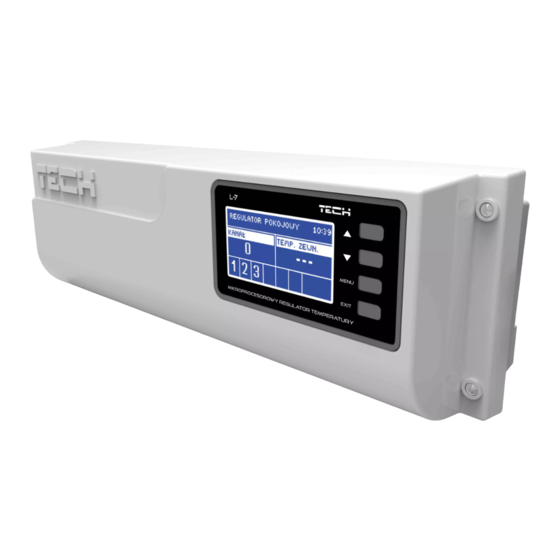
Page 4: Device Description
II. DEVICE DESCRIPTION EU-L-7E external controller is intended for controlling valves. The controller enables significant energy saving due to precise temperature management in particular rooms. Thanks to advanced software the controller fulfils a wide range of functions: • possibility of controlling up to 22 thermostatic actuators via 8 room sensors (C-7p): •... -
Page 5: Installation
III. INSTALLATION EU-L-7E controller should be installed by a qualified person. The device is intended to be a free-standing unit or a wall- mountable panel. WARNING Risk of fatal electric shock from touching live connections. Before working on the controller switch off the power supply and prevent it from being accidentally switched on. -
Page 6: First Start-Up
In order for the controller to operate correctly, the user must follow these steps when starting the device for the first time Step 1. Connect EU-L-7E controller with the devices Remove the cover and connect the wires following the clues on the connectors and the diagrams presented below. - Page 8 Pictorial diagram presenting wiring and communication with other devices in the system: Step 2. Mounting electrolytic capacitors In order to reduce the phenomenon of fluctuation in the temperature read from the zone sensor, use a 220uF / 25V low impedance electrolytic capacitor (GF 220U / 25V SAMXON) connected parallel to the sensor cable. When installing a capacitor, pay special attention to polarization.
- Page 9 Step 4. Activate the Internet module EU-L-7E external controller is compatible with ST-507 Internet module and WiFi RS. WiFi RS uses WiFi wireless network whereas ST-507 needs to be connected to a router with RJ45 network cable. Connection diagram for ST-507 Internet module Connection diagram for WiFi RS Internet module ST-507 Internet module or WiFi RS should be connected as illustrated in the diagrams above.
-
Page 10: Main Screen Description
Set current time and date in the fitter’s menu. Step 6. Configure the settings for temperature sensors, room regulators To enable EU-L-7E to control a given zone, it is necessary to provide it with current temperature value. The easiest way is to use C-7p temperature sensor. - Page 11 MAIN SCREEN 1. Current mode (flame– heating, snowflake – cooling) 2. An icon indicating pump operation 3. Voltage-free contact 4. Current time 5. Time left until the manually set temperature in a given zone changes 6. Information about the type of current weekly schedule 7.
-
Page 12: Controller Functions
MIXING VALVE SCREEN 1. Valve opening 2. External temperature rounded to whole degrees 3. Current mode (flame– heating, snowflake – cooling) 4. An icon indicating pump operation 5. Voltage-free contact 6. Current time 7. Current valve temperature 8. Pre-set valve temperature 9. -
Page 13: Screen View
SCREEN VIEW In this submenu the user may change the main screen view: • Main screen – including zones parameters e.g. pre-set temperature, current temperature etc. • Mixing valve screen – including mixing valve operation parameters. MANUAL MODE This function enables the user to activate particular devices (pump, voltage-free contact and valve actuators) independently of the others in order to check if they operate properly. -
Page 14: Zones
Hysteresis OFF/ON After the room sensor has been connected and registered in a given zone, it is used by EU-L-7E controller. The default setting for this option is <OFF>. It may be activated when the room sensor has been connected. -
Page 15: Operation Mode
Schedule 1-5 – global schedule These schedules have universal settings for all zones and they cannot be edited in the external controller (to introduce changes it is necessary to use M-7 control panel or connect to the Internet via the Internet module). In order to assign a schedule to a given zone, choose Select option. - Page 16 Registration Pre-set valve temperature Valve status Temperature monitoring Opening time Single stroke Valve Minimum opening Valve type Weather-based control Return protection External sensor correction Factory settings Valve removal Registration Software version DHCP Internet module IP address IP mask Gate address DNS address Module version TECH regulator...
-
Page 17: Valve
VALVE EU-L-7E external controller may control an additional valve via valve module (e.g. ST-431N). The devices communicate using RS communication but it is necessary to register first. Registration - Configuring particular parameters of additional valve is possible only after it has been properly registered by entering the module number (the number may be found at the back of the control module cover or in Software version submenu). -
Page 18: Internet Module
IP address, IP mask, gateway address and DNS address from the local network. The Internet module may be connected to EU-L-7E via RS cable. Detailed description of the procedure is available in the Internet module instruction manual. -
Page 19: Own Schedule Settings
IX. OWN SCHEDULE SETTINGS Once the schedule has been selected (Menu -> Zones -> Zone 1-8 -> Weekly control), the user may select, view and edit a given schedule. Schedule view screen: 1. Time periods. 2. Pre-set temperature for time periods. 3. - Page 20 Use arrows UP and DOWN to define the pre-set temperature for the first time period. Press MENU to confirm. Once the time periods are ready, use arrows UP and DOWN to define the pre-set temperature which will apply outside these periods.
-
Page 21: Protections And Alarms
X. PROTECTIONS AND ALARMS In order to ensure safe and failure-free operation, the regulator has been equipped with a range of protections. In case of an alarm, a sound signal is activated and the display shows a message informing about the detected problem. Automatic sensor control In the event of temperature sensor damage an alarm is activated informing the user about the type of failure e.g. - Page 23 EU Declaration of conformity Hereby, we declare under our sole responsibility that EU-L-7E manufactured by TECH, headquartered in Wieprz Biała Droga 31, 34-122 Wieprz, is compliant with: • Directive 2014/35/EU of the European Parliament and of the Council of February 26, 2014 on...
Need help?
Do you have a question about the EU-L-7E and is the answer not in the manual?
Questions and answers