Table of Contents
Advertisement
Quick Links
Advertisement
Table of Contents

Related Manuals for Tech Controllers EU-801 PID


Summary of Contents for Tech Controllers EU-801 PID
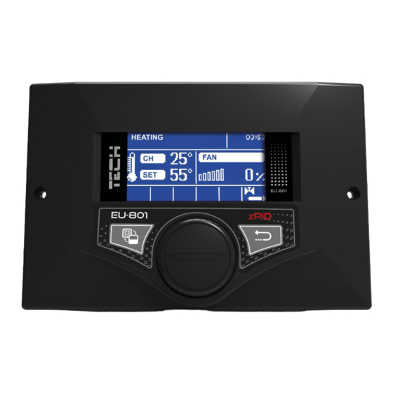
- Page 1 EU-801 PID...
-
Page 3: Table Of Contents
ABLE ONTENTS Safety ......................................5 Description of the device ................................6 How to install the controller ............................... 6 How to use the controller ................................8 Principle of operation ................................ 9 Controller functions – main menu .............................. 9 Fire-up/ extinguishing ..............................10 Screen view .................................. - Page 4 6.5.2 CH boiler control ................................. 23 Operation algorithm ................................ 23 6.6.1 Standard ..................................23 6.6.2 PID ....................................23 Buffer parameters ................................24 6.7.1 Buffer ..................................25 6.7.2 Pre-set temperature top ............................. 25 6.7.3 Pre-set temperature bottom ............................25 6.7.4 DHW function ................................25 Pump activation temperature ............................
-
Page 5: Safety
AFETY Before using the device for the first time the user should read the following regulations carefully. Not obeying the rules included in this manual may lead to controller damage. In order to avoid accidents and errors, it should be ensured that every person using the device has familiarized themselves with the principle of operation as well as security functions of the controller. -
Page 6: Description Of The Device
ESCRIPTION OF THE DEVICE The EU-801 PID controller is intended for wood gasification CH boilers equipped with an exhaust fan. Due to advanced software, the controller fulfils a range of functions: • control of fan • control of central heating pump - CH •... -
Page 8: How To Use The Controller
OW TO USE THE CONTROLLER During standard operation of the controller, graphic display shows the main page. Depending on the operation mode, a corresponding main screen is displayed. By pressing pulser knob the user enters the first level menu. The display shows the first options of the menu. In order to move on to the next option, twist the pulser knob. -
Page 9: Principle Of Operation
RINCIPLE OF OPERATION The ST–801 PID temperature regulator is intended for wood gasification CH boilers. It controls water circulation pump, DHW pump and additional pump. It may also cooperate with 2 three- or four-way valves, a room regulator, GSM module and Ethernet module. -
Page 10: Fire-Up/ Extinguishing
EXTINGUISHING This function enables the user to easily fire up the CH boiler. After the fire is initiated, the user activates automatic fire-up function. Owing to optimum parameters the CH boiler smoothly switches to operation mode with the use of the PID function. When the CH boiler enters the fire-up mode, this option changes to Extinguishing. -
Page 11: Pause In Sustain Mode
5.4.3 PAUSE IN SUSTAIN MODE This option is used to configure the pause time of the fan in sustain mode. NOTE Incorrect settings may lead to constant temperature increase! Pause in sustain mode should not be too short. 5.4.4 FAN SPEED IN SUSTAIN MODE This option is used to adjust the fan speed (blow force) in sustain mode. -
Page 12: Summer Mode
CH temperature, alternately with Pre-set). It also indicates that the weekly control function is active. How to change weekly control settings: The EU-801 PID regulator offers two ways of configuring weekly control: MODE 1 – the user sets the temperature deviations for each day of the week separately;... -
Page 13: Fitters Menu
5.11 S ERVICE MENU In order to access service settings of the EU-801 PID controller, it is necessary to enter a 4-digit code provided by TECH. 5.12 L ANGUAGE This option is used to select the controller language version. -
Page 14: Controller Functions - Fitter's Menu
– ’ ONTROLLER FUNCTIONS FITTER S MENU Fitter’s menu is intended to be accessed by a qualified person. It includes additional controller functions such as CH boiler parameters, additional valves, additional pumps as well as advanced settings of basic functions (e.g. parameters of built-in valves). -
Page 15: Valve Settings
ALVE SETTINGS The EU-801 PID controller has a built-in module controlling the mixing valve. It is possible to connect two additional valve- controlling modules. There is a range of parameters allowing the user to adjust the valve operation to the individual needs.Once a valve has been enabled, the display shows an additional menu with valve parameters. - Page 16 6.1.1.1 VALVE STATUS With this option the user may enable or disable the valve. 6.1.1.2 PRE-SET TEMPERATURE This parameter defines the desired temperature which the valve should maintain. During proper operation, the temperature of water downstream of the valve approaches the pre-set value. 6.1.1.3 OPENING TIME This parameter defines the time needed for the valve to open from 0% to 100% position.
- Page 17 Example: Pre-set CH boiler temperature 55°C Room reg. temp. lower 15°C Minimum pre-set CH boiler temperature 45°C Pre-set CH boiler temperature after pre-set room temperature has 45°C been reached Once the pre-set flat temperature has been reached (signalised by the room regulator), the pre-set CH boiler temperature will be reduced to 45°C, which is only by 10°C although the Room reg.
- Page 18 6.1.1.6 WEATHER-BASED CONTROL ON/OFF WEATHER- BUILT-IN VALVE, BASED VALVE 1,2 CONTROL Heating curve For the function of weather control to be active, the external sensor mustn't be exposed to sunlight or influenced by weather conditions. After it has been installed and connected, weather-based control function needs to be activated in the controller menu.
- Page 19 6.1.1.8 RETURN PROTECTION This function allows setting up CH boiler protection against too cool water returning from the main circulation, which could cause low-temperature boiler corrosion. The return protection involves closing the valve when the temperature is too low, until the short circulation of the boiler reaches the appropriate temperature.
-
Page 20: Room Reg Temp Lower
6.1.1.15 ADDITIONAL SENSORS Option available for valves 1,2. When two mixing valves are used, this function enables the user can select the sensors which will provide temperature data for the valve (for external and return temperature sensors). Temperatures can be read from the sensors of a given valve (own) or the sensors of valve 2 (from module 2). -
Page 21: Ethernet Module
THERNET MODULE DHCP IP address DNS address FITTER’S ETHERNET ON/OFF Gate address MENU MODULE DNS address Version Register Before registering the module, it is necessary to create user’s account on emodul.pl (if you do not have one). Once the module has been connected properly, select Module ON. ... -
Page 22: Room Regulator
ROOM MENU REGULATOR TECH RS regulator (ON/OFF) This function enables the user to select the type of regulator connected to the EU-801 PID controller and configure the room regulator operation. 6.5.1 CH PUMP CONTROL This function enables the room regulator to influence the operation of the CH pump. When this function is active, the CH pump... -
Page 23: Ch Boiler Control
6.6.2 The EU-801 PID is a controller with continuous output signal, using PID control algorithm. This type of controller calculates the fan speed on the basis of CH boiler temperature and the flue gas temperature measured at the CH boiler outlet. The fan operates continuously and the fan blow force depends on the CH boiler temperature, the flue gas temperature as well as the difference between these parameters and their pre-set values. -
Page 24: Buffer Parameters
TEST RESULTS - TECH controller with PID control: TEST RESULTS - TECH controller without PID control: All remarks concerning the software should be reported to the CH boiler manufacturer. Each controller should be customized to individual needs, depending on the type of fuel and CH boiler used. TECH does not accept responsibility for incorrect configuration of the controller settings. -
Page 25: Buffer
6.7.1 BUFFER Once the buffer function has been activated (by selecting ON), the CH pump serves as pump of the buffer in which two sensors are installed: upper sensor (C1) and lower sensor (C2). The pump remains active until the pre-set parameters are reached. When the temperature drops below the pre-set buffer top temperature, the pump is activated again. -
Page 26: Additional Heat Source
6.10 A DDITIONAL HEAT SOURCE This option is available only in Standard operation mode. Using this option the user may enable or disable the additional heat source. 6.11 A DDITIONAL PUMP CH pump CH boiler protection ADDITIONAL Circulating pump FITTER’S MENU PUMP Short circuit pump Valve pump... -
Page 27: 6.11.3 Circulating Pump
6.11.2.2 MAXIMUM TEMPERATURE This parameter define the temperature at which the pump will be disabled. 6.11.2.3 SENSOR SELECTION It allows the user to decide which sensor should provide data for activation of the additional pump: CH sensor, DHW sensor, valve 1 sensor, return sensor, weather sensor, buffer sensor top, buffer sensor bottom. 6.11.3 CIRCULATING PUMP When this function is active, the additional pump serves as the circulating pump. -
Page 28: Pump Anti-Stop
After this function is activated (it is possible only in Water tank priority mode), the water tank is heated until the pre-set temperature of 70°C is reached (default setting). The temperature is maintained for the whole disinfection time (default setting: 10 minutes). -
Page 29: Protections
ROTECTIONS In order to ensure safe and failure-free operation, the regulator has been equipped with a range of safeguards. In case of alarm, a sound signal is activated and the display shows an appropriate message. In order for the controller to return to the operation mode, press pulser knob. In the case of CH temperature too high alarm, it is necessary to wait until the temperature drops below the alarm value. -
Page 30: Fuse
ECHNICAL DATA Before and during the heating season, the EU-801 PID controller should be checked for condition of its cables. The user should also check if the controller is properly mounted and clean it if dusty or dirty. It is advisable to measure earthing parameters for the motors (CH pump, DHW pump and fan). - Page 31 EU DECLARATION OF CONFORMITY Hereby, we declare under our sole responsibility that EU-801 PID manufactured by TECH, head-quartered in Wieprz Biała Droga 31, 34-122 Wieprz, is compliant with Directive 2014/35/EU of the European Parliament and of the Council of 26 February 2014 on the harmonisation of the laws of Member States relating to the making available on the market of electrical equipment designed for use within certain voltage limits (EU OJ L 96, of 29.03.2014, p.
Need help?
Do you have a question about the EU-801 PID and is the answer not in the manual?
Questions and answers