Table of Contents
Advertisement
Quick Links
Advertisement
Table of Contents

Related Manuals for Tech Controllers EU-3910 SIGMA


Summary of Contents for Tech Controllers EU-3910 SIGMA
- Page 1 EU-3910 SIGMA...
-
Page 2: Table Of Contents
TABLE OF CONTENTS Safety ..................................3 Device description ..............................4 How to install the controller ............................4 How to use the controller ............................6 Main screen description ............................. 7 Principle of operation – stages of controller operation ..................... 7 6.1 Fire-up ..................................7 6.2 Operation ................................. -
Page 3: Safety
AFETY Before using the device for the first time the user should read the following regulations carefully. Not obeying the rules included in this manual may lead to controller damage. In order to avoid accidents and errors, it should be ensured that every person using the device has familiarized themselves with the principle of operation as well as security functions of the controller. -
Page 4: Device Description
EVICE DESCRIPTION The EU-3910 SIGMA temperature regulator with a throttle is intended for controlling the burning process in a home air fireplace. The regulator enables the user to control an additional device via a voltage-free contact. Controller functions: • Control of a throttle •... - Page 5 Connection diagram: 1. Voltage-free contact 2. Temperature sensor 3. Throttle 4. Control panel 5. Internet module Pictorial diagram - controller operation: 1. Voltage-free contact 2. Temperature sensor 3. Throttle 4. Control panel...
-
Page 6: How To Use The Controller
OW TO USE THE CONTROLLER 1. Controller display 2. EXIT – in the controller menu the button is used to exit the menu or cancel the settings. in the main screen view it is used to decrease the pre-set temperature. In the controller menu it is used to –... -
Page 7: Main Screen Description
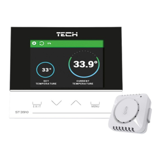
AIN SCREEN DESCRIPTION 1. Controller operation mode (x – extinguished) 2. Opening degree of throttle 3. Current room temperature 4. Pre-set room temperature – RINCIPLE OF OPERATION STAGES OF CONTROLLER OPERATION The user starts the fire-up function by pressing a corresponding icon. The other modes start automatically, depending on the stage of the controller operation. -
Page 8: Extinguishing
XTINGUISHING During blow-by stage, the throttle closes and opens at pre-defined intervals (Service menu). After blow-by stage, the controller status switches to extinguished. The extinguishing process may also be activated by disabling the throttle in the main menu. AIN MENU LOCK DIAGRAM MAIN MENU Fire up (Throttle on/off... -
Page 9: Fire-Up (Throttle On/Off)
THROTTLE ON The aim of this function is to achieve optimum flame in the shortest time possible.The fire-up effectiveness is enhanced by throttle operation. This stage lasts until room temperature reaches a pre-defined value required to enter the operation mode. Once the controller enters operation mode, instead of Fire-up function, Throttle ON/OFF appears in the menu. -
Page 10: Language
ANGUAGE This function enables the user to change the language version of the controller. CREEN SETTINGS These parameters are used to adjust the screen layout. • Screen brightness – This parameter is used to adjust screen brightness during operation. • Blank screen brightness –... -
Page 11: Fitter's Menu
’ ITTER S MENU INTERNET MODULE Internet module is a device enabling the user remote control of the heating system. The user can control the status of all system devices on the screen of a home computer, tablet or mobile phone. In addition to the possibility of viewing the temperature of each sensor, the user has the option of changing the temperature values. -
Page 12: Sensor Registration
ENSOR REGISTRATION The function allows the user to register an additional sensor. To register, select this function and press the registration (communication) button on the sensor. NOTE Up to 8 additional sensors can be registered to the controller. IST OF SENSORS By selecting this function, the user can view the registered sensors. - Page 13 Once the module has been connected properly, select Module ON. Next, select Registration. The controller will generate a code. Log on emodul.pl, go to Settings tab and enter the code which appeared on the controller screen. It is possible to assign a name or description to the module as well as provide phone number and e-mail address to which the notifications will be sent.
-
Page 14: Technical Data
10 T ECHNICAL DATA Specification Value Power supply 230V ± 10% / 50Hz Maximum power consumption 230V AC / 0,5A (AC1) * Potential-free cont. nom. out. load 24V DC / 0,5A (DC1) ** Ambient temperature 5°C ÷ 50°C Thermal resistance of NTC sensor -30°C ÷... - Page 15 EU DECLARATION OF CONFORMITY Hereby, we declare under our sole responsibility that EU-3910 SIGMA manufactured by TECH, head-quartered in Wieprz Biała Droga 31, 34-122 Wieprz, is compliant with Directive 2014/35/EU of the European Parliament and of the Council of 26 February 2014 on the harmonisation of the laws of Member States relating to the making available on the market of electrical equipment designed for use within certain voltage limits (EU OJ L 96, of 29.03.2014, p.
Need help?
Do you have a question about the EU-3910 SIGMA and is the answer not in the manual?
Questions and answers