Table of Contents
Advertisement
Quick Links
Advertisement
Table of Contents

Related Manuals for Tech Controllers EU-L-8e


Summary of Contents for Tech Controllers EU-L-8e
- Page 1 EU-L-8e...
-
Page 2: Table Of Contents
TABLE OF CONTENTS Safety ..................................4 Device description ..............................5 III. How to install the controller ............................. 5 First start-up ................................6 Wireless communication ............................12 Main screen view and description .......................... 14 Sensors screen .................................. 17 VII. Controller functions ..............................18 Block diagram –... - Page 3 11.1. Registration ................................24 11.2. Sensor removal ..............................25 11.3. Settings ................................25 Menu ..................................25 Block diagram – fitter’s menu ............................25 Internet module ................................25 Operation delay ................................26 3.1. Voltage-free contact ............................26 3.2. Pump ..................................26 Pump anti-stop ................................
-
Page 4: Safety
SAFETY Before using the device for the first time the user should read the following regulations carefully. Not obeying the rules included in this manual may lead to personal injuries or controller damage. The user’s manual should be stored in a safe place for further reference. -
Page 5: Device Description
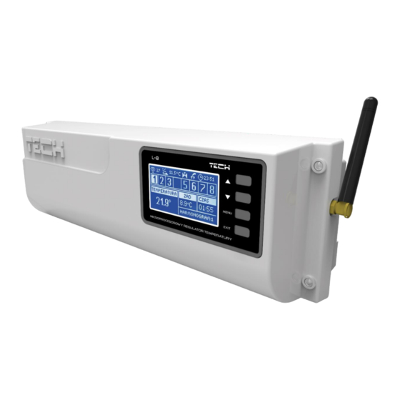
II. DEVICE DESCRIPTION EU L-8 external controller is intended for both wired and wireless control of the valves (see: Wireless communication). The controller enables significant energy saving due to precise temperature management in particular rooms. Due to advanced software, the controller fulfils a wide range of functions: •... -
Page 6: First Start-Up
WARNING The controller may be installed on a DIN strip. IV. FIRST START-UP Follow these step while starting the device for the first time to ensure its failure-free operation: Step 1. Connect L-8 controller with all the devices to be controlled In order to connect the cables, remove the controller cover and connect the cables as indicated on connector labels and diagrams below: All the necessary valve actuators ST-230/2 (connectors 1-8) - Page 7 Pictorial diagram presenting wiring and communication with other devices in the system:...
- Page 9 Step 2. Switch on the power supply and check if the devices work properly Once all the devices has been connected, switch on the power supply. Use the Manual mode function to check if each device works properly – use the buttons ▲ and ▼ to select the device and press MENU button - the device should be activated.
- Page 10 NOTE The user should enable the Internet module to connect with data servers listening on TCP/2000 port. Most computer networks are protected by various software (firewalls, anti-virus software etc.) which may block data exchange with the above mentioned port. If any problems arise, contact technical support or your computer network administrator. Step 4.
- Page 11 Step 7. Configure the settings for the temperature sensors and the room regulators To enable EU L-8 external controller to control a given zone, it is necessary to provide it with current temperature value. The easiest way is to use C-8r temperature sensor. If the user wants to be able to change the pre-set temperature value directly from the zone, it is advisable to use R-8b, R-8z room regulators.
-
Page 12: Wireless Communication
V. WIRELESS COMMUNICATION EU L-8 external controller may communicate with certain devices using radio signal: Device Function How to configure The sensor should be Sending current room C-8-r – room temperature registered in the external temperature data sensor controller The sensor should be C- mini - room temperature Sending current room registered in the external... - Page 13 STT-869 – wireless The actuator should be - Opening/closing the valve in thermostatic actuator registered in the external order to maintain desired controller temperature value The sensor should be installed - It sends information to the in the window of a given zone C-2 –...
-
Page 14: Main Screen View And Description
VI. MAIN SCREEN VIEW AND DESCRIPTION The user navigates in the menu structure using the buttons located next to the display. Display. ▲ - „up” „plus” - it is used to view the menu options and increase the value while editing parameters. During standard operation the button is used to switch between different zones parameters. - Page 15 ZONE SCREEN Current day of the week Pump ON Voltage-free contact ON Current time Current weekly schedule C-8r battery level in a given zone (backlit numer in the zone bar – see: description np.12) C-8r sensor signal strength in a given zone (backlit numer in the zone bar – see: description no.12) Pre-set temperature in a given zone (blacklit numer in the zone bar –...
- Page 16 ZONE SCREEN C-8r sensor signals strength in a given zone Pump ON Voltage-free contact ON Pre-set temperature in a given zone C-8r sensor battery level in a given zone Current time Current weekly schedule Current room temperature in a given zone Current floor temperature in a given zone 10.
-
Page 17: Sensors Screen
SENSORS SCREEN Current day of the week External temperature Pump ON Voltage-free contact ON Current time Current temperature in zone 3 3 Pre-set temperature in zone 3 Floor temperature in zone 4 Current schedule: • G1 – global schedule 1 •... -
Page 18: Controller Functions
VII. CONTROLLER FUNCTIONS BLOCK DIAGRAM – CONTROLLER MENU Normal mode Holiday mode Operation mode Economical mode Zones Comfort mode Registration External sensor Sensor type Valves 1-8 Manual mode Voltage-free contact Pump Automatic Time settings Clock settings Date settings Screensaver Button sounds Screen view Screen settings Display contrast... -
Page 19: Operation Mode
OPERATION MODE This function enables the user to select the operation mode for a given zone. • Normal mode – pre-set temperature depends on the selected schedule. • Holiday mode pre-set temperature depends on Temperature settings parameters (Menu > Zones > User settings > Temperature settings >... -
Page 20: Language
The user may also adjust the display contrast and screen brightness. <Screen blanking> function is used to adjust the blank screen brightness. <Screen blanking time> parameter defines the time of inactivity after which the screen goes blank. LANGUAGE This option is used to select the language version. FITTER’... -
Page 21: Zones
VIII. ZONES BLOCK DIAGRAM – ZONES MENU Type of sensor Pre-set temperature Heating Schedule Cooling Floor pump Heating Cooling User settings Weather-based control Temperature settings Registration Floor heating Operation mode Hysteresis Calibration Registration Actuators Actuator removal Settings Registration Window sensors Sensor removal Settings This submenu enables the user to configure operation parameters for particular zones. -
Page 22: Type Of Sensor
After the room sensor has been activated and registered in a given zone, it is used by L-9 controller. The function is inactive by default, but it may be activated when the room sensor has been register. TYPE OF SENSOR This function is used to select the wired or wireless sensor type. -
Page 23: Floor Heating
FLOOR HEATING 7.1. REGISTRATION Activate Registration option in L-8 external controller and press the communication button in the selected floor temperature sensor C-8f. If the registration has been completed successfully, L-8 display will show an appropriate message and C-8f control light will flash twice to confirm. -
Page 24: Window Sensors
Example: Pre-set zone temperature: 23˚C Minimum opening: 30% Maximum opening: 90% Range: 5˚C Hysteresis: 2˚C With the above settings, the valve starts closing if the zone temperature reaches 18˚C (the pre-set value minus range: 23-5). The minimum opening is reached when the zone temperature reaches the pre-set value. After the pre-set value has been reached, the zone temperature starts falling. -
Page 25: Sensor Removal
11.2. SENSOR REMOVAL This function is used to remove the sensors from a given zone. 11.3. SETTINGS • ON – this function is used to enable the window sensor (it is possible only after the sensor has been registered). • Delay time –... -
Page 26: Operation Delay
After switching the module on and selecting DHCP option, the controller automatically downloads such parameters as IP address, IP mask, gateway address and DNS address from the local network. If any problems arise when downloading the network parameters, they may be set manually. The procedure of obtaining these parameters is described in detail in the instruction manual of the Internet Module. -
Page 27: Maximum Humitidy
MAXIMUM HUMITIDY If the current humidity level is higher than the maximum humidity, cooling will be disabled in a given zone. NOTE This function is active in the Cooling mode when the humidity protection function is switched on (Menu -> Zone - >... -
Page 28: Valve Type
8.8. VALVE TYPE This option is used to select the valve type: • CH – select this option if you want to control CH circulation temperature. • FLOOR – select this option if you want to control the floor heating temperature. It protects the underfloor heating installation against dangerous temperature. -
Page 29: Factory Settings
8.14. FACTORY SETTINGS This parameter is used to restore the factory settings of a given valve. FACTORY SERRINGS This function enables the user to restore the valve settings saved by the manufacturer. X. OWN SCHEDULE SETTINGS Once the schedule has been selected (Menu -> Zones -> Zone 1-8 -> Weekly control), the user may select, view and edit a given schedule. -
Page 30: Unregister A Single Actuator
• Use arrows UP and DOWN to select the pre-set temperature to apply outside the time periods. Confirm by pressing MENU. • Use arrows UP and DOWN to select the starting time of the first time period. Confirm by pressing MENU. •... -
Page 31: Protections And Alarms
XII. PROTECTIONS AND ALARMS In order to ensure safe and failure-free operation, the regulator has been equipped with a range of protections. In case of an alarm, a sound signal is activated and the display shows a message informing about the detected problem. Type of alarm Possible cause How to fix it... - Page 32 - Call the service staff - Replace the batteries Error #3 - Calibration error 3 - - The valve stroke is too small or the - Call the service staff valve dimensions are not typical The screw has not been pulled out enough - Actuator current sensor is damaged - the screw meets resistance...
-
Page 33: Software Update
Fuse The regulator has a WT 6,3A tube fuse-link (5x20mm) protecting the network. NOTE Higher amperage fuse should not be used as it may damage the controller. XIII. SOFTWARE UPDATE In order to install new software, the controller must be unplugged from the power supply. Next, insert the memory stick with the new software into the USB port. - Page 34 EU Declaration of Conformity Hereby, we declare under our sole responsibility that EU-L-8e manufactured by TECH STEROWNIKI II Sp. z o.o., head- quartered in Wieprz Biała Droga 31, 34-122 Wieprz, is compliant with Directive 2014/53/EU of the European parliament and of the Council of 16 April 2014 on the harmonisation of the laws of the Member States relating to the making available...
Need help?
Do you have a question about the EU-L-8e and is the answer not in the manual?
Questions and answers