Table of Contents
Advertisement
Advertisement
Table of Contents

Related Manuals for Tech Controllers EU-L-9r


Summary of Contents for Tech Controllers EU-L-9r
- Page 1 EU-L-9r...
-
Page 2: Table Of Contents
SPIS TREŚCI Safety ....................................5 Device Description ................................6 III. How to install the controller ............................6 First start-up ..................................6 Main screen view and description ..........................14 Controller functions ............................... 16 Block diagram – controller menu ..........................16 Operation mode ................................16 Zones .................................... - Page 3 5.7. Calibration ................................21 Hysteresis ..................................21 Calibration ..................................21 Thermostatic actuators ..............................21 8.1. Registration ................................21 8.2. Valve actuators ..............................21 8.3. Information ................................21 8.4. Settings ................................21 Window sensors ................................22 9.1. Registration ................................22 9.2. Sensor removal ..............................
- Page 4 Humidity protection ..............................28 Factory settings ................................28 Schedule settings ................................28 Software update ................................30 Technical data ................................30 XII. Protections and alarms ..............................30 KN.17.01.2020...
-
Page 5: Safety
SAFETY Before using the device for the first time the user should read the following regulations carefully. Not obeying the rules included in this manual may lead to personal injuries or controller damage. The user’s manual should be stored in a safe place for further reference. -
Page 6: Device Description
STT-868 or STT-869 actuators (up to 6 per zone) III. HOW TO INSTALL THE CONTROLLER EU-L-9r controller should be installed by a qualified person. It may be installed as a free-standing device or as a panel mountable on a wall. - Page 7 Pictorial diagram of wiring up and communication between the devices in the system:...
- Page 8 Scheme illustrating connection and communication between devices in the system using RJ jack:...
- Page 9 Scheme illustrating connection and communication between devices in the system using a pluggable terminal block:...
- Page 11 Krok 4. How to configure temperature sensors or a control panel To enable EU-L-9r external controller to control a given zone, it is necessary to provide it with current temperature value. The easiest way is to use temperature sensor EU-C-8r, EU-R-8b or EU-C-mini. If the user wants to be able to change the pre-set temperature value directly from the zone, it is advisable to use EU-R-9b, EU-R-9s or EU-R-9z.
- Page 12 How to connect sensors and room regulators:...
-
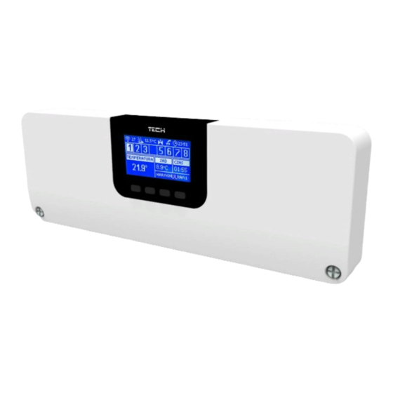
Page 14: Main Screen View And Description
V. MAIN SCREEN VIEW AND DESCRIPTION The user navigates in the menu structure using the buttons located next to the display. 1. Display 2. ▲- „up” „plus” – it is used to view the menu options and increase the value while editing parameters. During standard operation the button is used to switch between different zones parameters. - Page 15 1. Current day of the week 2. External temperature 3. Pump ON 4. Voltage-free contact ON ( (heating = flame icon; cooling = fan icon). 5. Current time 6. Current operation mode in the zone 7. Sensor battery level in a given zone (highlighted number on the zone information bar - description no. 12). 8.
-
Page 16: Controller Functions
9. Current floor temperature in the given zone 10. Maximum and minimum floor temperature 11. Information about the number of window sensors registered in a given zone 12. Information about the number of thermostatic actuators registered in a given zone 13. -
Page 17: Zones
This function enables the user to activate a given operation mode in the zone. Normal mode – pre-set temperature depends on the selected schedule. Holiday mode – the pre-set temperature depends on ‘Temperature settings’ parameter ( Menu > Zones > User’s settings >... -
Page 18: Time Settings
This submenu enables the user to configure operation parameters for particular zones. When the pre-set temperature value in a zone is reached, EU-L-9r controller labels the zone as sufficiently heated and the status remains unchanged until the temperature drops below the pre-set temperature by hysteresis value. When the temperature in all the zones is sufficient, the controller disables both the pump and the voltage-free contact. -
Page 19: Operation Mode
OPERATION MODE In this submenu, the user can view, edit or set the operation mode in a given zone. It is also possible edit weekly schedules here. The user may set 6 weekly schedules in a given zone: 1 local schedule and 5 global schedules. The schedule temperature settings are common for heating and cooling;... -
Page 20: Floor Heating
Select ‘Registration’ in L-9r controller and press the communication button in the selected floor temperature sensor C-8f. If the registration has been successful, the EU-L-9r display will show an appropriate message and the control light on C-8f sensor will flash twice. -
Page 21: Calibration
If the floor temperature exceeds the pre-set maximum temperature, the relay will be disconnected and the floor heating will be disabled. The relay will be connected again when the floor temperature drops to the maximum temperature minus hysteresis. Example 2 – Comfort mode: Minimum floor temperature:23°C Hysteresis: 2°C When the floor temperature reaches 23°C, the relay is connected. -
Page 22: Window Sensors
WINDOW SENSORS 9.1. REGISTRATION In order to register a sensor, select Registration option in the controller EU-L-9r and quickly press the communication button on the window sensor. Release the button and watch the control light. the control light flashes twice - successful communication ... -
Page 23: Sensor Removal
9.2. SENSOR REMOVAL This function is used to remove the sensors from a given zone. 9.3. INFORMATION After this option has been selected, the display shows information about the actuator version, battery level, range and the actuator opening level (%). 9.4. -
Page 24: Pump
1.1. PUMP EU-L-9r controls the pump operation - it enables the pump after the pre-defined delay time if any of the zones has not reached the pre-set temperature. When all the zones reach the pre-set temperature, the pump is disabled. -
Page 25: Valve Settings
VALVE SETTINGS EU-L-9r may control an additional valve via a valve module (e.g. i-1m). The regulators connect using RS communication but the registration process is necessary. There is a range of parameters enabling the user to adjust the valve operation to individual needs. -
Page 26: Valve Type
Valve stops at 50°C Valve closing 52°C Valve opening 48°C When the pre-set temperature is 50°C and the hysteresis value is 2°C, the valve stops in one position when the temperature of 50°C is reached. When the temperature drops to 48°C, the valve starts opening. When the temperature of 52°C is reached, the valve starts closing in order to reduce the temperature. -
Page 27: Opening Direction
4.13. OPENING DIRECTION If, after connecting the valve to the controller, it turns out that it is connected the other way round, then the power supply cables do not have to be switched. Instead, it is enough to change the opening direction in this parameter: LEFT or RIGHT. 4.14. -
Page 28: Factory Settings
4.17. FACTORY SETTINGS This parameter is used to restore the factory settings of a given valve. HUMIDITY PROTECTION If the current humidity value is higher than the pre-set maximum humidity (fitter’s menu -> protection - humidity -> Maximum humidity), cooling in the given zone will be disabled. The function is activated for particular zones (Zones -> Zone 1 -> User settings ->... - Page 29 - Use arrows UP and DOWN to select <Assign days>. Press MENU in order to edit. - Use arrows UP and DOWN to switch between days. Confirm by pressing MENU. Active days are highlighted in white. - In order to confirm the settings, press EXIT and select <Confirm> and move on to editing daily schedule.
-
Page 30: Software Update
X. SOFTWARE UPDATE In order to install new software, the controller must be unplugged from the power supply. Next, insert the memory stick with the new software into the USB port. Connect the controller to the power supply at the same time holding EXIT button. It is necessary to hold EXIT button until a single sound signal is heard –... - Page 31 After the communication is reestablished, the alarm is deactivated automatically. STT-868 actuator alarm ERROR #0 Flat battery in the actuator Replace the batteries ERROR #1 Some parts have been damaged Call the service staff - No piston controlling the valve - Install a piston controlling the actuator ERROR #2 - Too big stroke (movement) of the valve...
- Page 32 ERROR #5 – Low battery level The battery is fl at Replace the batteries ERROR #6 – Encoder is The encoder is damaged Call the service staff locked - Unevenness of the screw, the thread etc. ERROR #7 – To high voltage Call the service staff may cause excessive resistance...
- Page 33 EU Declaration of conformity Hereby, we declare under our sole responsibility that EU-L-9r manufactured by TECH, headquartered in Wieprz Biała Droga 31, 34-122 Wieprz, is compliant with: • Directive 2014/35/EU of the European Parliament and of the Council of February 26, 2014 on the harmonisation of the laws of Member States relating to the making available on the market of electrical equipment designed for use within certain voltage limits (EU Journal of Laws L 96, of 29.03.2014, p.
Need help?
Do you have a question about the EU-L-9r and is the answer not in the manual?
Questions and answers