Table of Contents
Advertisement
Quick Links
Advertisement
Table of Contents

Summary of Contents for Tech Controllers EU-427i
- Page 1 fwybór...
-
Page 3: Table Of Contents
ABLE OF CONTENTS Safety ................................4 Description of the control panel ........................5 Screen view– icons: ..........................6 Principle of operation ...........................6 Controller functions ............................7 Manual operation ..........................7 Parameters P1/P2/P3 ..........................7 4.2.1 Operation type ..........................7 Priorities ............................. 10 Programmes ............................10 Sensors ............................... 11 Pump operating time counter ...................... -
Page 4: Safety
AFETY Before using the device for the first time the user should read the following regulations carefully. Not obeying the rules included in this manual may lead to personal injuries or controller damage. The user’s manual should be stored in a safe place for further reference. In order to avoid accidents and errors it should be ensured that every person using the device has familiarized themselves with the principle of operation as well as security functions of the controller. -
Page 5: Description Of The Control Panel
ESCRIPTION OF THE CONTROL PANEL Pump 1 Pump 2 Pump 3 Stadnby mode Exit button – to exit, or discard settings Pulser knob – to enter MENU, select and confirm settings... -
Page 6: Screen View- Icons
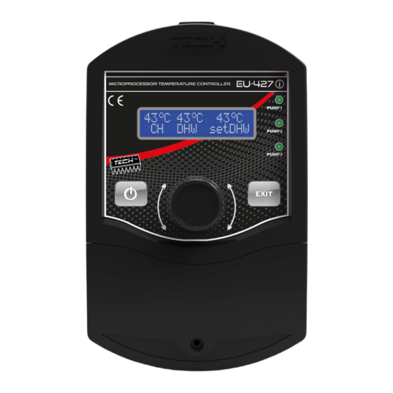
RINCIPLE OF OPERATION The intended use of EU-427i controller is to control the operation of max. 3 pumps at a time. The user can select one of the three pumps: central heating pump, domestic hot water pump or circulation pump. The controller turns the selected pump on or off depending on if the specific criteria are met. -
Page 7: Controller Functions
ONTROLLER FUNCTIONS ANUAL OPERATION By using this function the user can manually start any active actuator of the controller, independently from other actuators, and check the alarm operation. Pressing the PULSER turns the individual pumps on or off. P1/P2/P3 ARAMETERS This function allows selecting parameters of P1, P2 or P3 pump to proceed to detailed settings of the pump operation. - Page 8 Temperature operation 1. Turning-on -Turn-on sensor – sensor should be defined to provide the pump with current temperature which will determine the pump turn-on threshold. -Turn-on threshold – allows setting the turn-on threshold temperature; the pump will operate if the actual temperature exceeds the threshold value.
- Page 9 Delta When connected in that mode the pump will operate based on the temperature difference between two selected sensors with the turn-on threshold on the source sensor and the turn-off threshold on the receiver (or a signal from the room controller). The following conditions have to be met for the pump to be operating: turn-on delta has been reached and the temperature difference is maintained above the turn-off delta turn-on threshold temperature has been reached on the source sensor temperature on the receiver sensor is maintained below the turn-off threshold or the room sensor indicates...
-
Page 10: Priorities
5. Hysteresis - applies to both the turn-on threshold value (source) and turn-off threshold value (receiver). The option is used to delay the controller response to temperature change when the temperature is fluctuating around the said thresholds. 6. Sensor alarm operation - allows defining if the pump operation should be triggered by an alarm of any of the sensors. -
Page 11: Sensors
ENSORS This option allows defining the type of the sensor connected: • none – no sensor connected to the input – the sensor will not be selectable in all parameters. • KTY – KTY-type temperature sensor connected to the input. •... -
Page 12: Maintenance
AINTENANCE Before and during the heating season it is necessary to inspect the condition of cables inside EU-427i controller. Additionally, the controller fasteners needs to be checked and the controller should be cleaned to remove dust and other dirt. Also the efficiency of motor earthing should be measured. -
Page 13: The Diagram Of Connecting Cables To The Controller
HE DIAGRAM OF CONNECTING CABLES TO THE CONTROLLER While assembly of wiring of the controller you should pay special attention to correct connecting ground wires. earthing neutral phase... - Page 14 Hereby, we declare under our sole responsibility that EU-427i manufactured by TECH, head-quartered in Wieprz Biała Droga 31, 34-122 Wieprz, is compliant with Directive 2014/35/EU of the European Parliament and of the Council of 26 February 2014 on the harmonisation of the laws of Member States relating to the making available on the market of electrical equipment designed for use within certain voltage limits (EU OJ L 96, of 29.03.2014,...


Need help?
Do you have a question about the EU-427i and is the answer not in the manual?
Questions and answers