Table of Contents
Advertisement
Quick Links
Advertisement
Table of Contents

Related Manuals for Tech Controllers EU-L-4X WiFi


Summary of Contents for Tech Controllers EU-L-4X WiFi
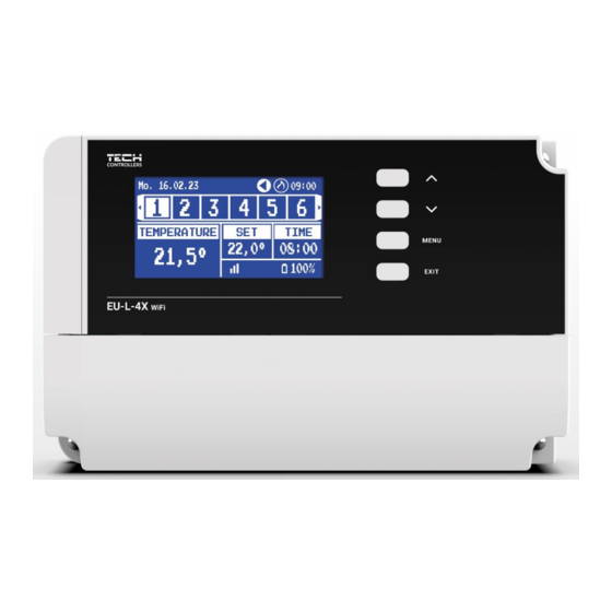
- Page 1 EU-L-4X WiFi...
-
Page 3: Table Of Contents
TABLE OF CONTENTS Safety ....................................4 System description ................................5 III. Installing the Controller ..............................5 First startup ..................................8 Main screen description ..............................9 Controller functions ............................... 11 Operation mode ................................11 Zones .................................... 12 Controller settings ................................ 13 Fitter’s Menu ................................ -
Page 4: Safety
I. SAFETY Before operating the device, please read the following instructions carefully. Failure to observe the instructions may cause personal injuries and damage the device. Please store this manual for future reference. To avoid unnecessary errors and accidents, make sure that all persons operating the device have thoroughly familiarized themselves with the device operation and its safety functions. -
Page 5: System Description
II. SYSTEM DESCRIPTION The EU-L-4X WiFi board is designed to control the heating device and supports 4 zones. It also supports wireless and wired RS-485 (TECH SBUS) communication. Due to the additional EU-ML-4X module, WiFi allows expansion of the installation by an additional 4 zones. - Page 6 An illustrative diagram explaining how to connect and communicate with the remaining equipment:...
- Page 7 Installation of the electrolytic capacitor In order to reduce the phenomenon of temperature spikes being read from the zone sensor, a 220uF/25V low impedance electrolytic capacitor, connected in parallel with the sensor cable, should be installed. When installing the capacitor, always pay particular attention to its polarity.
-
Page 8: First Startup
In order for the controller to operate correctly, the following steps must be followed for the first start-up: Step 1: Connecting the EU-L-4X WiFi assembly board with all the devices it is supposed to control To connect the wires, remove the controller cover and then connect the wiring – this should be done as described on the connectors and the diagrams in the manual. -
Page 9: Main Screen Description
Step 4. Configuring temperature sensors, room regulators In order for the EU-L-4X WiFi board to support a given zone, it must receive information about the current temperature. The simplest way is to use a wired or wireless temperature sensor (e.g. EU-C-7p, EU-C-mini, EU-CL-mini, EU-C-8r). However, if the operator wishes to be able to change the set temperature value directly from the zone, the operator can use general room regulators, e.g. - Page 10 Sample screens - ZONES 1. Current day of the week 2. Outside temperature 3. Pump ON 4. Activated potential-free contact zone heating ON zone cooling ON 5. Current time 6. Active bypass function in the zone – see section VI. 4.14. Heat pump 7.
-
Page 11: Controller Functions
Sample Screen - ZONE 1. Outside temperature 8. Maximum floor temperature 2. Battery status 9. Information on the number of registered 3. Current time window sensors in the zone 4. Current mode of operation of the displayed 10. Information about the number of registered zone actuators in the zone 5. -
Page 12: Zones
ZONES ➢ ON To display the zone as active on the screen, register a sensor in it (see: Fitter’s Menu). The function allows you to disable the zone and hide the parameters from the main screen. ➢ Set temperature The set temperature in the zone results from the settings of a specific mode of operation in the zone, i.e. the weekly schedule. However, it is possible to by-pass the schedule and set up a separate temperature and temperature duration. -
Page 13: Controller Settings
To configure a schedule: • Use the arrows to select the part of the week for which the set schedule will apply (1st part of the week or 2nd part of week). • Use the MENU button to go to the set temperature settings that will apply outside the time intervals - set it with the arrows, confirm using the MENU button •... - Page 14 ➢ Calibration - Room sensor calibration is carried out during assembly or after a longer period of use of the sensor if the displayed room temperature deviates from the actual one. Adjustment range: from -10°C to +10°C, with a step of 0.1°C.
- Page 15 Room temperature - Room temperature - OPTIMUM START function OFF: OPTIMUM START function active: – programmed moment of changing the economic temperature to the comfortable one Activating this function will ensure that when the programmed change of the set temperature resulting from the schedule occurs, the current temperature in the room will be close to the desired value.
- Page 16 Example: Zone preset temperature: 23˚C Minimum opening: 30% Maximum opening: 90% Range: 5˚C Hysteresis: 2˚C With the above settings, the actuator will start to close once the temperature in the zone reaches 18°C (preset temperature minus the range value). The minimum opening will occur when the zone temperature reaches the set point. Once the set point is reached, the temperature in the zone will start to drop.
- Page 17 4.1.8. FLOOR HEATING ➢ Floor Sensor • Sensor Selection - This function is used to enable (wired) or register (wireless) floor sensor. In the case of a wireless sensor, register occurs by additionally pressing the communication button on the sensor. •...
-
Page 18: Additional Contacts
MIXING VALVE The EU-L-4X WiFi board can operate an additional valve using a valve module (e.g. the EU-i-1m). This valve has RS communication, but it is necessary to carry out the registration process, which will require users to quote the module number located in the rear of its housing, or in the software information screen). - Page 19 ➢ Calibration - This function can be used to calibrate the built-in valve, e.g. after prolonged use. During calibration, the valve is set to a safe position, i.e. for the CH valve and Return protection types to fully open position, and for floor valve and Cooling types - to closed position.
- Page 20 CAUTION If the Boiler Protection is off, the CH temperature will not affect the opening of the valve. In extreme cases, the boiler may overheat, so it is recommended to configure the boiler protection settings. For this type of valve, refer to the Return Protection Screen.
- Page 21 • Change of the pre-set temperature- This setting determines how many degrees the valve temperature will increase or decrease with a unit change in room temperature (see: Room temperature difference). This function is only active with the RS room regulator and is closely related to the Room temperature difference parameter.
- Page 22 CAUTION The function does not appear for the valve type Cooling. ➢ Valve pump • Pump operation modes – the function allows users to select the pump operation mode: → Always ON - pump runs at all times regardless of temperature →...
- Page 23 Example: Temperature - Set Time Weekly Control Monday ‐ 7 +5°C PRESET ‐ 14 ‐10°C ‐ 22 +7°C In this case, if the temperature set on the valve is 50°C, on Mondays, from 4 to 7 hours, the temperature set on the valve will increase by 5°C, or to 55°C, while in the hours from 7 to 14 , it will decrease by 10°C, so it will be 40°C, and...
-
Page 24: Internet Module
EXTERNAL SENSOR CAUTION This function is only available when a EU-C-8zr external sensor has been registered in the EU-L-4X WiFi board. Registering the external sensor allows users to switch on the weather control. ➢ Sensor selection – to select a wireless EU-C-8zr sensor that requires registration. -
Page 25: Potential-Free Contact
PUMP The EU-L-4X WiFi controller controls the operation of the pump – it switches on the pump (after counting down the delay time) when any of the zones is underheated and when the floor pump option is enabled in the respective zone. When all zones are heated (the set temperature is reached), the controller switches off the pump. -
Page 26: Language
4.13. LANGUAGE The function allows users to change the controller language version. 4.14. HEAT PUMP This is a mode dedicated for an installation operating with a heat pump and enables optimal use of its capabilities. ➢ Energy saving mode – selecting this option will start the mode and more options will appear ➢... - Page 27 STT-868 actuator alarms ERROR #0 Flat battery in the actuator Replace the batteries ERROR #1 Some mechanical or electronic Contact the service staff parts have been damaged ERROR #2 - No piston controlling the valve - Too big stroke (movement) of the - Install a piston controlling the actuator valve - Check the valve stroke...
-
Page 28: Software Upgrade
- Current sensor is damaged ERROR #8 - Limit switch sensor error Limit switch sensor damaged EU-G-X actuator alarms Locked/damaged actuator piston. Check Bolt retraction to mounting position ERROR #1 - Calibration error 1 the assembly and recalibrate the took too long. actuator. -
Page 29: Technical Data
VIII. TECHNICAL DATA Power supply 230V ± 10% / 50 Hz Max. power consumption Ambient temperature 5 ÷ 50°C Maximum load of potential outputs 1-8 0.3A Maximum load of pump 0.5A 230V AC / 0.5A (AC1) * Potential-free cont. nom. out. load 24V DC / 0.5A (DC1) ** Thermal resistance of NTC sensor -30 ÷... - Page 30 EU DECLARATION OF CONFORMITY Hereby, we declare under our sole responsibility that EU-L-4X WiFi manufactured by TECH STEROWNIKI II Sp. z o.o., head‐ quartered in Wieprz Biała Droga 31, 34‐122 Wieprz, is compliant with Directive 2014/53/EU of the European parliament and...
Need help?
Do you have a question about the EU-L-4X WiFi and is the answer not in the manual?
Questions and answers