
Related Manuals for Sune Technology PCM3.1


Summary of Contents for Sune Technology PCM3.1
- Page 1 Installation Manual Multimedia Interface for Porsche PCM3.1 SUNE TECHNOLOGY CO.,LTD No.9,Lane 606,Anping Rd,Tainan City 70849,TAIWAN TEL:+88662292246 FAX: +88662288104 Http://www.sune-tech.com SKYPE:sune_tech or hsin_han99 http://www.carnavi-tech.com Shop...
- Page 2 Compatibility: Porsche PCM3.1 system Components: Interface Main*1 Sub Board*1 Interface Input / Output specification : Input: LVDS*1 CVBS(Front Camera)*1 CVBS(Rear Camera)*1 Output: Power Spec: Input Power: 8VDC ~ 18VDC Consumption: 5WATT Switch input mode: External video sources skip function: Able to control input videos on and off...
-
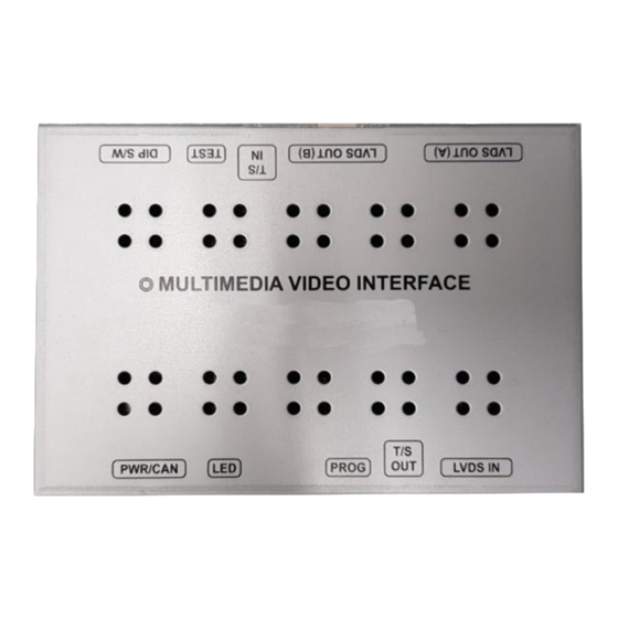
Page 3: Main Board
MAIN BOARD POWER CABLE POWER / CAN LVDS CABLE QCPASS1411 HPOWER0259 J by J CABLE HLVDSC0069 HPOWER0045 FFC Cable*2ea SUB BOARD Touch cable*1ea Bracket FFCABL 0008 QCPASS1403 HTOUCH0027 FFC Cable*1ea FFC Cable*1ea BUTTON CABLE 4Pin Touch CABLE FFCABL0056 FFCABL0057 HARETC0001 HTOUCH0022 IR CABLE REMOTE CTRL. - Page 4 ON: DOWN / OFF: UP * Please make sure to disconnect the power cable of interface and reconnect to apply dip switch setting whenever changing DIP switch. 8POL DIP SWITCH SETTING DIP S/W STATUS DESCRIPTION LVDS Navigation Mode DIP1 LVDS Navigation Mode Skip Ext.
- Page 5 FUNCTION POWER & PIP MENU Activating OSD menu Making a selection, changing image display ▲ Moving upward ▼ Moving downward Moving leftward ◀ (If you press this button 2 seconds long, you can access the factory mode) Moving rightward ▶ (If you press this button 2 seconds long, you can reset all the data about user environment)
- Page 6 Menu of FACTORY IMAGE IMAGE H-POSITION PARK V-POSITION H-POSITION/V-POSITION Setting UTIL1 UTIL2 INFO MENU to Return SEL to Select/Save Menu of FACTORY IMAGE PAS TYPE PARK PAS SETUP UTIL1 REAR TYPE UTIL2 RADAR ENABLE INFO AUTO FCAM TIME MENU to Return SEL to Select/Save PARK PAS TYPE: Select parking line type.
- Page 7 Menu of FACTORY UTIL1 IMAGE LVDS MODEL PARK CAR MODEL LVDS MODEL: Android, car-play, navigation model UTIL1 UTIL2 setting INFO CAR MODEL: MENU to Return SEL to Select/Save UTIL2 Menu of FACTORY IMAGE HANDLE BUTTON HANDLE BUTTON: Select the usage of handle button PARK FACTORY RESET UTIL1...
- Page 8 Monitor *Press and hold Navi button for mode change *On rear Camera mode, please press Navi button to show small PDC screen on the screen. Steering Wheel *Press and hold back button for 5seconds to do mode change...
- Page 9 4Pin touch cable LVDS Cable No Use No Use Touch generated by Uart HPOWER0259 in HDMI connector CARPLAY Android Navi HPOWER0045...
- Page 10 AUX L & R CAM-12V R-DET Remote control F-DET FCAM IN Toggle button RCAM IN...
- Page 11 ① ① Disassemble the monitor and connect the touch cable from the back of LCD as shown on the left - OEM Gold touch cable → Supplied touch cable (HTOUCH0027) - Supplied FFC cable → Supplied touch cable (FFCABL0033) (HTOUCH0027) - Supplied black FFC cable →...
- Page 12 ③ ③ This picture is another side of LCD Loosen 3 bolts which are marked on the left. ④ ④ Connect supplied FFC cable to marked place ① - Supplied 50P FFC cable → (FFCABL0057) ① ② - Supplied 30P FFC cable → (FFCABL0056) ②...
- Page 13 ⑤ ⑤ place the bracket where bolts were loosen and tighten bolts again ⑥ ⑥ On the top of bracket, place the subboard and connect the supplied FFC cables as shown on the left...
- Page 14 ⑦ ⑦ Pull the cables on the backside of LCD through the marked place. ⑧ ⑧ Connect cables as shown on the left - Black FFC cable → LCD OUT - FFC cable → LCD IN ① - Original 50P FFC cable → ①...
- Page 15 ⑨ ⑨ After all FFC cables installed, the looking is as left picture. ⑩ ⑩ Please connect 4Pin touch cable on the sub board and then please connect it to Main Interface. After that, please connect LVDS cable between sub board and Main Interface.
- Page 16 Q. I cannot change mode A. Check connection of Ground cable and IR Cable. Check LED lamp is on, if not check connection of POWER cable. Q. All I got on the screen is black. A. Check second LED lamp of the interface is on, if not, check A/V sources connected are working well.
Need help?
Do you have a question about the PCM3.1 and is the answer not in the manual?
Questions and answers