Advertisement
Table of Contents
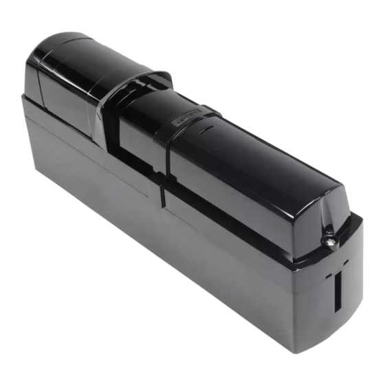
OVS-50TNR Quick Setup Guide
Mounting and Wiring (you must remove sensor from backplate for mounting)
1. Remove front covers, then cable connectors of transmitter and receiver.
Remove the bottom cover:
1
Loosen the cover
lock screw
2. Remove the main optical unit from the transmitter and receiver.
Transmitter and receiver:
Remove the main optical unit from the back housing
1
Loosen the optical unit mounting screw.
Note: Optical unit shown at 90°
3. Mount and wire the units
Mounting holes
(receiver and transmitter):
Using a screwdriver or similar tool, break the
1
knockout position in the back housing.
Knockout position
Mounting
hole
(knockout)
Mounting
hole
2
Remove the main unit cover:
Pull
Loosen the main unit
cover lock screw
2
Take the main optical unit out
continued on the back
18730 S. Wilmington Ave, Unit 100
Rancho Dominguez, CA 90220
Ph 800 877-6656
Fax 310 898-1098
www.optex-vs.com
Pull and
slide up
of the back housing
(receiver only):
Again using a screw-
2
driver or similar tool,
break the knockout
position in the back
housing.
OPTEX Inc.
(East Coast Office)
8510 McAlpine Park Dr.
Suite 108
Charlotte, NC 28211
Unplug the wired
3
connectors:
Interface
board
Knockout
(knockout)
Use bottom knockouts for
external wiring
Advertisement
Table of Contents

Related Manuals for Optex OVS-50TNR


Summary of Contents for Optex OVS-50TNR
- Page 1 OVS-50TNR Quick Setup Guide Mounting and Wiring (you must remove sensor from backplate for mounting) 1. Remove front covers, then cable connectors of transmitter and receiver. Remove the bottom cover: Remove the main unit cover: Unplug the wired connectors: Loosen the cover...
- Page 2 3. Mount and wire the units (continued from front) Using the template, mount the back Open the plate and then housing to the wall or post. route the Gate Operator wires from the rear of the back housing through the Gate knockout holes.
Need help?
Do you have a question about the OVS-50TNR and is the answer not in the manual?
Questions and answers