Table of Contents
Advertisement
Quick Links
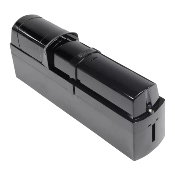
BATTERY OPERATED
PHOTOELECTRIC DETECTOR
OVS-50TNR
FEATURES
• Easy installation with battery driven transmitter
• 8 years battery life with 2pcs. of SAFT LSH-20
• Simplified optical adjustment -Sniper View Finder with ×2 magnification
1
INTRODUCTION
1-1 BEFORE YOUR OPERATION
・The system must install in ordinary locations in accordance with the in Canada general requirements are given in CSA Standard C22.2 No.0, General Requirements
– Canadian Electrical Code, Part II.
• Read this instruction manual carefully prior to installation.
• After reading, store this manual carefully in an easily accessible place for reference.
• This manual uses the following warning indications for correct use of the product, harm to you or other people and damage to your assets, which are described below.
Be sure to understand the description before reading the rest of this manual.
Indicates a potentially hazardous situation which, if not avoided,
will result in minor or moderate injury, or may result in serious
Warning
injury or death.
Additionally there may be significant property damage.
Indicates a potentially hazardous situation which, if not avoided,
Caution
may result in minor or moderate injury or in property damage.
This symbol indicates prohibition. The specific prohibited action is provided in
and/or around the figure.
This symbol requires an action or gives an instruction.
This symbol indicates recommendation.
Do not use this product for any other purpose other than its intended use on automatic gates.
This product is not intended for use on Industrial Doors or Vertical gates and does not comply
with UL 325 for those applications.
Do not touch the unit base or power terminals of the product with a wet
hand (do not touch when the product is wet with rain, etc.). It may cause
electric shock.
Never attempt to disassemble or repair the product. It may cause fire or
damage to the devices.
Do not use batteries that have different levels of power remaining (i.e., new and
used batteries). Not observing the above may result in an explosion, leakage of
electrolyte, emission of toxic gases or other outcomes that may be harmful to
people and property.
[Handling of Batteries] Do not recharge, short circuit, crush, disassemble, exceed heat
above 100°C (212°F), incinerate, or expose contents to water. Do not solder directly to
the cell.
Do not pour water over the product with a bucket, hose, etc. The water may
enter, which may cause damage to the devices.
Clean and check the product periodically for safe use. If any problem is found, do not
attempt to use the product as it is and have the product repaired by a professional
engineer or electrician.
1-2 PRECAUTIONS
Install the unit at 13" height from the
ground level.
13" ± 2"
(330 ± 50 mm)
※ No less than 11"
Warning
Caution
Do not install the unit on an unstable
Do not install the pole in a location
surface.
where sufficient stability can not be
ensured.
• Slim body design
• Easy to see LED optical alignment
• IP65 waterproof structure
• Outdoor use / Usage extérieur
Le non respect des instructions indiquées par signe et un
Avertissement
mauvais maniement peuvent causer la mort ou des blessures
graves.
Le non respect des instructions indiquées par ce signe et un
Attention
mauvais maniement peuvent causer des blessures et/ou des
dommages matériels.
Ce symbole signifie interdiction. L'action interdite est décrite dans et/ou autour de l'image.
Ce symbole demande une action ou donne une instruction.
N'utilisez pas ce produit à d'autres fins que son utilisation prévue sur les
portails automatiques. Ce produit n'est pas destiné à être utilisé sur des
portes industrielles ou des portails verticaux et n'est pas conforme à la
norme UL 325 pour ces applications.
Ne pas toucher l'unité ou les bornes électriques du produit avec une main
humide (ne pas toucher si le produit a été mouillé par la pluie, etc.).
Il y a un risque de choc électrique.
Ne jamais essayer de démonter ou de réparer le produit. Cela pourrait
causer un incendie ou endommager le dispositif.
Ne pas utiliser des batteries avec des niveaux de charges différents
(par ex., des batteries neuves avec des usagées). Le non respect de ce
qui précède peut causer une explosion, une fuite d'électrolyte, une émission
de gaz toxiques ou une conséquence nocive aux personnes et aux biens.
[Manipulation des batteries] Ne pas recharger, court-circuiter, écraser,
démanteler, porter à une température supérieure à 100°C (212°F), incinérer,
ou exposer le contenu à de l'eau. Ne pas souder directement à la cellule.
Ne pas verser d'eau sur le produit avec un seau, un tuyau, etc. De l'eau
pourrait pénétrer et endommager l'appareil.
Nettoyer et vérifier périodiquement le produit pour une utilisation en toute
sécurité. Si vous rencontrez un problème, n'essayez pas d'utiliser le produit
en l'état, faites le réparer par un ingénieur ou électricien professionnel.
Do not install the unit in trees, leaves,
or other objects that may swing in the
wind and block the beam.
- 1 -
Installation INSTRUCTIONS
MODEL
DETECTION RANGE
OVS-50TNR
50 ft. / 15 m
Avertissement
Attention
Avoid installing the receiver in a location
where rising or setting sun may go
directly into the receiver.
No. 59-2882-1
Advertisement
Table of Contents

Related Manuals for Optex OVS-50TNR


Summary of Contents for Optex OVS-50TNR
- Page 1 No. 59-2882-1 INSTALLATION INSTRUCTIONS MODEL DETECTION RANGE BATTERY OPERATED OVS-50TNR 50 ft. / 15 m PHOTOELECTRIC DETECTOR OVS-50TNR FEATURES • Easy installation with battery driven transmitter • Slim body design • 8 years battery life with 2pcs. of SAFT LSH-20 •...
- Page 2 1-3 PARTS IDENTIFICATION Main unit cover Main unit Back box Accessories>> Main unit mounting Optical unit bracket 4×25 self tapping for wall mounting (with rubber washer): 4 Optical lens Viewfinder Main unit cover Optical alignment dial lock screw Battery Plate M4×16 screws for pole mounting Dip SW (Receiver only)
- Page 3 Close the battery plate . Insert Interface board into the slots on the back box and then connect Fill the holes with the wires the wires to nterface board terminals. using the some putty. 2-3 WALL MOUNTING (Transmitter & Receiver) Using a screwdriver or similar tool, break the knockout position (×2) Mount the back box to the wall.
- Page 4 Referring to “4 SETTING” on page 5, perform the necessary settings. Close the battery cover. Close the main unit cover. Just fit Hook on the upper part Fasten the main unit Push the lower part of Tighten the fixing screw for Close the battery cover.
- Page 5 SETTINGS 3-1 FUNCTIONS DIP SWITCH Refer to “1-3 PARTS IDENTIFICATION”. BEAM INTERRUPTION ADJUSTMENT Initial setting is at 20ms. Receiver Beam interruption adjustment switch Set the beam interruption adjustment switches of the Receiver according to the required response time. Disabled If get longer, less false alaarm. SELECTOR POSITION (factory default)
- Page 6 OPERATION CHECK 4-1 LED INDICATION Alignment / Level indicator LED (Receiver only) Power / Low battery indicator LED Transmitter and Receiver DETECTOR BATTERY ON (continue) CONDITION Beam Interruption Power / Low battery Beam not ON (continue) Fast Slow Normal indicator LED received sufficiently blink blink...
- Page 7 OPTEX KOREA CO.,LTD. (Korea) www.optex-vs.com www.optex-security.com www.optexkorea.com OPTEX CO., LTD. (JAPAN) OPTEX SECURITY Sp.z o.o. (Poland) OPTEX (DONGGUAN) CO.,LTD. OPTEX (EUROPE) LTD. / EMEA HQ (U.K.) SHANGHAI OFFICE (China) URL: http://www.optex.net www.optex-europe.com www.optex.com.pl www.optexchina.com OPTEX TECHNOLOGIES B.V. OPTEX PINNACLE INDIA, PVT., LTD. (India) (The Netherlands) www.optex.net/in/en/sec...
Need help?
Do you have a question about the OVS-50TNR and is the answer not in the manual?
Questions and answers